Page 320 of 1708

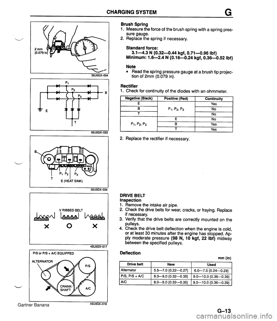
CHARGING SYSTEM G * ttt I E (HEAT SINK) 05UOGX-034 V RIBBED BELT X 0 X Brush Spring 1. Measure the force of the brush spring with a spring pres- sure gauge. 2. Replace the spring if necessary. Standard force: 3.14.3 N (0.32-444 kgf, 0.71-0.96 Ibf) Minimum: 1.6--2.4 N (0.16-0.24 kgf, 0.36-0.52 Ibf) Note Read the spring pressure gauge at a brush tip projec- tion of 2mm (0.079 in). Rectifier 1. Check for continuity of the diodes with an ohmmeter. I Negative (Black) I Positive (Red) I Continuity 1 I E I I Yes I -- 2. Replace the rectifier if necessary. DRIVE BELT Inspection 1. Remove the intake air pipe. 2. Check the drive belts for wear, cracks, or fraying. Replace if necessary. 3. Verify that the drive belts are correctly mounted on the pulleys. 4. Check the drive belt deflection when the engine is cold, or at least 30 minutes after the engine has stopped. Ap- ply moderate pressure (98 N, 10 kgf, 22 Ibf) midway between the specified pulleys. Deflection mm {in) I Drive belt New Used Alternator PIS, PIS + A/C 5.b7.0 {0.224.27) 8.0-9.0 iO.32-0.35) 6.W7.5 (0.24--0.29) 9.0-1 0.0 {0.36-0.391 Gartner Banana
Page 321 of 1708

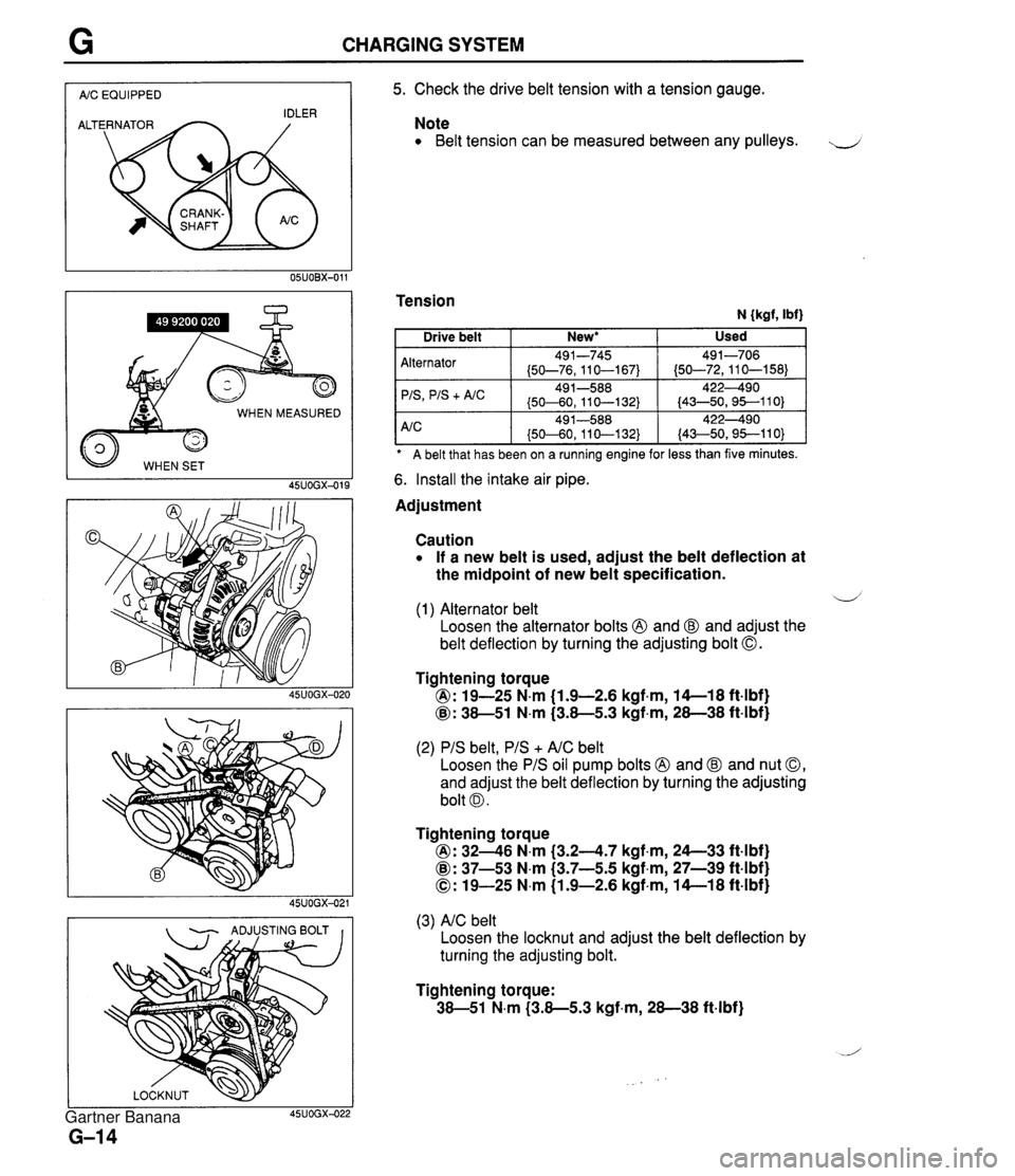
CHARGING SYSTEM I AIC EQUIPPED I WHEN MEASURED 45UOGX-015 - ADJUSTING BOLT I I 5. Check the drive belt tension with a tension gauge. Note Belt tension can be measured between any pulleys. J Tension N {kgf, Ibf) A belt that has been on a ruining engine for less than five minutes. Alternator 'IS
+ A/C 6. Install the intake air pipe. Used Drive belt Adjustment New* I Caution If a new belt is used, adjust the belt deflection at the midpoint of new belt specification. 491-745 (50-76,110-167) 49 1-588 (50-60, 11 0-1 32) d (1) Alternator belt Loosen the alternator bolts @ and @ and adjust the belt deflection by turning the adjusting bolt 0. 491-706 (50-72,110-158) 422490 (43-50,95--110) Tightening torque @: 19-25 N.m (1.9-2.6 kgf.m, 14-1 8 ft4bf) @: 38-51 N.m (3.8-5.3 kgf,m, 28-38 ft-lbf) (2) PIS belt, PIS + AIC belt Loosen the PIS oil pump bolts @ and @ and nut 0, and adjust the belt deflection by turning the adjusting bolt 0. Tightening torque @: 3246 N.m (3.24.7 kgf.m, 24--33 ft4bf) @: 37-53 N.m (3.7-5.5 kgf,m, 27-39 ft-lbf) 0: 19-25 N.m (1.9-2.6 kgf-m, 14-1 8 ft-lbf) (3) AIC belt Loosen the locknut and adjust the belt deflection by turning the adjusting bolt. Tightening torque: 38-51 N.m (3.8-5.3 kgf-m, 28-38 ft-lbf) Gartner Banana
Page 705 of 1708
P ANTILOCK BRAKE SYSTEM (ABS) Troubleshooting procedure 2. ALTEnuAtOR TEST START mtmE (ALTWJATOR TESTED BY RWNa ENQlNE) 3. A88 SYSTEM TEST TURN IGNITION K€Y ON (00 NOT ROES EWWE) - - 1. LOCATE ABS CONTROL UNIT. 2. DISCONNECT CONTROL UNlT HARNESS CONNECTOR FROM CONTROL UNIT. 3. CONNECT ABS TESTER HARNESS TO CONTROL UNlT HARNESS CON- NECTOR. 4. TURN IGNITION KEY TO ON POSITION. TESTER WlLL RAPIDLY DISPLAY SEVERAL MESSAGES DURING AN INITIAL SEGMENT CHECK I THEN 1 I MAZDA ABS 2 TEST 1 4 I YES ENG RUN? NO 1 I MAZDA ALT TEST I CHK ALTERNATOR NO FAULT DETECTED t I TURN OFF ENGINE I TESTER WlLL RAPIDLY DISPLAY SEVERAL MESSAGES DURING AN INITIAL SEGMENT CHECK. I THEN t 1 YES ENG RUN? NO t 1 MAZDA ABS 2 TEST I Gartner Banana
Page 716 of 1708

ANTILOCK BRAKE SYSTEM (ABS) P ABS CONTROL UNIT 35-PIN CONNECTOR OHMMETER 15UOPX-OI Check rotor Check the rotor for missing or damaged teeth and replace as necessary. Check alternator Refer to section G. Check wheel-speed sensor Caution To prevent damage to the terminals, create a probe by wrapping a thin wire around the tester lead before inserting. 1. Using an ohmmeter, check for continuity at the control unit connector terminals. 0----0: Indicates continuity Right front Left rear Right rear 2. If the continuity is not as specified, check the wiring har- ness (Wheel-speed sensor - Control unit). 3. If the continuity is OK, check voltage between 1K and 1 G, 10 and 1 Q, 1 U and 1 F, and 1 L and 1 P while rotating the wheel one rotation per second by hand. 4. If voltage is not approximately 50 mV--60 mV, the wheel-speed sensor is faulty. 5. If voltage is approximately 50 mV-60 mV, the control unit is faulty. 1L Check hydraulics Verify that all brake fluid connections are tight and that no fluid is leaking. IP 1Q Left front 0--0 Check hydraulic unit wiring 1. Verify that the hydraulic unit connectors are properly secured. 2. Verify that the valve relay and motor relay are properly secured. IG 1K 0-4 1U 10 S-0 IF 0-4 Gartner Banana
Page 856 of 1708

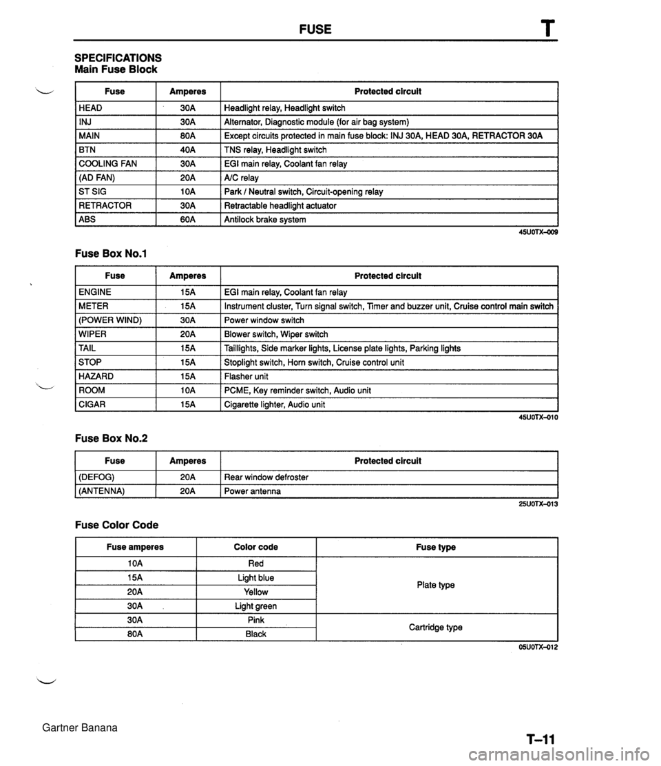
FUSE SPECIFICATIONS Main Fuse Block u I Fuse Amperes Protected circuit HEAD INJ MAIN BTN 30A 30A COOLING FAN (AD FAN) 1 ABS I 60A I Antilock brake svstem I Headlight relay, Headlight switch Alternator, Diagnostic module (for air bag system) 80A 40A ST SIG RETRACTOR Fuse Box No.1 Except circuits protected in main fuse block: INJ 30A, HEAD 30A, RETRACTOR 30A TNS relay, Headlight switch 30A 20A EGI main relay, Coolant fan relay A/C relay 10A 30A Park l Neutral switch, Circuit-opening relay Retractable headlight actuator Fuse ENGINE METER (POWER WIND) Amperes 15A WIPER TAIL ROOM I 10A I PCME, Key reminder switch, Audio unit I Protected circuit EGI main relay, Coolant fan relay 15A 30A STOP HAZARD CIGAR 15A I Cigarette lighter, Audio unit 1 Instrument cluster, Turn signal switch, Timer and buzzer unit, Cruise control main switch Power window switch 20A 15A Fuse Box No.2 Blower switch, Wiper switch Taillights, Side marker lights, License plate lights, Parking lights 15A 15A Fuse Amperes Protected circuit I Stoplight switch, Horn switch, Cruise control unit Flasher unit Fuse Color Code (DEFOG) (ANTENNA) I Fuse amperes I Color code Fuse type 25UOTX-013 20A 20A I I 10A Red 1 I Rear window defroster Power antenna Plate type 15A 20A Light blue Yellow 30A 30A 80A Light green Pink Black Cartridge type Gartner Banana
Page 879 of 1708
T WARNING LIGHT AND SENDER UNIT WARNING LIGHT AND SENDER UNlT STRUCTURAL VIEW 1. Brake system warning light 2. Seat belt warning light 3. Air bag system warning light 4. Retractor indicator light 5. Alternator warning light 6. MIL (malfunction indicator light) 7. O/D OFF indicator light 8. Antilock brake system warning light 9. Washer level indicator light 10. Rear window defroster indicator light Reference Table Warning indicator light SRS air bag system Retractor indicator light Alternator MIL (malfunction indicator light) O/D OFF Antilock brake system Washer level 45UOTX-062 T-34 Reference page or section T-154 T- 48 section G section F section K section P T- 39 J Gartner Banana
Page 1405 of 1708
1830 ALTERNATOR ? I 1830 -1 ALTERNATOR I PAHI' SO. 101'yI COVER ,REAR-ALTERHATO R (6) ALTERNATOR (HTI (AT) STATOR RECTIFIER BE,lRIt4GD BALL-ALT . FW Ot* T BRUSH SCREW SET PULLEY NUT SET -. --.--. ...-- CAT . AUNAU6- 05 Gartner Banana
Page 1406 of 1708
I 2030 -2 * ALTERNATOR - SCREW SET TERMINAL SET Gartner Banana