Page 73 of 1708
DISASSEMBLY AUXILIARY PARTS 1. Drain the engine oil. 2. Disassemble in the order shown in the figure. 1. Ignition coil and high-tension lead 2. Crankshaft position sensor 3. Manifold bracket 4. Intake manifold assembly 5. Alternator 6. Alternator bracket 7. Right engine mount 8. Oil filter 9. Oil cooler 10. Oil pressure switch 11. Water outlet pipe 12. Spark plug 13. Dipstick and pipe 14. Engine hanger Gartner Banana
Page 116 of 1708

ASSEMBLY B Oil Filter 1. Remove all foreign material from the oil filter mounting surface. 2. Apply a small amount of clean engine oil to the rubber seal of the oil filter. 3. Install the oil filter and tighten it by hand until the rubber seal contacts the base. 4. Hand tightening type (Numbers printed on filter) Tighten the filter 314 of a turn by hand after it contacts the cylinder block. If tightening by hand is difficult, use the filter wrench. Example When the oil filter contacts the cylinder block at "l", turn it 314 of a turn further to "4". Filter wrench tightening type (No numbers printed on fil- ter) Tighten the filter 1 and 116 turns with the filter wrench af- ter it contacts the cylinder block. Right Engine Mount Install the right engine mount. Tightening torque: 37-53 N-m (3.7-5.5 kgf.m, 27-39 ft.lbf) Alternator Bracket Install the alternator bracket. Tightening torque: 64-49 N-m (6.5--9.1 kgf-m, 48-45 ft4bf) Alternator Install the alternator and hand tighten the mounting bolts. Gartner Banana
Page 123 of 1708

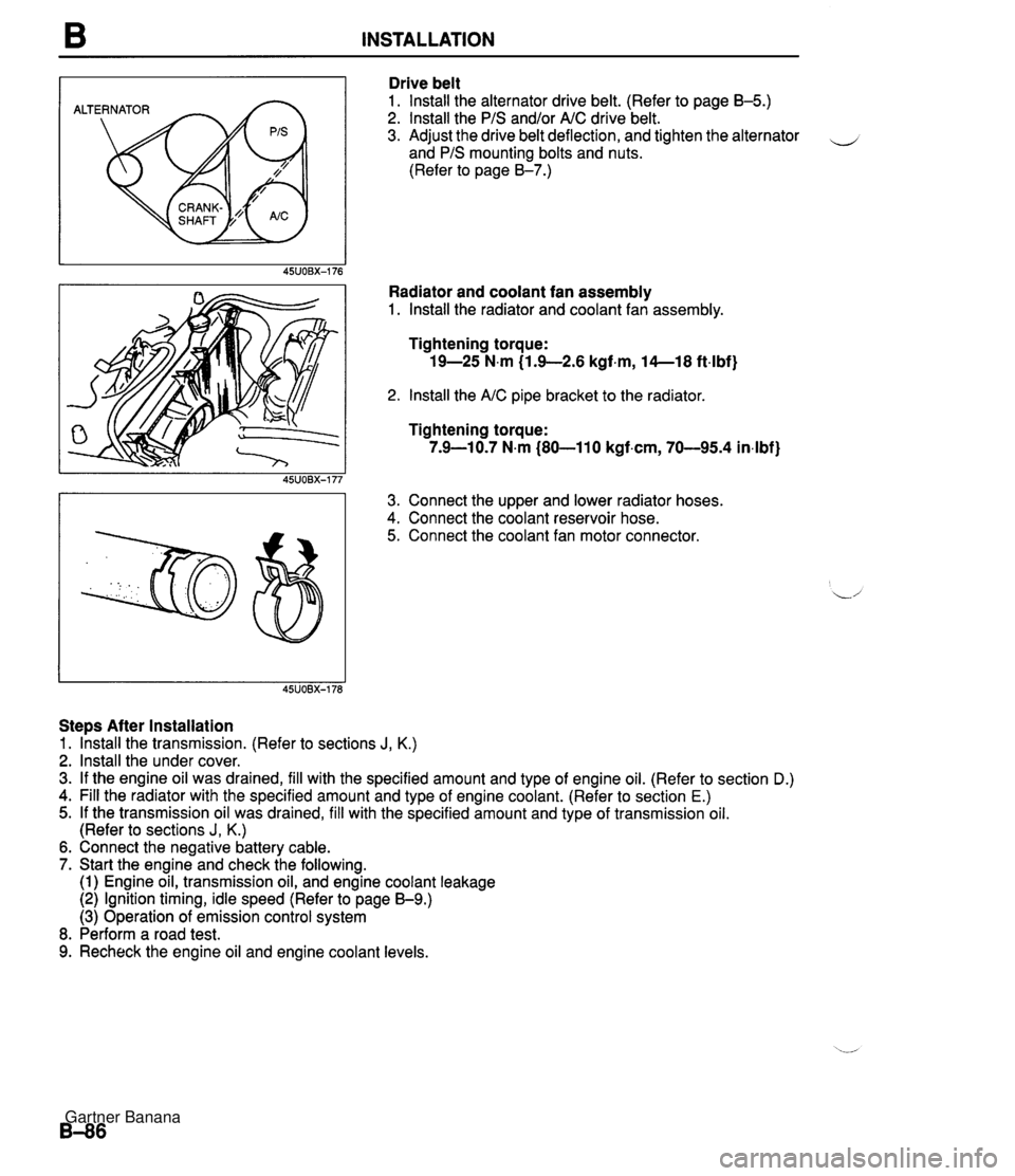
B INSTALLATION ALTERNATOR Drive belt 1. lnstall the alternator drive belt. (Refer to page B-5.) 2. lnstall the PIS and/or AIC drive belt. 3. Adjust the drive belt deflection, and tighten the alternator - and PIS mounting bolts and nuts. (Refer to page 8-7.) Radiator and coolant fan assembly 1. lnstall the radiator and coolant fan assembly. Tightening torque: 19-25 N.m (1.9-2.6 kgf.m, 14--18 ft4bf) 2. lnstall the AIC pipe bracket to the radiator Tightening torque: 7.9-10.7 N.m (80-110 kgf.cm, 70-95.4 in4bf) 3. Connect the upper and lower radiator hoses. 4. Connect the coolant reservoir hose. 5. Connect the coolant fan motor connector. Steps After Installation 1. lhstall the transmission. (Refer to sections J, K.) 2. lnstall the under cover. 3. If the engine oil was drained, fill with the specified amount and type of engine oil. (Refer to section D.) 4. Fill the radiator with the specified amount and type of engine coolant. (Refer to section E.) 5. If the transmission oil was drained, fill with the specified amount and type of transmission oil. (Refer to sections J, K.) 6. Connect the negative battery cable. 7. Start the engine and check the following. (1) Engine oil, transmission oil, and engine coolant leakage (2) Ignition timing, idle speed (Refer to page 59.) (3) Operation of emission control system 8. Perform a road test. 9. Recheck the engine oil and engine coolant levels. Gartner Banana
Page 308 of 1708

Before beginning any service procedure. refer to section T of this manual for air bag system service warnings and audio antitheft system alarm conditions . ENGINE ELECTRICAL SYSTEM INDEX ....................................... G- 2 OUTLINE ..................................... G- 3 SPECIFICATIONS ........................... G- 3 TROUBLESHOOTING GUIDE .................. G- 4 CHARGING SYSTEM .......................... G- 6 PREPARATION ............................. G- 6 CIRCUIT DIAGRAM ......................... G- 6 TROUBLESHOOTING ....................... G- 7 BATTERY .................................. G- 8 ALTERNATOR .............................. G-10 DRIVE BELT ................................ G-13 IGNITION SYSTEM ............................ G-15 PREPARATION ............................. G-15 CIRCUIT DIAGRAM ......................... G-15 TROUBLESHOOTING ....................... G-16 IGNITION TIMING ........................... G-17 SPARK PLUG ............................... G-18 IGNITION COIL ............................. G-19 IGNITER ................................... G-19 HIGH-TENSION LEAD ....................... G-20 STARTING SYSTEM ........................... G-21 CIRCUIT DIAGRAM ......................... G-21 TROUBLESHOOTING ....................... G-21 STARTER .................................. G-22 STARTER INTERLOCK SWITCH (MT) ......... G-28 45UOGX401 Gartner Banana
Page 309 of 1708

G INDEX INDEX 1. Battery lnspection . . . . . . . . . . . . . . . . . page G- 8 Recharging . . . . . . . . . . . . . . . . page G- 9 Replacement . . . . . . . . . . . . . . page G-10 2. Alternator Removal / lnstallation . . . . . . . page G-10 Disassembly / Assembly . . . . page G-11 lnspection . . . . . . . . . . . . . . . . . page G-12 3. Drive belt lnspection . . . . . . . . . . . . . . . . . page G-13 Adjustment . . . . . . . . . . . . . . . . page G-14 4. Spark plug Removal / Installation . . . . . . . page G-18 Spark test . . . . . . . . . . . . . . . . . page G-18 lnspection . . . . . . . . . . . . . . . . . page G-18 5. Ignition coil lnspection . . . . . . . . . . . . . . . . . page G-19 Replacement . . . . . . . . . . . . . . page G-19 6. Igniter (in ignition coil) lnspection . . . . . . . . . . . . . . . . . page G-19 7. High-tension lead Removal / lnstallation . . . . . . . page G-20 lnspection . . . . . . . . . . . . . . . . . page G-20 8. Starter Removal / lnstallation . . . . . . . page G-22 Performance lnspection . . . . . page G-23 Disassembly / Assembly . . . . page G24 -' lnspection . . . . . . . . . . . . . . . . . page G26 9. Starter interlock switch (MT) lnspection . . . . . . . . . . . . . . . . . page G-28 Gartner Banana
Page 310 of 1708

OUTLINE OUTLINE SPECIFICATIONS (i.e. powertrain control module (engine), audio, etc.) *2 With System Selector (49 B019 9AO) test switch at SELF TEST. - Engine Item Starter Ignition system Cylinder Arrangement Battery BP DOHC MT I AT 12, Negative ground S46A24L(S) (32 Ah) Maintenance-free 20.0 A.C. I REAR Voltage V Type and capacity (5-hour rate) 12-65 -. 1 2-70 Drive belt deflection mm {in} Dark current" m A Transistorized (built-in voltage regulator) 14.3-1 4.9 21.5 I0.846) 8 (0.31 1 Ignition timing** BTDC ("CA)lrpm U Alternator 'I Dark current is the constant flow of current while the ignition switch is OFF. 45UoGX-003 New Used 101850 Ignition coil Spark plug FRONT 55-7.0 (0.22-0.27) 6.0-7.5 (0.2H.29) 101800 TY pe Primary coil winding n Secondary coil winding kR Type Plug gap mm {in) Firing order Type Output V-A Regulator type Regulated voltage V TY pe Output V-kW Molded (with igniter) - 8.7-1 2.9 (20°C (68°F)) NGK : BKR5E-11 BKR6E-11 (Standard ... MT) NIPPONDENSO : K16PR-U11 K20PR-U11 (Standard ... MT, AT) 1 .O-1.1 IO.040-0.043) 1-3-4--2 Brush length mm {in) Direct 124.95 17.0 i0.67) 11.5 I0.45) Brush length mm {in} Standard Minimum Coaxial reduction 12-1.4 17.5 i0.69) 12.0 i0.47) Standard Minimum Electronic spark advance (ESA) Powertrain control module (engine) controls spark advance Type Spark advance control Gartner Banana
Page 314 of 1708
CHARGING SYSTEM G TROUBLESHOOTING Check 1 Check if battery p Check battery (Refer to page G-8) J Check 2 I. Turn ignition switch ON Check wire harness 2. Check if voltage exists at each terminal of alternator Check 3 YES 1. Start engine Check alternator (Refer to page G-10) 2. Check if alternator warning light goes off I YES Check if drive belt t Adjust or replace drive belt (Refer to page G-14) 1 YES I Check for dark current (Refer to page G-3) I Check 1 BATTERY r"; Check 3 I ALTERNATOR WARNING LIGHT Check 2 B+: Battery positive voltage I I I B 1 Approx. 12V 1 Approx. 12V I B+ ON ON (Idle) L S 45UOGX-006 OV Approx. 12V Approx. 1V Approx. 12V B+ B+ Gartner Banana
Page 317 of 1708

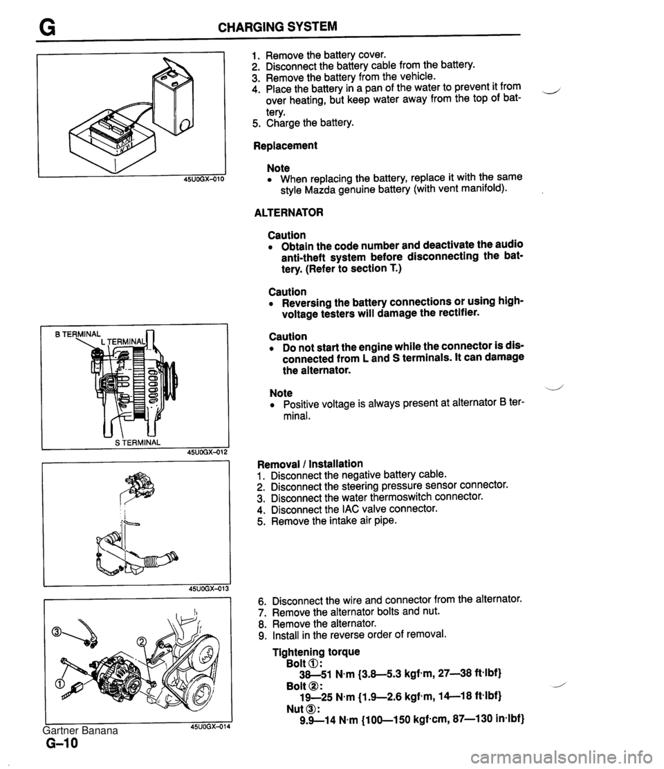
CHARGING SYSTEM B TE S TERMINAL 1. Remove the battery cover. 2. Disconnect the battery cable from the battery. 3. Remove the battery from the vehicle. 4. Place the battery in a pan of the water to prevent it from ,-, over heating, but keep water away from the top of bat- tery. 5. Charge the battery. Replacement Note When replacing the battery, replace it with the same style Mazda genuine battery (with vent manifold). ALTERNATOR Caution Obtain the code number and deactivate the audio anti-theft system before disconnecting the bat- tery. (Refer to section T.) Caution Reversing the battery connections or using high- voltage testers will damage the rectifier. Caution Do not start the engine while the connector is dis- connected from L and S terminals. It can damage the alternator. Note .--,' Positive voltage is always present at alternator B ter- minal. Removal l Installation 1. Disconnect the negative battery cable. 2. Disconnect the steering pressure sensor connector. 3. Disconnect the water thermoswitch connector. 4. Disconnect the IAC valve connector. 5. Remove the intake air pipe. 6. Disconnect the wire and connector from the alternator. 7. Remove the alternator bolts and nut. 8. Remove the alternator. 9. Install in the reverse order of removal. Tightening torque Bolt 0: 38-51 N.m (3.8-5.3 kgf-m, 27-38 ftelbf) Bolt @ : 19-25 N.m j1.9-2.6 kgfem, 14--18 ft-lbf) Nut @I: 9.9--14 N.m (100-150 kgf-cm, 87-1 30 in-lbf) Gartner Banana