1994 MAZDA MX-5 brake
[x] Cancel search: brakePage 947 of 1708

T 2 CRUISE CONTROL SYSTEM PRESS 45UOTX-209 Inspection Procedure Quick inspection 1. Connect a 1.4W test light between terminals D and F, of the cruise control unit connector. u Note There is no wire in terminal D of the connector. Push the test light through the connector and touch the cor- responding pin on the control unit. 2. Turn the ignition switch to ON. 3. Shift the selector lever to D or R range. 4. Verify that the MAlN switch is off. (The MAlN indicator light will be off .) 5. Turn the RESUMEIACCEL switch and the MAlN switch simultaneously to activate the system inspection. The MAlN indicator light will come on. 6. Operate each switch as described below and obtain the problem code numbers. Note The cruise control system will not operate in self-diag- nosis mode. 7. After retrieving the code(s), press the MAlN switch to deactivate the system inspection. The MAlN indicator light will go off. 8. Follow the action corresponding to the problem code. --, Service Code Table Press SETICOAST switch Procedure Press RESUMEIACCEL switch Pattern of output signal (Test light) ON OFF nn M nn Depress brake pedal ON OFF ON Drive vehicle above 40 km/h (25 MPH) Turn ignition switch to ON and shift the selector lever to P or N range (For AT) Depress clutch pedal (For MT) Code No. oN OFF Action lnspect cruise control switch (Refer to page T-106) lnspect cruise control switch (Refer to page T-106) lnspect stoplight switches (Refer to pages T-105 and T-56) lnspect parwneutral switch (Refer to section K) or clutch switch (Refer to page T-105) lnspect vehicle speed sensor or wire harness (Refer to page T-106) Gartner Banana
Page 948 of 1708

CRUISE CONTROL SYSTEM T T P N L JHF B T P N L JHF B CRUISE CONTROL UNIT Removal 1. Remove the passenger side kick panel. 2. Remove the nut and the control unit. Installation Install in the reverse order of removal. Inspection 1. Check the terminal voltages of the control unit. Discon- nect the CIS control unit connector before measuring the voltage at terminal J. 2. If the terminal voltages are correct, replace the control unit. B+: Battery positive voltage berminail Wire color I Connected to I Test condition 1~~ecificationl Action A B C E F (GN) ' (GIB) (G/O) (R) (YIB) G H PCMT (LGIB) J Cruise actuator Cruise actuator Cruise actuator Main switch Main switch (Y) Ignition switch OFF lanition switch ON Main switch OFF Main switch ON Main switch OFF Main switch ON Main switch OFF Main switch ON Main switch OFF Main switch ON Main switch OFF Main switch ON Brake switch (BIL) (BWW) OV B+ Shift to "N" or "P" range Shift to other range Clutch pedal depressed Clutch pedal released ParkINeutral switch Clutch switch OV 9V OV 9V ov 9V B+ OV OV B+ Check AT control unit (Refer to section K) - Brake pedal depressed Brake pedal released Check cruise actuator (Refer to page T-107) Check main switch (Refer to page T-106) OV 5V OV B+ OV 9V Check parWneutral switch (Refer to section K) Check clutch switch (Refer to page T-105) Check brake switch (Refer to page T-105) Gartner Banana
Page 949 of 1708

CRUISE CONTROL SYSTEM B+: Battery positive voltage L rmlnall Wire color M Specification (RIL). . N Action Connected to (G) 0 CELERATOR DAL 9MUOTX-263 Test condition Cruise control switch (Set switch and coast switch) (w) P S T ACTUATOR CABLE Removal 1. Disconnect the actuator cable from the accelerator ped- al. 2. Remove the clamp at the inside of the firewall. (P) 3. Disconnect the actuator cable from the actuator. 4. Remove the clamps and the actuator cable. Main switch ON While turning set switch after main switch ON Check stoplight switch (Refer to page T-105) Stoplight switch Cruise control switch (Resume switch and accel switch) (WIG) (B) Installation Install in the reverse order of removal. Adjustment Remove the clamp and adjust the nut so that actuator cable free play is as shown when the cable is pressed lightly. B+ OV Brake pedal depressed I B+ Main switch ON While turning resume switch after main switch ON Actuator Cable play: 1 .O-3.0mm (0.04--0.12 in) Brake pedal released OV 9V Main switch OFF Main switch ON Vehicle speed sensor Battery GND Check cruise control switch (Refer to page T-106) OV B+ OV Check actuator (Refer to page T-107) Run out betweeno-5V B+ OV rotating rear tires Constant Constant d Check cruise control switch (Refer to page T-106) Check vehicle speed sensor (Refer to page T-106) Repair wire Re~air wire Gartner Banana
Page 950 of 1708

CRUISE CONTROL SYSTEM T BRAKE AND STOPLIGHT SWITCH CLUTCH SWITCH Removal Loosen the locknut and remove the switch. Installation Install in the reverse order of removal. Adjustment Adjust the switch to set the specified pedal height. Pedal height: 175--185mm (6.89-7.82 in) Pedal free play: 0.6-3.lmm (0.02-4.12 in) Inspection 1. Disconnect the clutch switch connector. 2. Check for continuity between terminals of the switch. Pedal position Terminal A B 1 0-a: Continuity Pedal released 3. If not as specified, replace the clutch switch. Pedal de~ressed STOP LIGHTIBRAKE SWITCH Removal Loosen the locknut and remove the switch. 0 I 0 Installation Install in the reverse order of removal. Adjustment Adjust the switch to set the specified pedal height. Pedal height: l7l-l8l mm (6.93--7.13 in) Pedal free play: 4.0-7.0mm (0.16-0.28 in) Inspection 1. Disconnect the brake switch connector. 2. Check for continuity between terminals of the switch. I I I Pedal released I I I Pedal position w: Continuity Terminal Pedal depressed 3. If not as specified, replace the brake switch. 4. If the switch is OK, repair the wiring harness (fuse - brake switch - control unit). A 0 I 0 B Gartner Banana
Page 1117 of 1708

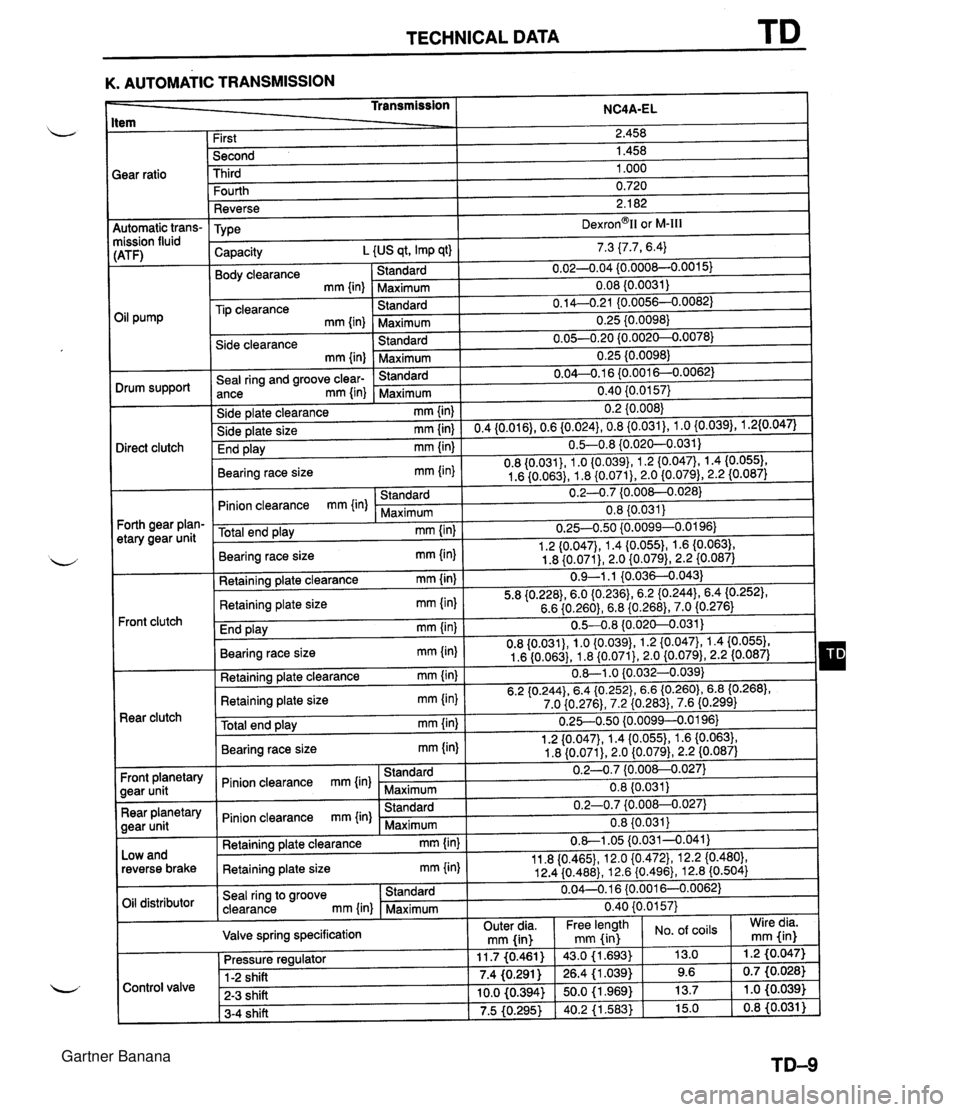
TECHNICAL DATA K. AUTOMATIC TRANSMISSION tem Transmission ;ear ratio NC4A-EL 4utomatic trans- nission fluid :ATF) 3il pump Drum support Direct clutch Forth gear plan- etary gear unit Front clutch Rear clutch Front planetary gear unit Rear planetary gear unit Low and reverse brake Oil distributor First Second Third Fourth Reverse TY pe Capacity L {US qt, Imp qt) Body clearance Standard mm {in) -Maximum Tip clearance Standard mm {in) Maximum Side clearance Standard mm {in) Maximum Seal ring and groove clear- Standard ance mm {in) Maximum Side plate clearance mm {in) Side plate size mm{in) End play mm {in) Bearing race size mm {in) Standard Pinion clearance mm {in) Maximum Total end play mm {in) Bearing race size mm (in) Retaining plate clearance mm {in) Retaining plate size mm {in) End play mm (in) Bearing race size mm {in) Retaining plate clearance mm {in) Retaining plate size mm {in) Total end play mm {in) Bearing race site mm {in) Standard Pinion clearance rnm {in) Maximum Standard Pinion clearance mm {in) Maximum Retaining plate clearance mm {in) Retaining plate size mm {in) Seal ring to groove Standard clearance mm {in) Maximum Valve spring specification 2.458 1.458 1 .OOO 0.720 2.1 82 ~exron~ll or M-Ill 7.3 {7.7, 6.4) 0.02-0.04 {0.000&0.0015) 0.08 (0.0031) 0.14--0.21 IO.0056--0.0082) 0.25 {0.0098) 0.05-0.20 {0.0020--0.0078) 0.25 {0.0098) 0.04-0.1 6 {0.0016--0.0062) - - 0.40 {0.0157) 0.2 {0.008) 0.4{0.016),0.6{0.024},0.8{0.031),1.0{0.039),1.2{0.047) 0.5-0.8 {0.020--0.031) 0.8 {0.031), 1 .O {0.039}, 1.2 (0.0471, 1.4 {0.055), 1.6 {0.063), 1.8 {0.071), 2.0 {0.079), 2.2 {0.087) 0.2-0.7 {0.008-0.028) 0.8 {0.031} 0.254.50 {0.0099-0.0196) 1.2 {0.047}, 1.4 (0.0551, 1.6 {0.063), 1.8 {0.071), 2.0 {0.079), 2.2 {0.087) 0.9-1.1 {0.036-4.043) 5.8 {0.228),6.0 (0.2361, 6.2 (0.2443, 6.4 (0.2521, 6.6 {0.260), 6.8 {0.268),7.0 {0.276) 0.5-4.8 {0.020-0.031) 0.8 {0.031), 1.0 {0.039), 1.2 {0.047), 1.4 {0.055}, 1.6 (0.063), 1.8 {0.071}, 2.0 (0.079), 2.2 (0.087) 0.-1 .O iO.032-0.039) 6.2 {O.244},6.4 {O.252}, 6.6 (0.2601, 6.8 (0.2681, 7.0 {0.276), 7.2 {0.283), 7.6 (0.299) 0.25-0.50 {0.0099--0.0196} 1.2 {0.047}, 1.4 {0.055), 1.6 {0.063), 1.8 {0.071), 2.0 {0.079}, 2.2 I0.087) 0.2-0.7 {0.008--0.027) 0.8 (0.031j 0.2-0.7 {0.00&0.027) 0.8 {0.031} 0.8-1.05 {0.031-0.041) 11.8 I0.4651, 12.0 {0.472}, 12.2 {0.480}, 12.4 {0.488}, 12.6 {0.496}, 12.8 (0.504) 0.04--0.16 (0.001 6--0.0062) 0.40 {0.0157) Control valve . . 11.7 (0.461) 7.4 (0,291 ) 10.0 (0.394) 7.5 (0.295) Pressure regulator 1-2 shift - 2-3 shift 3-4 shift Wire dia. mm fin) Outer dia. mm fin) . . 43.0 (1.693) 26.4 (1 .039) 50.0 (1.969) 40.2 (1.563) Free length mm (in of coils 13.0 9.6 13.7 15.0 -. 1.2 (0.047) 0.7 (0.026) 1 .O (0.039) 0.8 (0.031 ) Gartner Banana
Page 1118 of 1708

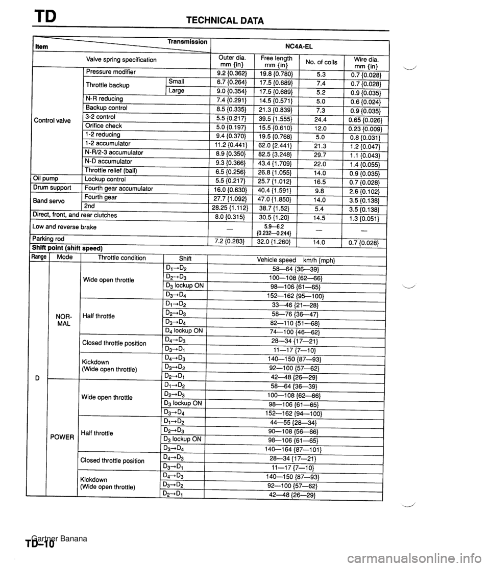
TECHNICAL DATA Mode NOR- MAL 4 POWER - Transmission Item _5 Valve spring specification . , Throttle condition NC4A-EL Control valve Oil pump Drum support Band servo Wide open throttle Outer dia. mm {in) 9.2 (0.362) 6.7 {0.264) 9.0 (0.354) 7.4 (0.291) 8.5 (0.335) 5.5 (0.21 7) 5.0 (0.1971 9.4 (0.370) 11.2 i0.441) 8.9 (0.350) 9.3 (0.366) 6.5 (0.256) 5.5 {0.217) 16.0 (0.630) 27.7 {I .092) 28.25 (1.11 2) 8.0 (0.31 5) - 7.2 (0.283) Half throttle Direct, front, and rear clutches Low and reverse brake Parking rod Shift point (shift s~eed) Pressure modifier - - -- Closed throttle position Kickdown (Wide open throttle) Free length rnm {in) 19.8 (0.780) 17.5 (0.689) 17.5 (0.689) 14.5 (0.571) 21.3 (0.839) 39.5 {I .555) 15.5 {0.610} 19.5 (0.768) 62.0 (2.441) 82.5 (3.248) 43.4 {I .709) 26.8 11.055) 25.7 (1.012) 40.4 (1.591) 47.0 {I .850) 38.7 {I .52) 30.5 {I .20) 5.9-6.2 (0.2324.244) 32.0 {I .260) Throttle backup Wide open throttle Half throttle Small Large Closed throttle position No. of coils 5.3 7.4 5.2 5.0 7.3 24.4 12.0 5.0 21.3 29.7 22.0 14.0 16.5 9.8 14.0 5.4 14.5 - 14.0 N-R reducing Backup control 3-2 control Orifice check 1-2 reducing 1-2 accumulator N-W2-3 accumulator N-D accumulator Throttle relief (ball) Lockup control Fourth gear accumulator Fourth gear 2nd Kickdown (Wide open throttle) Wire dia. mm {in) 0.7 (0.028) 0.7 (0.028) 0.9 (0.035) 0.6 (0.024) 0.9 (0.035) 0.65 (0.026) 0.23 {0.009) 0.8 (0.031) 1.2 t0.047) 1.1 (0.043) 1.4 (0.055) 0.9 (0.035) 0.7 (0.028) 2.6 {0.102) 3.5 (0.1 38) 3.5 (0.1 38) 1.3 (0.051) - 0.7 (0.028) d Shift I D1-+D2 I D2+D3 D3 lockup ON D3+D4 b-+D2 - Vehicle speed kmlh (mph) 58-64 (36-39) 1 OQ108 (62-46) 9&106 (61-65) 152-1 62 (9%100) 3346 (21 -28) D2-*D3 '33434 D4 lockup ON D4-+b 0i-t~~ D2*D3 03 lockup ON D3-D4 58-76 (36-47) 82-1 1 0 (5 1-48} 74-1 00 (46--62) 28-34 (1 7-21 ) 44--55 {2&34) 90-1 08 (5666) 9&106 (61-65) 14-1 64 (87-1 01) Gartner Banana
Page 1121 of 1708

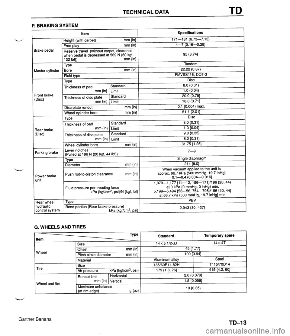
TECHNICAL DATA TD P. BRAKING SYSTEM 3rake pedal Waster cylinder 'ront brake :Disc) Rear brake [Disc) Parking brake Power brake unit Rear wheel hydraulic control system -. . . . . Free play mm {in) I 4--7 {0.16--0.28) Item Heiaht (with car~et) mm {in) Reserve travel (without carpet, clearance when pedal is depressed at 589 N (60 kgf, Specifications 171-1 81 {6.73-7.13) . ,~ I Bore mm {in} I 22.22 (0.87) 132 Ibi)) mm {in) 1 Tv~e Tandem . . Fluid type Type Disc plate runout mm {in) [ 0.1 {0.004) max. Wheel cvlinder bore mm {in) I 51.1 i2.011 . . FMVSS116, DOT-3 Disc ~hickness of pad mm {in) Thickness of disc plate mm {in) I I . . Wheel cylinder bore mm {in) I 31.75 (1.25) Standard Limit .%mhd Limit Lever notches 1 7 n 8.0 I0.31) 1 .O (0.041 20.0 {0.79) 18.0 {0.71} . . Disc 8.0 {0.31) 1 .O i0.04) 9.0 10.35) . , TY pe Thickness of pad mm {in) Thickness of disc plate Tvoe I Sinale diawhraam Standard Limit &mdard mm {in) (Pulled at 196 N (20 kgf, 44 Ibf)) ,r- I " . - Diameter mm {in) I 21 4 (8.0) Limit 1-3 Push rod-to-piston clearance mm (in) When vacuum applied to the unit is approx. 66.7 kPa (500 mmHg, 19.7 inHg} 0.1-0.4 (0.004--0.016) Fluid pressure per treading force kPa {kgf/cm2, psi)/N {kgf, Ibf) Tv~e Q. WHEELS AND TIRES 1,079-1,177 {ll-12, 15&171)/196 (20,441 at 0 kPa 10 mmHg, 0 inHg) min. 5,199~5,494 {53-56, 754--796)/196 {20, 44) at 66.7 kPa (500 mmHg, 19.7 inHg} min. PBV Bend portion (Rear brake pressure) kPa {kgf/cm2, psi) 2,943 {30,427) Wheel Temporary spare 14x4T TY Pe ltem 1 Size Standard 14x5 112-JJ Offset mm {in) Pitch circle diameter mm {in) Material Tire Wheel and tire I 45 {I .77) 100 (3.94) Aluminum allov Steel Size Air pressure kPa {kgf/cm2, psi) 185/60R14 82H 179 11.8, 26) Runout limit mm {in) 1 TI 1 5/70D1 4 41 5 (4.2, 60) Horizontal Vertical 2.0 {0.079) 1.5 10.059) 10 (0.35) Maximum unbalance (at rim edge) 9 {oz) Gartner Banana
Page 1123 of 1708

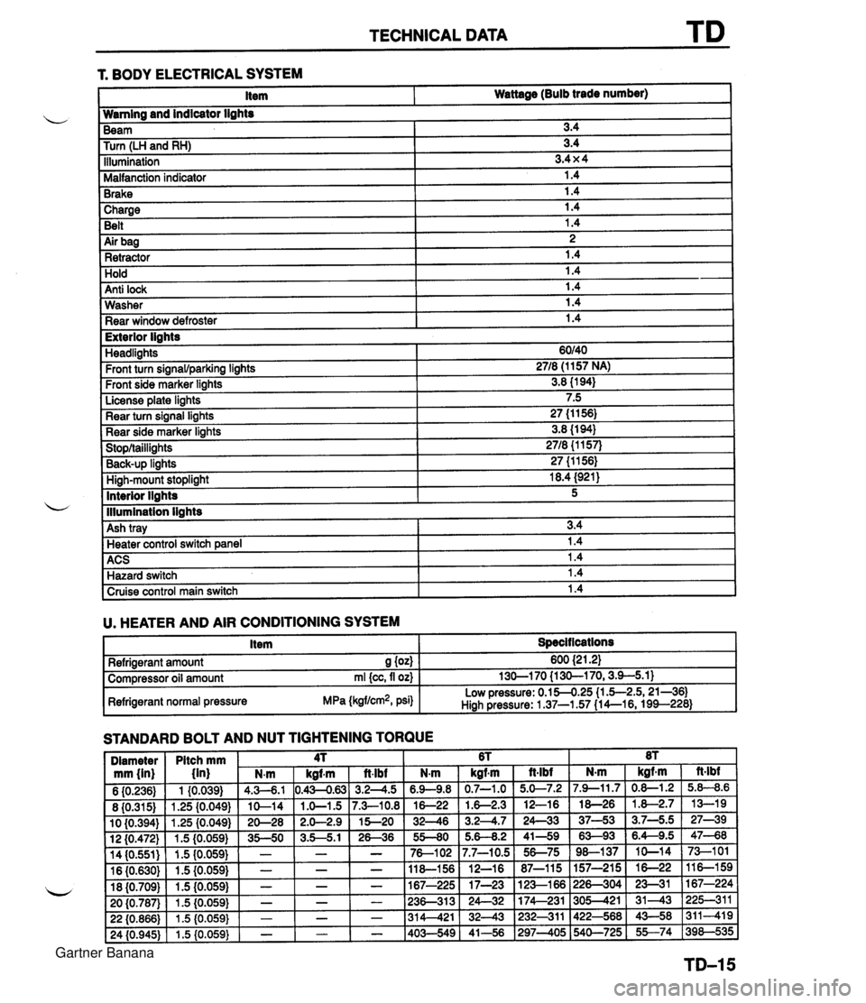
TECHNICAL DATA 1 Charge I 1.4 Belt 1.4 r. BODY ELECTRICAL SYSTEM 1 Air bag I 2 1 Retractor 1.4 Item Wattage (Bulb trade number) Hold Anti lock Wamlng and indicator lights 1.4 1.4 Washer Rear window defroster Beam Turn (LH and RH) Illumination Malfanction indicator Brake 1.4 1.4 I Exterior lights 3.4 3.4 3.4 x 4 1.4 1.4 Headlights Front turn signawparking lights Front side marker lights License plate lights Rear turn signal lights Rear side marker lights Stop/taillights Back-UP linhts High-mount stoplight I 18.4 (921) ACS 1 1.4 Hazard switch 1.4 60140 2718 (1 157 NA) 3.8 (1 94) 7.5 27 (1 1 56) 3.8 (1 94) 2718 {I 157) 27 (1 1561 Interior llahts - I lllumination lights I Cruise control main switch I 1.4 I 5 Ash tray U. HEATER AND AIR CONDITIONING SYSTEM I Item I Specit lcations I 3.4 Heater control switch ane el I 1.4 STANDARD BOLT AND NUT TIGHTENING TORQUE Refrigerant amount S (04 Compressor oil amount rnl {cc, fl oz) Refrigerant normal pressure MPa (kgflcm2, psi) 600 {2 1.21 130-1 70 {I 30-1 70,3.9-5.1) Low pressure: 0.154.25 (1 .5-2.5,21-361 Hiah Pressure: 1 37-1.57 (1 4--16, 199--228) Gartner Banana