Page 475 of 1708
TRANSMISSION 15. Apply ATF to the outer race, and install the outer race so that the toothless area is in line with the lubrication hole in the direct clutch drum. d 16. Apply ATF to the one-way clutch, and install it into the outer race. Verify that the spring cage of the one-way clutch faces toward the direct clutch drum. 17. Apply ATF to the side plate, and install the side plate so that the toothless area is in line with the lubrication hole in the direct clutch drum. 18. Install the snap ring. 19. Apply petroleum jelly to the bearing, and install it onto the direct clutch drum. Bearing outer diameter: 70.0mm (2.756 in) 20. Measure the clearance between the side plate and the snap ring with a feeler gauge. If not within specification, adjust the clearance by installing the correct side plate. Clearance Maximum: 0.2mm (0.008 in) Side plate sizes mm {in) - Gartner Banana
Page 487 of 1708
K TRANSMISSION FRONT CLUTCH Preparation SST Preinspection Front clutch operation 1. Install the front clutch onto the drum support along with the seal rings. Apply compressed air through the oil pas- sage as shown. 49 0378 375 Compressor, clutch spring Air pressure: 392 kPa (4.0 kglcm*, 57 psi} max. For removal / installation of front clutch 2. Verify that the retaining plate moves toward the snap ring. If not, the seal ring or O-ring may be damaged or fluid may be leaking at the piston check ball. Inspect them, and replace when assembling. Clearance between retaining plate and snap ring Measure the clearance between the retaining plate and the snap ring. Clearance: 0.9--1 .l mm (0.036-0.043 in} .--- Select and install the correct retaining plate when as- sembling. Gartner Banana
Page 492 of 1708
TRANSMISSION K REARCLUTCH Preparation SST Preinspection Rear clutch operation 1, Install the rear clutch onto the drum support along with the seal rings. Apply compressed air through the oil pas- sage as shown. i/' Air pressure: 392 kPa {4.0 kg/cm2,57 psi} max. 2. Verify that the retaining plate moves toward the snap ring. If not, the seal ring or O-ring may be damaged or fluid may be leaking at the piston check ball. Inspect them, and replace when assembling. 49 0378 375 Compressor, clutch spring Clearance between retaining plate and snap ring Measure the clearance between the retaining plate and the snap ring. For removal / installation of rear clutch Clearance: 0.8-1.0mm (0.0324.039 in) Adjust the clearance by installing the correct retaining plate. Gartner Banana
Page 501 of 1708
K TRANSMISSION CLEARANCE Inspection Rear planetary pinion carrier 1. Measure the clearance between the pinion washer and the planetary pinion carrier. d Clearance Standard : 0.2--0.7mm (0.008-4.027 in) Maximum : 0.8mm (0.031 in) 2. If not within specification, replace the planetary pinion carrier. Assembly procedure 1. Install the snap ring into the connecting drum. 2. Apple ATF to the one-way clutch. Install it into the con- necting drum, with the arrow pointing toward the front. 3. Apply ATF to the drive flange and internal gear, and install it into the internal gear. 4. Install the snap ring. 5. Apple petroleum jelly to the bearing, and install it onto the drive flange. Bearing outer diameter: 47.0mm (1.850 in) 6. Install the internal gear and the drive flange into the con- necting drum. 7. Apple petroleum jelly to the bearing, and install it onto the drive flange with the black surface facing upward. Bearing outer diameter: 70.0mm (2.756 in) Gartner Banana
Page 503 of 1708
K TRANSMISSION LOW AND REVERSE BRAKE Preparation SST Preinspection Low and reverse brake operation 1. Apply compressed air through the oil passage as shown. 49 0378 346 Hex head wrench Air pressure: 392 kPa (4.0 kglcm2, 57 psi) max. For removal I installation of one-way clutch 2. Verify that the retaining plate moves toward the snap ring. If not, the seal ring or O-ring may be damaged or fluid may be leaking at the piston check ball. Inspect them, and replace as necessary when assembling. Clearance between retaining plate and snap ring 1. Measure the clearance between the retaining plate and the snap ring. Clearance: 0.8-1.05mm (0.032--0.041 in) i/ 2. Select and install the correct retaining plate when as- sembling. Gartner Banana
Page 619 of 1708
M DIFFERENTIAL Disassembly note Output shafts Remove the output shafts with two pry bars as shown in the figure. -J Differential case Caution The differential case is made of aluminum, and is therefore easily dented and scratched by metal tools. When. separating the differential carrier from the case, use only a plastic hammer at the point shown in the figure. Strike the differential carrier with a copper hammer to separate it from the case. Differential gear assembly Mount the differential gear assembly on the SST. Bearing caps Mark one bearing cap and the carrier. Adjusting nuts Mark one adjusting nuts and the carrier. Knock pin Secure the gear case in a vise and tap out the knock pin toward the ring gear side. Bearing inner races (Side bearing) Note Mark the bearings so that they can later be reinstalled in the same position. Remove the bearing inner races (side bearing) from the gear case by using the SST. -1 Gartner Banana
Page 643 of 1708

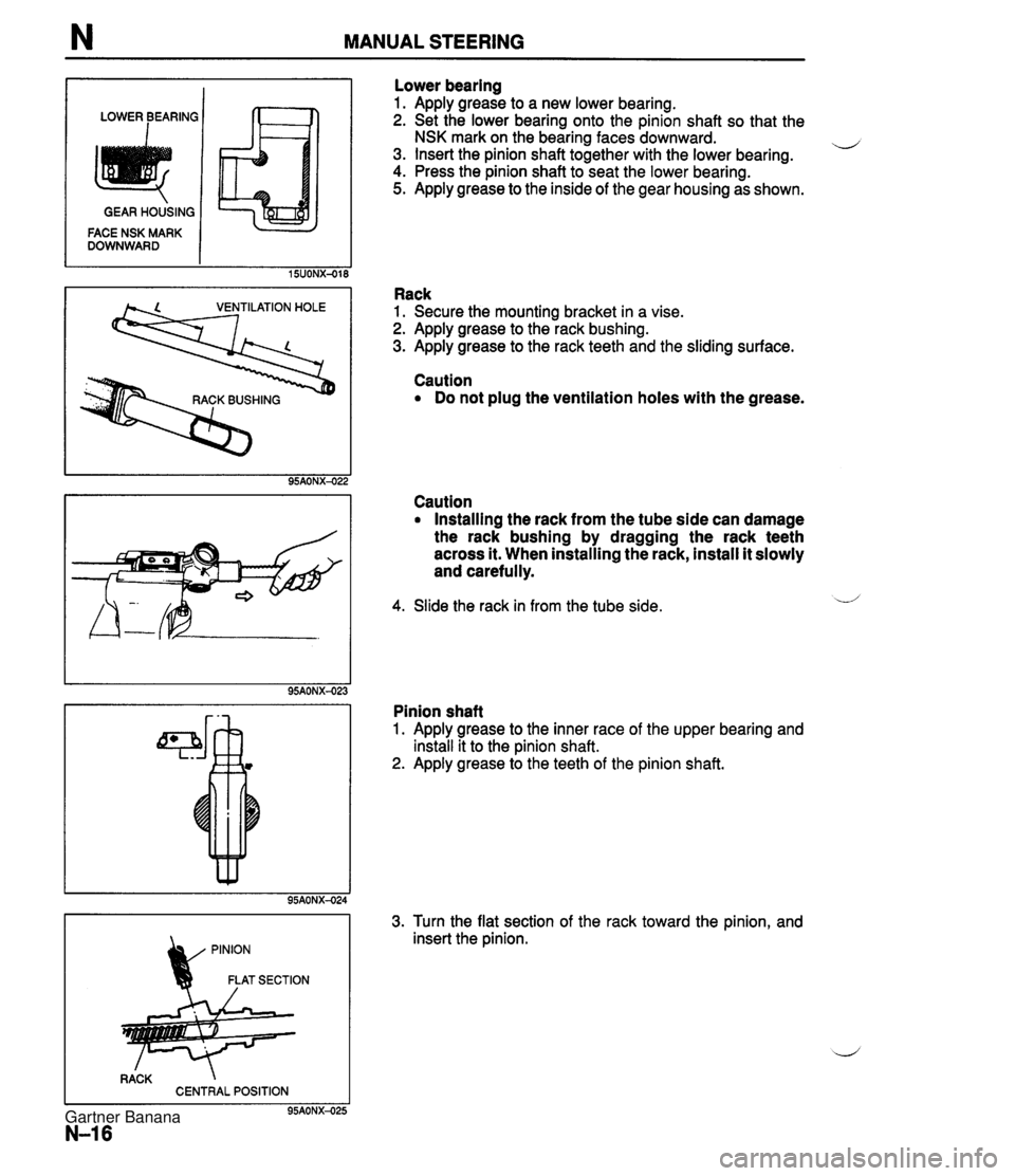
N MANUAL STEERING LOWER BEARING 1 IT-71 GEAR HOUSING FACE NSK MARK DOWNWARD 15UONX-018 VENTILATION HOLE 95AONX-02; RACK CENTRAL POSITION 95AONX-025 N-16 Lower bearing 1. Apply grease to a new lower bearing. 2. Set the lower bearing onto the pinion shaft so that the NSK mark on the bearing faces downward. u 3. Insert the pinion shaft together with the lower bearing. 4. Press the pinion shaft to seat the lower bearing. 5. Apply grease to the inside of the gear housing as shown. Rack 1. Secure the mounting bracket in a vise. 2. Apply grease to the rack bushing. 3. Apply grease to the rack teeth and the sliding surface. Caution Do not plug the ventilation holes with the grease. Caution Installing the rack from the tube side can damage the rack bushing by dragging the rack teeth across it. When installing the rack, install it slowly and carefully. 4. Slide the rack in from the tube side. Pinion shaft 1. Apply grease to the inner race of the upper bearing and install it to the pinion shaft. 2. Apply grease to the teeth of the pinion shaft. 3. Turn the flat section of the rack toward the pinion, and insert the pinion. Gartner Banana
Page 686 of 1708

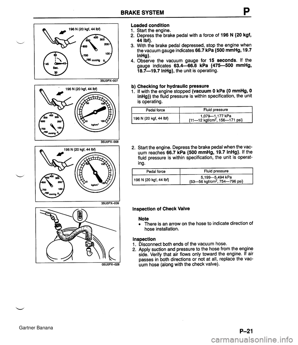
BRAKE SYSTEM P (20 kgf, 44 Ibf) (20 kgf, 44 Ibf) Loaded condition 1. Start the engine. 2. Depress the brake pedal with a force of 196 N (20 kgf, 44 Ibf). 3. With the brake pedal depressed, stop the engine when the vacuum gauge indicates 66.7 kPa I500 mmHg, 19.7 inHg). 4. Observe the vacuum gauge for 15 seconds. If the gauge indicates 63.4-66.6 kPa (475--500 mmHg, 18.7-19.7 inHg), the unit is operating. b) Checking for hydraulic pressure 1. If with the engine stopped (vacuum 0 kPa (0 mmHg, 0 inHg}) the fluid pressure is within specification, the unit is operating. 1 Pedal force Fluid pressure 2. Start the engine. Depress the brake pedal when the vac- uum reaches 66.7 kPa (500 mmHg, 19.7 inHg). If the fluid pressure is within specification, the unit is operat- ing. 1 96 N {20 kgf, 44 Ibf) I Pedal force I Fluid pressure I 1,079-1,177 kPa {I 1-1 2 kgf/cm2, 156-1 71 psi) lnspection of Check Valve 196 N {20 kgf, 44 Ibf) Note There is an arrow on the hose to indicate direction of hose installation. 5,199--5,494 kPa {53-56 kgf/cm2, 754--796 psi} lnspection 1. Disconnect both ends of the vacuum hose. 2. Apply suction and pressure to the hose from the engine side. Verify that air flows only toward the engine. If air passes in both directions or not at all, replace the vac- uum hose (along with the check valve). Gartner Banana