Page 884 of 1708

WARNING LIGHT AND SENDER UNIT T OHMMETER Washer Level Indicator lnspection 1. Disconnect the connector from the washer level sensor. 2. Jump terminal-wire L (harness side) to a body ground. 3. Start the engine and check that the WASHER indicator illuminates. 4. If there is no illumination, check the bulb, wiring harness, and sensor. Replace or repair as necessary. Washer Level Sensor lnspection 1. Connect the sensor connector (sensor side) to an ohm- meter. 2. Move the sensor float up and down. 3. Verify that there is continuity when the float is at the low- est point. BRAKE FLUID LEVEL SENSOR lnspection 1. Check for continuity of the sensor. 2. If continuity is not as specified, replace the level sensor. Float level Below MIN Above MIN BUCKLE SWITCt Continuity Yes No OHMMETER -1 PARKING BRAKE SWITCH lnspection 1. Disconnect the parking brake switch connector. 2. Check for continuity between the switch connector and ground. I Lever I Continuity I 3. If continuity is not as specified, adjust or replace the parking brake switch. (Refer to section P.) Pulled one notch Released BUCKLE SWITCH lnspection 1. Disconnect the buckle switch connector 2. Check for continuity of the switch. Yes No Seat belt I Continuity Seat belt buckled Seat belt unbuckled No Yes 3. If continuity is not as specified, replace the buckle switch. Gartner Banana
Page 918 of 1708

LIGHTING SYSTEM T Symptom: Daytime running lights (DRL) do not illuminate. (Turn signals function normally.) DRL operate with engine running and following switches are off: Headlight switch Turn signal switch (Selected turn signal light flashes, other light remains illumi- nated) Hazard warning switch Parking brake switch (Parking brake released) Step 1 1. Position the vehicle on a flat surface and block the wheels to prevent vehicle movement. 2. Turn the ignition switch to ON. 3. Measure the voltage at the following terminal wires of the DRL control unit. 4. If correct, replace the DRL control unit. B+: Battery positive voltage Step 2 1. Disconnect the parking brake switch connector. 2. Check for continuity between the terminal of the switch and a body ground. Terminal J (L) u Connected to WIPER 20A fuse I(B) B (R) C (WIR) Parking brake lever Pulled one notch Continuity Yes Released Test condition Constant GND Parking brake switch Headlight switch No I 3. If not as specified, adjust or replace the parking brake switch. 4. If correct, repair wiring harness. (DRL control unit - Parking brake switch) Specification B+ Constant Parking brake released Headlight switch off Action Repair wiring harness (WIPER 20A - DRL control unit) Other B+ Other Repair wiring harness (DRL control unit - GND) Go to Step 2 Go to Step 3 Gartner Banana
Page 944 of 1708

CRUISE CONTROL SYSTEM Step 8 - lnspection of actuator 1. Measure the cruise actuator solenoid resistance by us- ing an ohmmeter. Check terminals C-A 2. If not as soecified. redace the actuator. Resistance C-B C-D 3. If continuiiv is OK: ad to Ster, 84. Approx. 25 to 55R 4. ~isconne4 the actiator cabie from the accelerator ped- al. 5. Run the engine at idle speed. 6. Apply battery positive voltage to the following terminals, and check actuator operation. B+: Batterv aositive voltaae I Order 1 2 7. If not as specified, replace the actuator. Terminal condition AlBlClD 3 4 Step 9 - lnspection of vehicle speed sensor 1. Remove the instrument cluster. 2. Check for continuity between terminals 2D and 2F while rotating the speedometer cable. 3. If there are not four pulses per shaft rotation, replace the vehicle speed sensor. (Refer to page T-32.) 4. If there are four pulses per rotation, check the wiring har- ness. (instrument cluster - control unit). 5. If the wiring is OK, replace the cruise control unit. Operation of control cable GND GND GND - GND - - B+ B+ B+ - GND GND Pull Hold - - Extend Release Gartner Banana
Page 952 of 1708
CRUISE CONTROL SYSTEM T ACTUATOR Inspection 1. Measure the actuator solenoid resistance by using an ohmmeter. Check terminals C-A 2. If not as specified, replace the actuator. 3. Disconnect the actuator cable from the accelerator ped- al. 4. Run the engine at idle speed. 5. Apply battery positive voltage to the following terminals, and check the actuator operation. Resistance C-B C-D B+: Battery positive voltage Approx. 25 to 55hL I I I I I 1 I GND I GND I B+ I GND 1 Pull I Terminal condition AlBlClD I I I 1 I 2 1 GND I - I B+ I GND I Hold I Operation of control cable I 6. If not as specified, replace the actuator. 3 4 Removal 1. Disconnect the accelerator cable and vacuum hose from the actuator. 2. Remove the bolt and nuts and the actuator. Installation Install in the reverse order of removal. GND - - - B+ - - - Extend Release Gartner Banana
Page 1035 of 1708

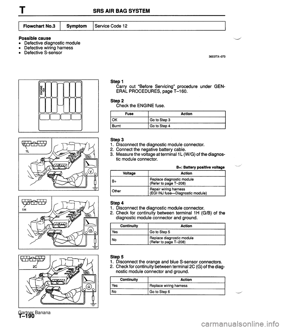
T SRS AIR BAG SYSTEM Possible cause ij Defective diagnostic module Defective wiring harness Defective S-sensor Step 1 Carry out "Before Servicing" procedure under GEN- ERAL PROCEDURES, page T-1 60. Service Code 12 Flowchart No.3 Step 2 Check the ENGINE fuse. Fuse Action I Symptom Step 3 1. Disconnect the diagnostic module connector. 2. Connect the negative battery cable. 3. Measure the voltage at terminal 1 L (WIG) of the diagnos- OK Burnt tic module connector. Go to Step 3 Go to Step 4 B+: Battery positive voltage - Other Repair wiring harness iEGI INJ fuss-Diaanostic module1 I Voltage B+ -- ~ Action Replace diagnostic module (Refer to page T-208) I NO Replace diagnostic module (Refer to Daae T-2081 Step 4 1. Disconnect the diagnostic module connector. 2. Check for continuity between terminal 1 H (GIB) of the diagnostic module connector and ground. Step 5 1. Disconnect the orange and blue S-sensor connectors. 2. Check for continuity between terminal 2C (G) of the diag- nostic module connector and ground. 1 Continuity Action 1 Continuity Yes Action Go to Step 5 Yes No Replace wiring harness Go to Step 6 L Gartner Banana
Page 1069 of 1708

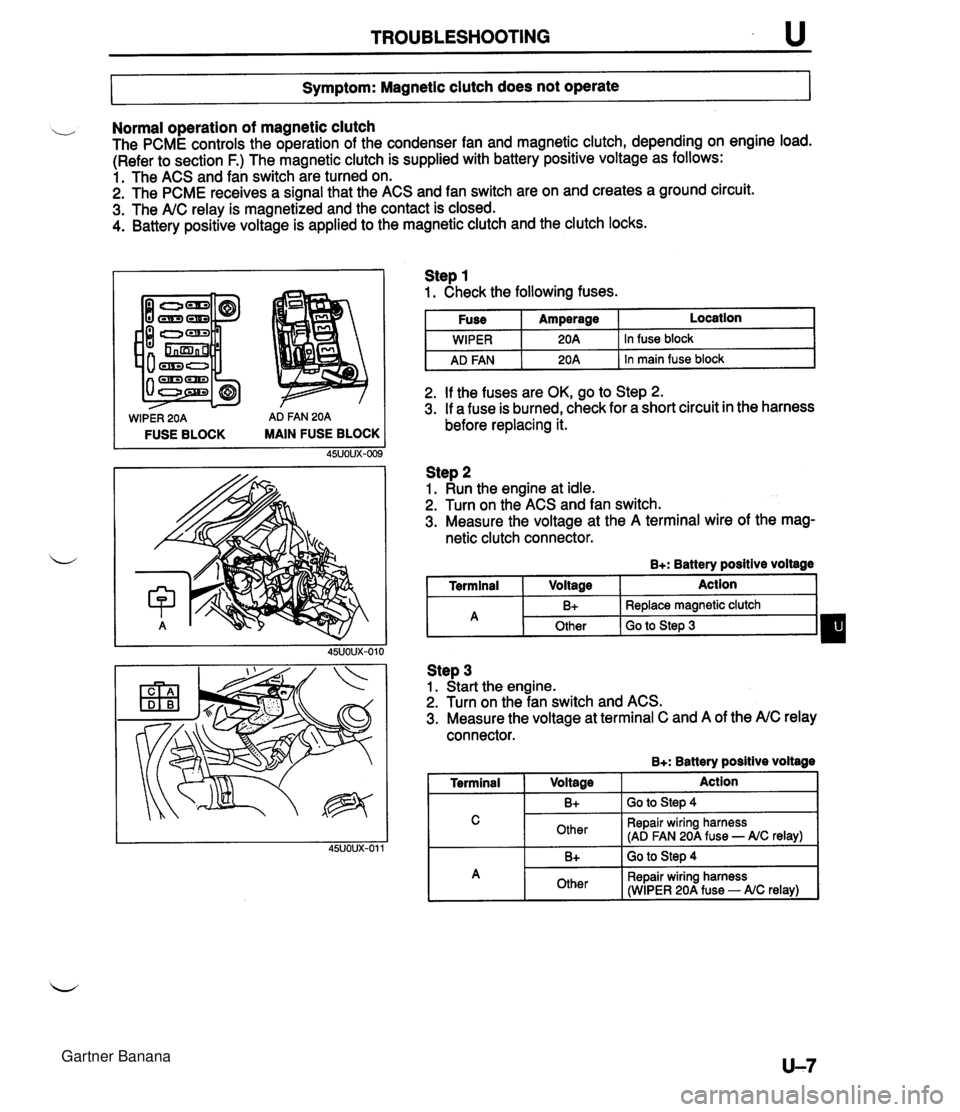
TROUBLESHOOTING u 7- Symptom: Magnetic clutch does not operate I Normal operation of magnetic clutch The PCME controls the operation of the condenser fan and magnetic clutch, depending on engine load. (Refer to section F.) The magnetic clutch is supplied with battery positive voltage as follows: 1. The ACS and fan switch are turned on. 2. The PCME receives a signal that the ACS and fan switch are on and creates a ground circuit. 3. The A/C relay is magnetized and the contact is closed. 4. Battery positive voltage is applied to the magnetic clutch and the clutch locks. WIPER 20A AD FAN 20A FUSE BLOCK MAIN FUSE BLOCK Step 1 1. Check the following fuses. I Fuse I Amperage I Location I I I . - I WIPER I 20A 1 In fuse block I I AD FAN I 20A 1 In main fuse block I 2. If the fuses are OK, go to Step 2. 3. If a fuse is burned, check for a short circuit in the harness before replacing it. Step 2 1. Run the engine at idle. 2. Turn on the ACS and fan switch. 3. Measure the voltage at the A terminal wire of the mag- netic clutch connector. B+: Battery positive voltage I Terminal I Voltage I Action 1 Step 3 1. Start the engine. 2. Turn on the fan switch and ACS. 3. Measure the voltage at terminal C and A of the A/C relay connector. B+: Batterv positive voltaae - -- A 1 Terminal I V0lta0e 1 Action I I C I Other I Repair wiring harness (AD FAN 20A fuse - AIC relay) I B+ Other I 1. -. B+ I GO to step 4 Replace magnetic clutch Go to Step 3 I A 1 Other I Repair wiring harness (WIPER 20A fuse - AIC relay) I Gartner Banana
Page 1071 of 1708

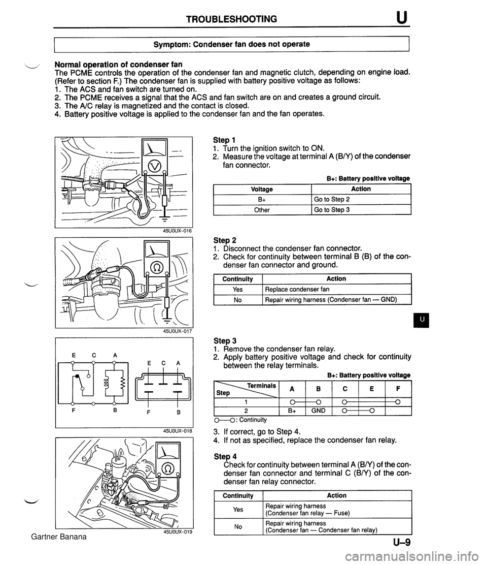
TROUBLESHOOTING u Symptom: Condenser fan does not operate Normal operation of condenser fan The PCME controls the operation of the condenser fan and magnetic clutch, depending on engine load. (Refer to section F.) The condenser fan is supplied with battery positive voltage as follows: 1. The ACS and fan switch are turned on. 2. The PCME receives a signal that the ACS and fan switch are on and creates a ground circuit. 3. The A/C relay is magnetized and the contact is closed. 4. Battery positive voltage is applied to the condenser fan and the fan operates. Step 1 1. Turn the ignition switch to ON. 2. Measure the voltage at terminal A (B/Y) of the condenser fan connector. B+: Battery positive voltage Step 2 1. Disconnect the condenser fan connector. 2. Check for continuity between terminal B (B) of the con- denser fan connector and ground. Voltage B+ Other I GO to step 3 Action Go to Step 2 I continuity I Action I Step 3 1. Remove the condenser fan relay. 2. Apply battery positive voltage and check for continuity between the relay terminals. B+: Battery positive voltage Yes No Replace condenser fan Repair wiring harness (Condenser fan - GND) M: Continuity - - - 3. If correct, go to Step 4. 4. If not as specified, replace the condenser fan relay. 1 0 2 B+ Step 4 Check for continuity between terminal A (BN) of the con- denser fan connector and terminal C (BN) of the con- denser fan relay connector. I Continuity I Action 1 Repair wiring harness (Condenser fan relay - Fuse) B 0 GND I Repair wiring harness (Condenser fan - Condenser fan relay) I C 0 0 E 0 F 0 Gartner Banana
Page 1072 of 1708

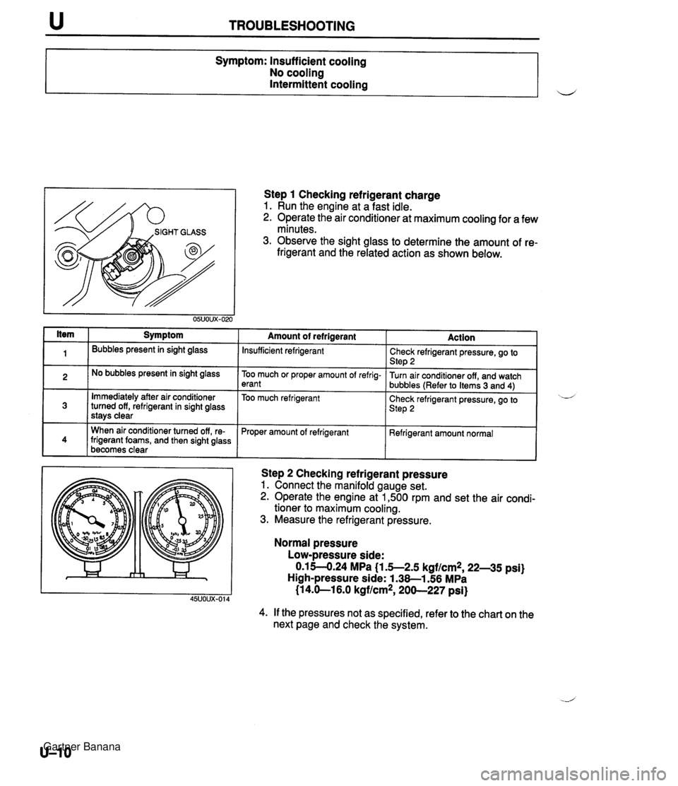
TROUBLESHOOTING I ltem 1 Symptom Symptom: lnsuff icient cooling No cooling Intermittent cooling Ill Bubbles present in sight glass u Immediately after air conditioner turned off, refrigerant in sight glass stavs clear I. When air conditioner turned off, re- frigerant foams, and then sight glass becomes clear No bubbles present in sight glass Step 1 Checking refrigerant charge 1. Run the engine at a fast idle. 2. Operate the air conditioner at maximum cooling for a few minutes. 3. Observe the sight glass to determine the amount of re- frigerant and the related action as shown below. Amount of refrigerant Action Insufficient refrigerant Too much or proper amount of refrig- erant Too much refrigerant Step 2 Checking refrigerant pressure 1. Connect the manifold gauge set. 2. Operate the engine at 1,500 rpm and set the air condi- tioner to maximum cooling. 3. Measure the refrigerant pressure. 1 Proper amount of refrigerant Normal pressure Low-pressure side: 0.1 5-4.24 MPa (1.5--2.5 kgf/cm2, 22--35 psi) High-pressure side: 1.38-1.56 MPa (1 4.0-1 6.0 kgf/cm2, 200-227 psi) Check refrigerant pressure, go to Step 2 Turn air conditioner off, and watch bubbles (Refer to Items 3 and 4) Check refrigerant pressure, go to Step 2 Refrigerant amount normal 4. If the pressures not as specified, refer to the chart on the next page and check the system. ,d Gartner Banana