1994 MAZDA MX-5 check engine
[x] Cancel search: check enginePage 1076 of 1708
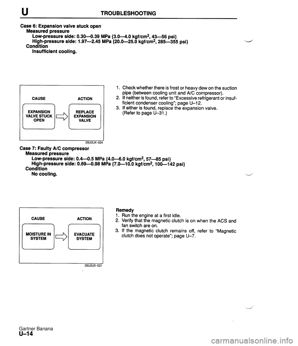
u TROUBLESHOOTING Case 6: Expansion valve stuck open Measured pressure Low-pressure side: 0.30-0.39 MPa {3.0-4.0 kgf/cm2, 43-56 psi) High-pressure side: 1.97-2.45 MPa (20.0-25.0 kgf/cm2, 285-355 psi) Condition Insufficient cooling. CAUSE ACTION 7 m EXPANSION REPLACE / VALWEiUCK I *I EXPANSION VALVE Case 7: Faulty AIC compressor Measured pressure 1. Check whether there is frost or heavy dew on the suction pipe (between cooling unit and AIC compressor). 2. If neither is found, refer to "Excessive refrigerant or insuf- ficient condenser cooling"; page U-12. 3. If either is found, replace the expansion valve. (Refer to page U-31.) LOW-pressure side: 0.4-0.5 MPa (4.0-6.0 kgf/cm2, 57-85 psi) High-pressure side: 0.69-0.98 MPa (7.0-10.0 kgflcm2, 100-1 42 psi) Condition No cooling. I 1 Remedy CAUSE ACTION MOISTURE IN 1. Run ihe engine at a first idle. 2. Verify that the magnetic clutch is on when the ACS and fan switch are on. 3. If the magnetic clutch remains off, refer to "Magnetic clutch does not operate"; page U-7. Gartner Banana
Page 1088 of 1708
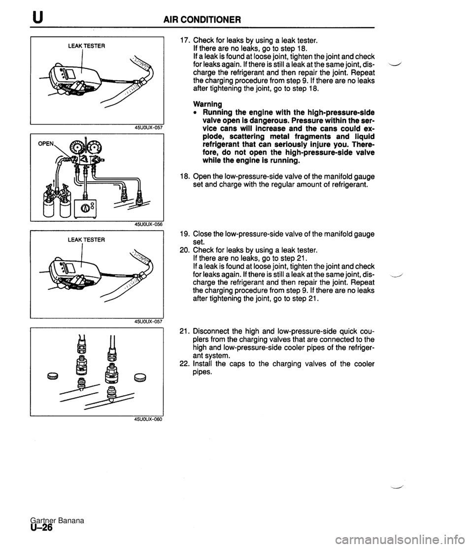
u AIR CONDITIONER LEAK TESTER I LEAK TESTER I 17. Check for leaks by using a leak tester. If there are no leaks, go to step 18. If a leak is found at loose joint, tighten the joint and check for leaks again. If there is still a leak at the same joint, dis- 4 charge the refrigerant and then repair the joint. Repeat the charging procedure from step 9. If there are no leaks after tightening the joint, go to step 18. Warning Running the engine with the high-pressure-side valve open is dangerous. Pressure within the ser- vice cans will increase and the cans could ex- plode, scattering metal fragments and liquid refrigerant that can seriously injure you. There- fore, do not open the high-pressure-side valve while the engine is running. 18. Open the low-pressure-side valve of the manifold gauge set and charge with the regular amount of refrigerant. 19. Close the low-pressure-side valve of the manifold gauge set. 20. Check for leaks by using a leak tester. If there are no leaks, go to step 21. If a leak is found at loose joint, tighten the joint and check for leaks again. If there is still a leak at the same joint, dis- charge the refrigerant and then repair the joint. Repeat the charging procedure from step 9. If there are no leaks after tightening the joint, go to step 21. 21. Disconnect the high and low-pressure-side quick cou- plers from the charging valves that are connected to the high and low-pressure-side cooler pipes of the refriger- ant system. 22. Install the caps to the charging valves of the cooler pipes. Gartner Banana
Page 1091 of 1708
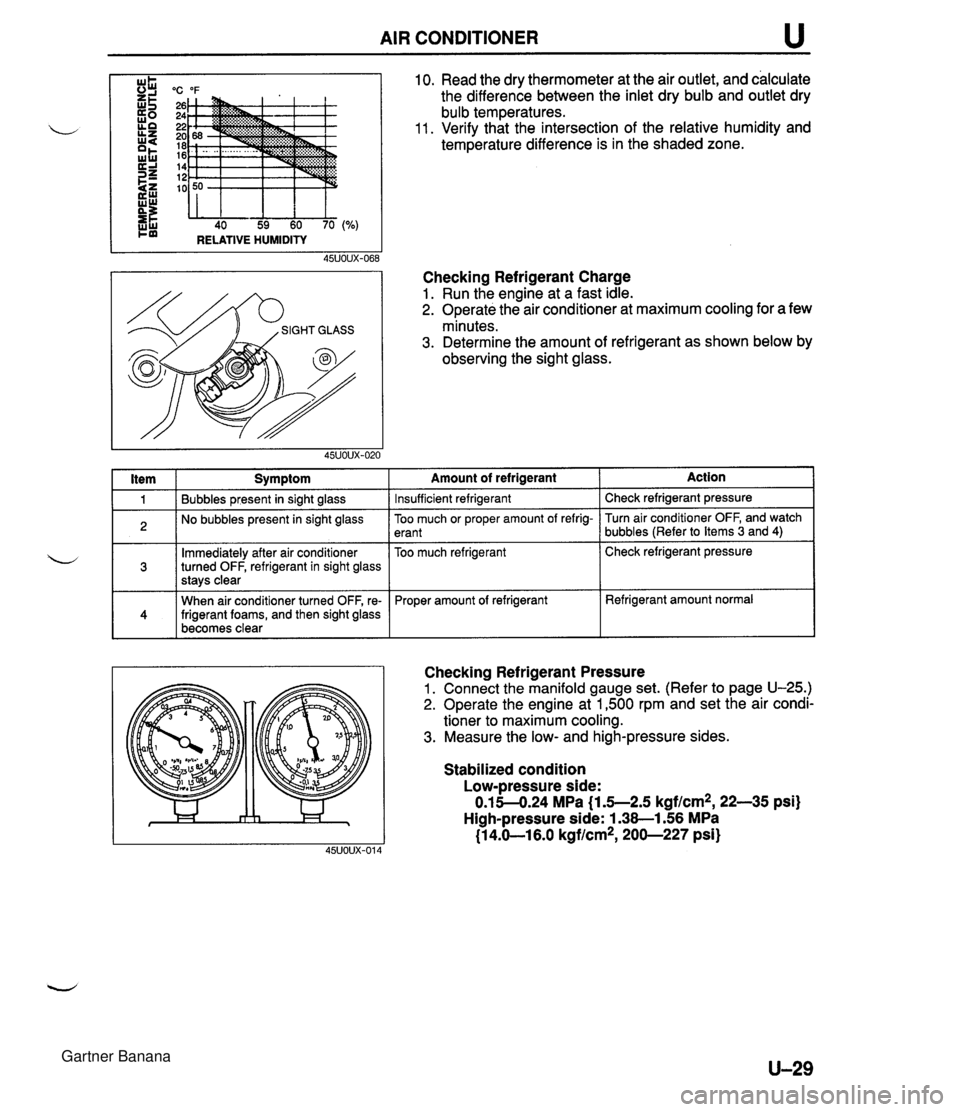
AIR CONDITIONER u "C "F 26 24 22 20 18 16 14 12 10 40 59 60 70 RELATIVE HUMIDITY I ltem I Symptom 10. Read the dry thermometer at the air outlet, and calculate the difference between the inlet dry bulb and outlet dry bulb temperatures. 11. Verify that the intersection of the relative humidity and temperature difference is in the shaded zone. Checking Refrigerant Charge 1. Run the engine at a fast idle. 2. Operate the air conditioner at maximum cooling for a few minutes. 3. Determine the amount of refrigerant as shown below by observing the sight glass. 1 Bubbles present in sight glass 2 No bubbles present in sight glass Immediately after air conditioner turned OFF, refrigerant in sight glass stavs clear 141 When air conditioner turned OFF, re- frigerant foams, and then sight glass becomes clear -- Amount of refrigerant Insufficient refrigerant Action Check refrigerant pressure -- Too much or proper amount of refrig- erant Too much refrigerant Checking Refrigerant Pressure 1. Connect the manifold gauge set. (Refer to page U-25.) 2. Operate the engine at 1,500 rpm and set the air condi- tioner to maximum cooling. 3. Measure the low- and high-pressure sides. Turn air conditioner OFF, and watch bubbles (Refer to Items 3 and 4) Check refrigerant pressure Proper amount of refrigerant Stabilized condition Low-pressure side: 0.15-4.24 MPa {I .5--2.5 kgf/cm2, 22-35 psi) High-pressure side: 1.38-1.56 MPa (1 4.61 6.0 kgflcm*, 200-227 psi) Refrigerant amount normal Gartner Banana
Page 1094 of 1708
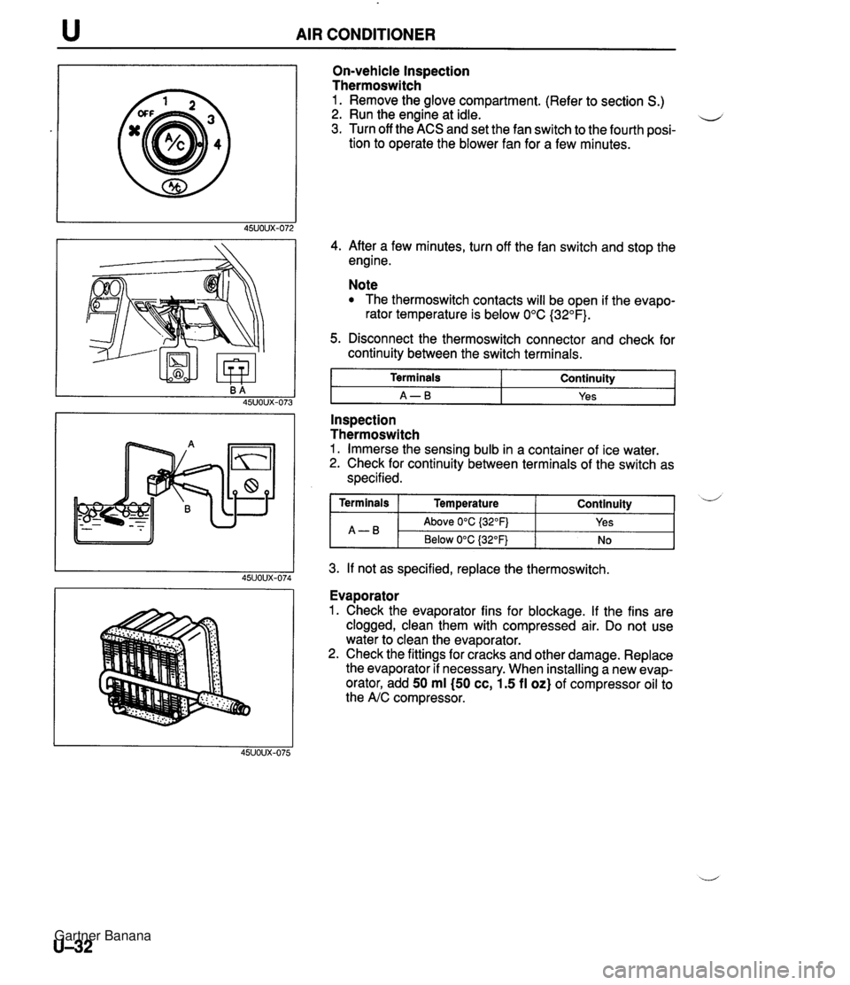
AIR CONDITIONER On-vehicle Inspection Thermoswitch 1. Remove the glove compartment. (Refer to section S.) 2. Run the engine at idle. u 3. Turn off the ACS and set the fan switch to the fourth posi- tion to operate the blower fan for a few minutes. 4. After a few minutes, turn off the fan switch and stop the engine. Note The thermoswitch contacts will be open if the evapo- rator temperature is below 0°C (32°F). 5. Disconnect the thermoswitch connector and check for continuity between the switch terminals. I Terminals I Continuity I I A-B I Yes I - -- Inspection Thermoswitch 1. Immerse the sensing bulb in a container of ice water. 2. Check for continuity between terminals of the switch as specified. 3. If not as specified, replace the thermoswitch. Continuity ( Terminals I Temperature A-B Evaporator 1. Check the evaporator fins for blockage. If the fins are clogged, clean them with compressed air. Do not use water to clean the evaporator. 2. Check the fittings for cracks and other damage. Replace the evaporator if necessary. When installing a new evap- orator, add 50 ml (50 cc, 1.5 fl oz) of compressor oil to the A/C compressor. d Above 0°C {32OFj Below 0°C (32°F) Yes No Gartner Banana
Page 1113 of 1708
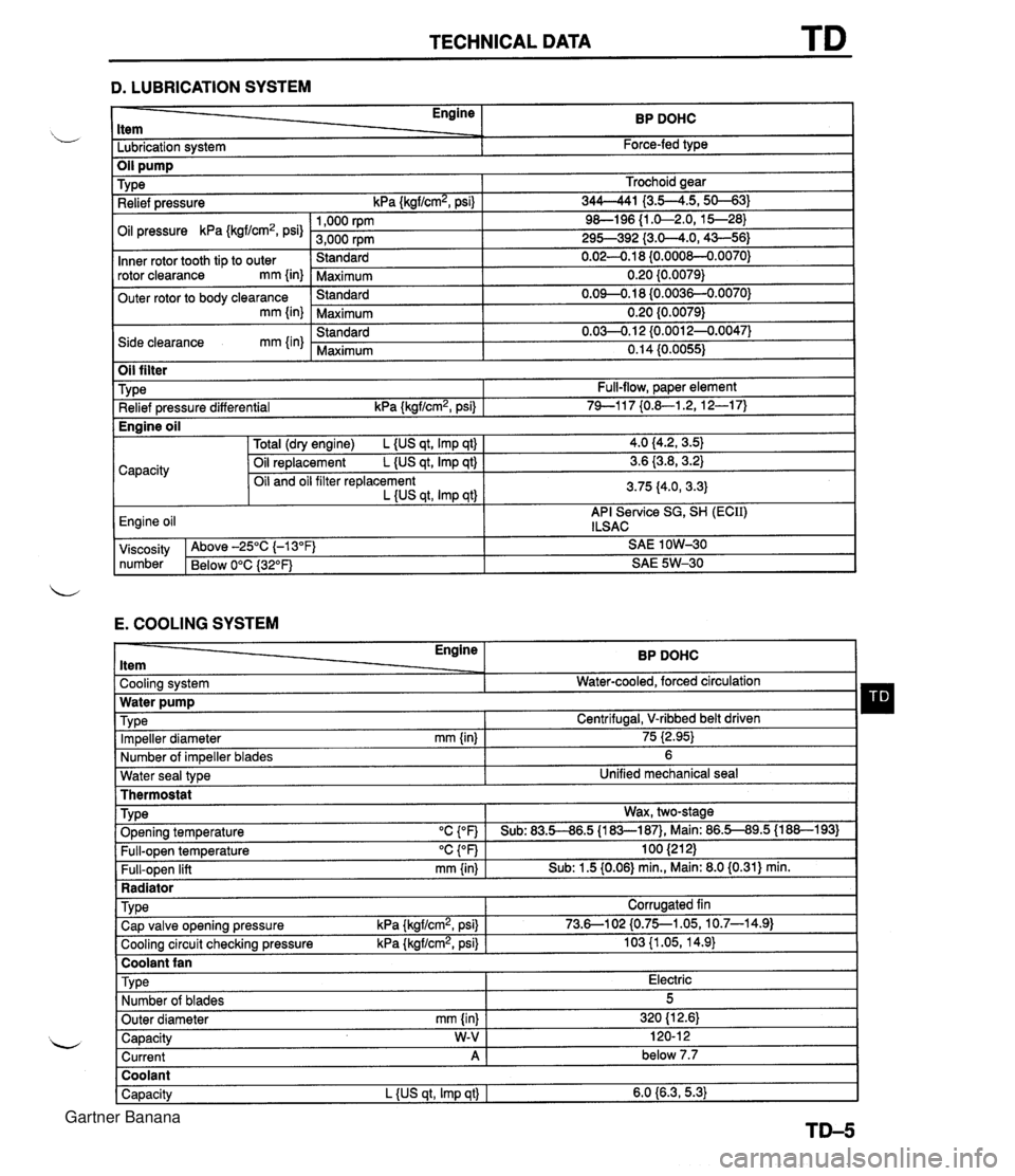
TECHNICAL DATA D. LUBRICATION SYSTEM - Engine ltem BP DOHC - -. Lubrication system Force-fed type E. COOLING SYSTEM Trochoid gear 344-41 I3.5--4.5,s-31 9&l96 {I .&2.0, 15--28) 295-392 {3.0-4.0,43-56) 0.02-0.1 8 {0.000&0.0070) 0.20 {0.0079) 0.09-0.18 (0.0036-0.0070) 0.20 {0.0079) 0.03-0.1 2 {0.0012-0.0047) 0.14 (0.0055) TY pe Relief pressure kPa {kgf/cm2, psi) Oil pressure kPa {kgf/cm2, psi) Inner rotor tooth tip to outer rotor clearance mm {in) Outer rotor to body clearance mm {in) Side clearance mm {in) Water seal type I Unified mechanical seal Thermostat 1,000 rpm 3,000 rpm Standard Maximum Standard Maximum Standard Maximum Oil filter Engine ltem - - Cooling system . . Impeller diameter mm {in) Number of impeller blades Type Relief pressure differential kPa {kgf/cm2, psi) BP DOHC Water-cooled, forced circulation - 75 i2.95) 6 Full-flow, paper element 74-1 17 {0.&1.2, 12-1 7) TY pe . ., . . . - Radiator I Water pump Wax, two-stage v. . . Full-open temperature "c {OF) Full-open lift mm {in) Engine oil TVD~ O~enina tem~erature "C con I Sub: 83.5-86.5 U83-187). Main: 86.5-89.5 (1 88-1 931 100 (21 2) Sub: 1.5 (0.06) min., Main: 8.0 (0.31) min. -. . - . . Cooling circuit checking pressure kPa {kgflcmz, psi) I 103 {I .05, 14.9) I Centrifugal, V-ribbed belt driven TY pe I Coolant fan I 4.0 (4.2, 3.5) 3.6 {3.8,3.2) 3.75 (4.0, 3.3) API Service SG, SH (ECII) ILSAC Capacity Corrugated fin viscosity Above -25°C (-1 3°F) SAE 1 OW-30 number Below 0°C {3Z°F) SAE 5W-30 Total (dry engine) L {US qt, Imp qt) Oil replacement L {US qt, Imp qt) Oil and oil filter replacement L {US qt, Imp qtl Cap valve o~enina pressure kPa {krrf/cm2, psi} 1 73.6--102 {0.75--1.05, 10.7-14.91 Capacity W-V I 120-1 2 Current A 1 below 7.7 Engine oil Type Number of blades Outer diameter mm {in) Coolant Capacity L {US qt, Imp qt) I 6.0 {6.3,5.3) Electric 5 320 (1 2.61 Gartner Banana
Page 1124 of 1708
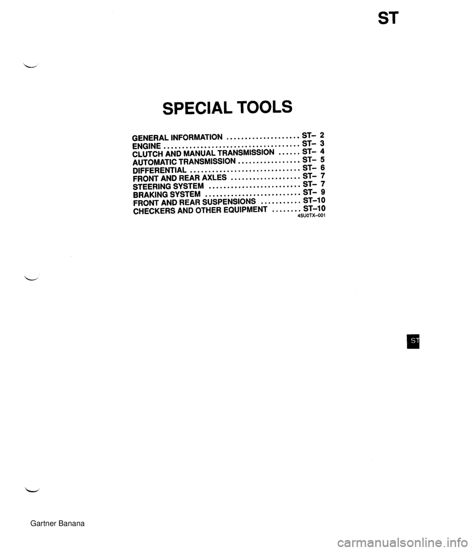
SPECIAL TOOLS .................... GENERAL INFORMATION ST- 2 ..................................... ENGINE ST- 3 CLUTCH AND MANUAL TRANSMISSION ...... ST- 4 ................. AUTOMATIC TRANSMISSION ST- 5 .............................. DIFFERENTIAL ST- 6 ................... FRONT AND REAR AXLES ST- 7 ......................... STEERING SYSTEM ST- 7 .......................... BRAKING SYSTEM ST- 9 ........... FRONT AND REAR SUSPENSIONS ST-1 0 CHECKERS AND OTHER EQUIPMENT ........ ST-10 4SUOTX-001 Gartner Banana
Page 1133 of 1708
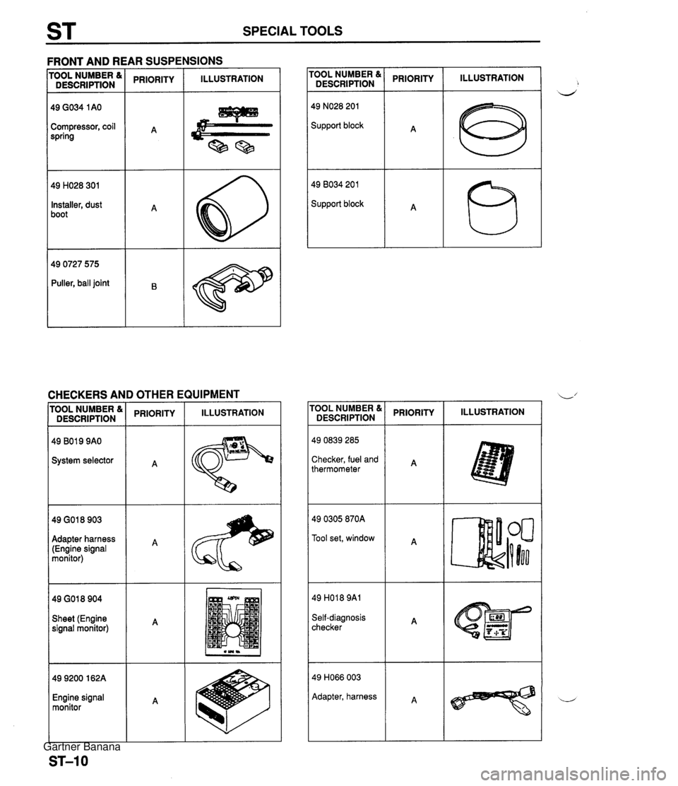
ST SPECIAL TOOLS \R SUSPENSIONS - - - FRONT AND RI EEFZ rooL NUMBER & ( PRIORITY I ILLUSTRATION DESCRIPTION PRIORITY ILLUSTRATION 49 NO28 201 Support block Compressor, coil spring 49 8034 201 Support block Installer, dust boot 49 0727 575 Puller, ball joint CHECKERS AND OTHER EQUIPMENT I I rooL NUMBER & DESCRIPTION PRIORITY ILLUSTRATION PRIORITY I ILLUSTRATION System selector Checker, fuel and thermometer 49 0305 870A Tool set, window Adapter harness (Engine signal monitor) Sheet (Engine signal monitor) Self-diagnosis checker 49 H066 003 Adapter, harness Engine signal monitor Gartner Banana
Page 1698 of 1708
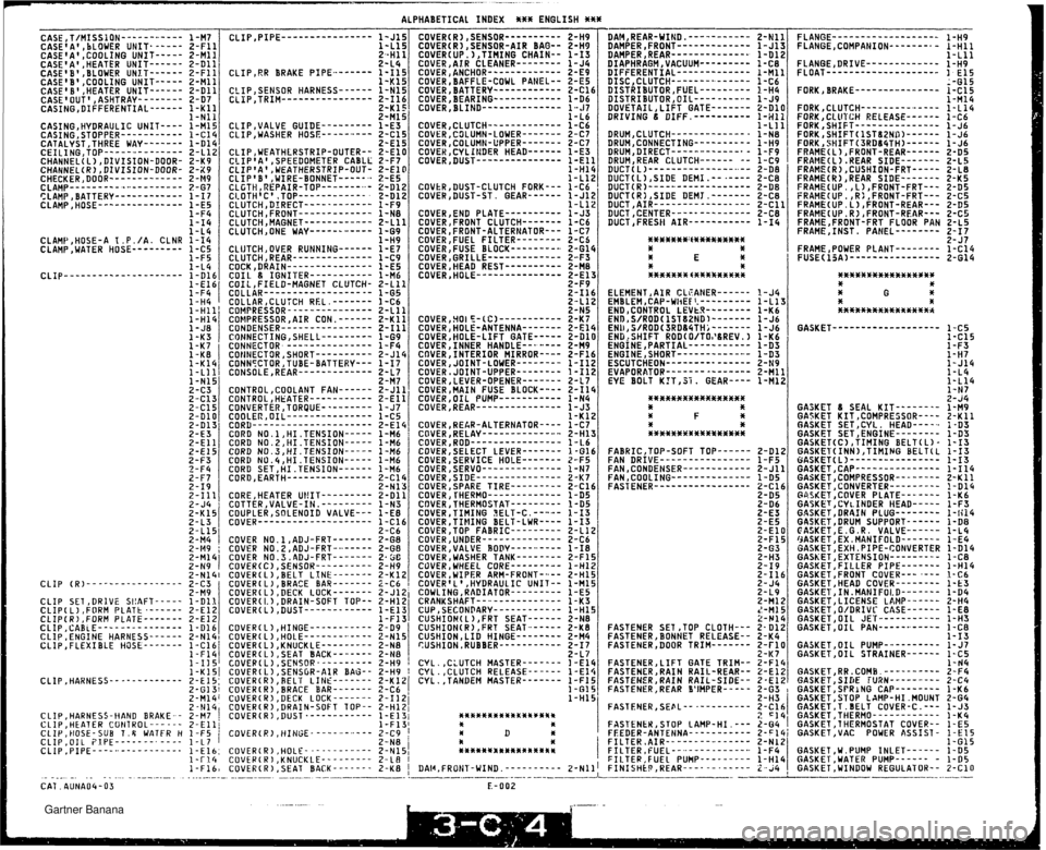
ALPHABETICAL INDEX *%* ENGLISH *** CASE,T/MISSlON------------ CASE'A' , LLOWER UNIT- ----- CASE'A',COOLING UNIT----- CASE'A1 ,HEATER UNIT------ CASEIB' ,BLOWER UNLT------ CASE'B' ,COOLING UNIT----- CASE'B9,HEATER UNIT------ CASE'OUT',ASHTRAY-------- CASING,DIFFERENTIAL------ CASING,HYDRAULIC UNIT---- CASING,STOPPER----------- CATALYST ,THREE WAY------- CEILING,TOP-----.--------- CHANNEL( L) DIVISION-DOOR- CHANNEL(R)lDIVISION-DOOR- CHECKER,DOOR------------- CLAMP---------.-..--------- CLAMP,BATTERY------------ CLAMP,HOSE--------------- 1-L11 DRUM,CLUTCH-------------- 1-N8 DRUM,CONNECTING---------- 1 -H9 DRUM,DIRECT------------.- 1-F9 DRUMIREAR CLUTCH------ -- 1-C9 DUCT(L)---------------..-- 2-DB DUCT(L1 ,SIDE DEMI .-- .---- DUCT(R)----..------------- 2-C8 2-DB DUCT(R1,SIDE DEMT,------- DUCT,AIR- ---- ------------ 2-C8 DUCT,CENTER-------------- 2-Cll 2-C8 DUCTIFRESII AIR----------- 1-14 CLIP,WEATHLRSTRIP-OUTER-- 2-El1 CLIPtA',SPEEDOMETER CABLL 2-F7 CLIPIA',WEATHERSTRIP-OUT- 2-El1 CLIPIB',WIRE-BONNET------ 2-E5 CLGTH,REPAIR-TOP-------..- 2-Dli CLAMt3,HOSE-A 1 .P. /A. CLNR CLAMP,WATER HOSE--------- ELEMENTIAIR CLEANER------ 1-J4 EMBLEM,CAP-WIiE€I.--------- 1-Ll;? END,CONTROL LEVtR-------- 1 -K6 ENDlS/ROD<1ST82ND)------- 1-J6 ENl)rS/ROD(3RDB4TH;------- 1-J6 ENG:SHIFf ROD(O/TOI'&REV.) 1-K6 ENGINE,PARTIAL----------- ENGINE,SHORT------------.- 1-D3 ESCUTCHEON--------------- 1-D3 EVAPORATOR--------------- 2-ti9 2-Mll EYE BOLT K?T,31. GEAR---- 1-M12 2-116 2-L12 2-N5 COVER,5OIE-CC1----------- 2-Ki COVER,HOLE-ANTENNA------- 2-El4 COVER,HOLE-LIFT GATE----- 2-Dl0 COVER,INNER HANDLE----.--- 2-M9 COVER,INTERIOR MIRRORm--- 2-F16 COVER,JOINT-LOWER-------- 1-112 COVER,JOINT-UPPER-------- 1-112 COVER,LEVER-OPENER------- 2-L7 COVER,MAIN FUSE BLOCK---- 2- I1 4 COVER,OIL PUMP----------- COVER,REAR--------------- 1-N4 1-J3 1-K12 COVEK,RE&R-ALTERNATOR---- 1-C7 CQVER,RELAy------------..- 2-H1! COVER,ROD---------------- 1-1.6 COVER,SELECT LEVER------- 1-616 COVERISERVICE HOLE------- Z-F5 COVER,SERVO-------------- COVER,SIDE--------------- 1-N7 2-K7 COVERISPARE TIRE--------- 2-Cl6 COVER,l'HERHO------------- 1-D5 CQVER,THERMOSTAT--------- 1-D5 COVER,TIMING EELT-C. ----- 1-13 GASKET------------------- 1-C5 1-C15 1 -F3 1-H7 1-J14 1-L4 1 - L 14 1-N7 2- ~4 GASKET 8 SEAL KIT-------- 1-M9 GASKET KIT,COMPRESSOR---- 2-K11 GASKET SET ,CYL HEAD----- i -D3 GASKET SETIENGINE-------- 1-DY GASKET(C1 ,TIMING BELTCL) - 1-13 GASKEl'(INN),TIHIHG BELTCL 1-13 BASKET(L)---------------- GASKET,CAP--------------- 1-13 1-114 GASKETICONPRESSOR-------- 2-K11 GASKET,CONVERTER--------- !-Dl4 G0.SKET ,COVER PLATE------- 1-K6 GASKET,CYl.INDER WEAD----- 1-F3 GASKET,DRAIN PLUG-------- 1-li14 GASKETIDRUM SUPPORT- ----- 1 - D8 CASKET.E.G.R. VALVE------ 1-L4 CORD NO.1,HI.TENSION----- 1 -M6 CORD NO.2.HI.TENSION----- 1 -M6 CORD NO.~;HI.TENSION----- 1 -M6 CORD NU.4,HI.TENSION----- 1 -M6 CORD SET,HI.TENSION------ 1 -M6 CORa,EARTH--------------- 2-c14 2-Nl:! CORE,HEATER Ub!IT--------- 2-Dl1 COTTER,VALVE-IN.--------- 1 -N3 COUPLERISOLENOID VALVE--- 1-E0 COVER-------------------- l-Cl6 2-C6 COVER NO.l,ADJ-FRT------- 2-66 COVER NO.2,ADJ-FRT-a+----- 2-60 COVER N0.3.ADJ-FRT------- 2. SC COVER(C),SENSOK---------- 2-H9 COVER(L),BELT LINE------- 2-Kli COVER(L).BRACE BAR------- 2-C6 COVER,UNDER-------------- 2-C6 COVER,VALVE BODY--------- 1-10 COVER,WASHER TANK-------- 2-F1E COVER,WHEEL CORE--------- 1-Hli COVER, WIPER ARM-FRONT--- - 2-H15 COVER'L1,HYDRAULIC UNIT-- 1-Ml5 COWLING,RADIATOR--------- CRANKSHAFT--.. -- ------ ---- 1-E5 1 -K3 CUPISECONDARY------------ 1-H15 CUSHION(L),FRT SEAT------ 2-N8 CUSHIOW(R),FRT SEAT------ 2-K8 CUSHION,LID HINGE-------- 2-H4 CUSHION.RUBBER----------- 2-17 2-Ll CYL.,CLUTCH MASTER------- I -El4 CYL.,CLUTCH RELEASE------ 1-El4 CYL,,TAHDEM MASTER------- 1-F15 1-61 5 1-H15 /~ASKET;EX.MANIFOLD------- 1-E4 GASKET,EXH.PIPE-CONVERTER 1-Dl4 GASKET,EXTENSION--------- 1-C8 GASKET,FILLER PIPE------- 1-H14 GASKET ,FRONT COVER--- .--- I-C6 GASKET,HEAD COVER-------- 1-fi3 GASKET,IN.MANIFOl.D------- 1-D4 GASKET.LICENSE LAMP------ 2-H4 COVER( L) ;DECK LOCK------- 2- Jli COVER(I.),DRAIN-SOFT TOP-- 2-Hli COVER(L),DUST------------ 1-El2 1-Fl? COVER(L),HINGE----------- 2-D9 COVER( L) ,HOLE----------- - 2-Nl! COVER(L),KNUCKLE--------- 2-NB COVER(L).SEAT BACK------- 2-N8 - ... CLIP SET,DRlVE SI!AFT----- 1-DlI CLIP(L1 ,FORM PLATt .------ 2-El2 CLIP(R),FORM PLATE------- CLIP,CABiE--------------- 2-El2 1-Dl6 CLIP ,ENGINE HARNESS------ 2-N141 CLIP,FLEXIBLE Hi3SE------- 1-C16' l-~ld I-Ml5 2-1314 FASTENER SET ,TOP CLOTH--- 2- Dl2 FASTENER,BONNET RELEASE-- 2-KG FASTENER,DOOR TRIM------- 2-rl0 2-#7 GASKET,OIL PUMP---------- 1- J7 GASKET ,OIL STRAINER-- ---- 1-C5 1-rJ4 GASKET.RR.COH0.---------- 2-F4 1-1jsl CQv~~(~);S~~so~-l-------- 2-H9 I I-K~SI COVER( L) ,SENSOR-AIR BAG-- 2-H9 CLIP,HAHNESS------------- 2-E15: COVER(R),REL'I LINE------- FKl4 2-G13! COVER(R),BRACE BAR------- 2-C6 , 2-M14' CUVER(W),DECK LOCK------- 2-1121 2-N14( COVERIR) ,DRAIN-SOFT TOP-- 2-HIZi CLlP,HARNESS-HAND BRAKE-- 2-M7 I COVERCR) ,DUST.----------- 1-E13i CLlP,HEATER COtITKOL--- - -- 2-Elli 1-F131 CLIP, HOSE- SUB T.8 VATFR H 1 -F5 i COVER(R) ,HINGE- ---------- 2-C9 ! CLIP,OIL FJPE-------. ---- 1-L7 I CLIP ,PIPE--- -..- ---------. 2-N8 j I-El6: COVER(R),HOLE------------ Z-N1S1 x-~I(+ COVER(RI,KNUCKLE--------- 2-18 I 1-Fl6, COVER(R) ,SEAT BACK------- 2-K8 I FASTEHERILIFT GATE TRIM-- 2-F14 FASTENERBRAIN RAIL-REAR-- %-Eli FASTEHER; RAIN FASTENER. REAR 1 SIDE TUXN- - .SPRANG CAP- FASTEYER,SEEL------------ 1- J3 1-K4 FASTENER, STOP LAMP-HI . --- II D f FEEDER-ANTENNA- - - - - -- - - - - 2-F14j GASKET~VAC POWER ASSIST- !-El5 I )t s FILTER ,AIR--------..------ 2 - N 12 1-G15 FILTER, FUEL- - ..- - - - - - ----.. ~%*t*~x*rfi**tf%%w 1-F4 1 SASK6T.W.PUMP INLET------ 1-D5 I FII.TEP,FUEL PUMP--------- 1-H14 GASKET,WATER PUMP------ - 1-05 IlAl~,FRONT-WIND.---------- 2-~111 FINISHEPIWEAR------.----- 2-i4 GASKET,WINDOW REGULATOR-- 2-C10 . . . . . . . -. . . . . . -- .. - -- ------- L.- -.- --- -.-- CAT. AUNA04-03 F.-002 Gartner Banana