1994 MAZDA MX-5 fuel
[x] Cancel search: fuelPage 296 of 1708

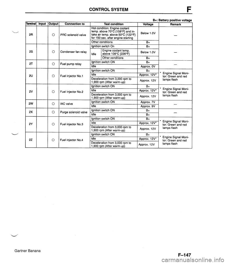
CONTROL SYSTEM F Connection to I Test condition I Hot condition: Enaine coolant Input - temp. above 70°C (1 58"~) and in- PRC solenoid valve take air temp. above 50°C (122°F) for 150 sec. after enaine startina Output 0 0 0 0 0 0 0 0 0 " " Other conditions lanition switch On - Condenser fan relay Engine coolant temp. Idle above 108°C 1226°F) I I Other conditions ' I lgnition switch ON Fuel pump relay ldle I I lanition switch ON Fuel injector No.1 1,900 rpm (After warm-UD) I lgnition switch ON Fuel injector No.2 ldle Deceleration from 3,000 rprn to 1,900 rpm (After warm-up) lgnition switch ON IAC valve ldle lgnition switch ON Purge solenoid valve ldle Fuel injector No.3 lgnition switch ON ldle Deceleration from 3,000 rpm to 1,900 rpm (After warm-up) lanition switch ON Fuel injector No.4 Idle Deceleration from 3,000 rpm to 1,900 rpm (After warm-up) Below 1 .OV -1 Below 1 .OV B+ - Approx. OV Engine Signal Moni- * Engine Signal Moni- tor: Green and red Approx. 12V I lamps flash B+: Battery positive voltage Voltage I Remark * Engine Signal Moni- tor: Green and red Engine Signal Moni- Gartner Banana
Page 300 of 1708

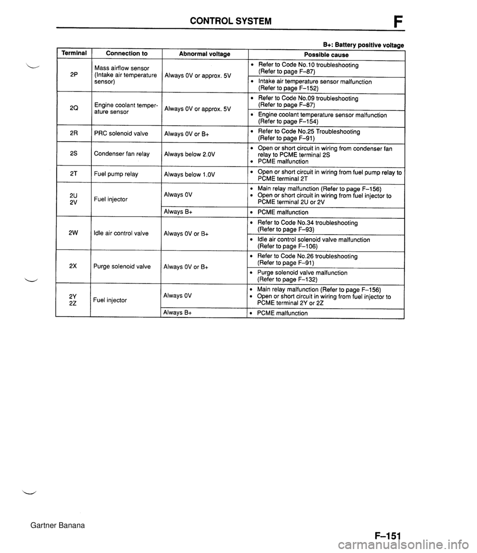
CONTROL SYSTEM B+: Battery positive voltage Terminal Connection to Abnormal voltaae Possible cause Mass airflow sensor (Intake air temperature sensor) Refer to Code No.10 troubleshooting (Refer to page F-87) Always OV or approx. 5V Intake air temperature sensor malfunction (Refer to page F-152) Refer to Code No.09 troubleshooting (Refer to page F-87) Engine coolant temper- ature sensor Always OV or approx. 5V r Engine coolant temperature sensor malfunction (Refer to page F-154) Refer to Code No.25 Troubleshooting (Refer to page F-91) Always OV or B+ PRC solenoid valve r Open or short circuit in wiring from condenser fan relay to PCME terminal 25 PCME malfunction Open or short circuit in wiring from fuel pump relay to PCME terminal 2T Condenser fan relay Always below 2.OV Fuel pump relay Always below 1 .OV Main relay malfunction (Refer to page F-156) r Open or short circuit in wiring from fuel injector to PCME terminal 2U or 2V Always OV Fuel injector ldle air control valve Purge solenoid valve Always B+ Always OV or B+ Always OV or B+ PCME malfunction r Refer to Code No.34 troubleshooting (Refer to page F-93) ldle air control solenoid valve malfunction (Refer to page F-I 06) r Refer to Code No.26 troubleshooting (Refer to page F-91) r Purge solenoid valve malfunction (Refer to pane F-132) -- Fuel injector Always OV Main relay malfunction (Refer to page F-156) Open or short circuit in wiring from fuel injector to PCME terminal 2Y or 22 Always B+ PCME malfunction Gartner Banana
Page 302 of 1708

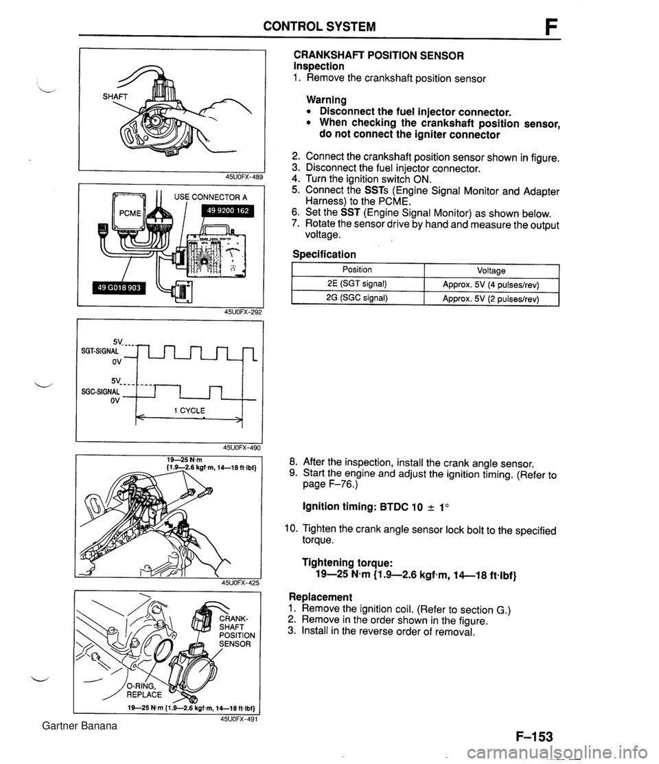
CONTROL SYSTEM 1 1 USE CONNECTOR A CRANKSHAFT POSITION SENSOR Inspection 1. Remove the crankshaft position sensor 5v- - - - SGGSIGNAL ov Warning Disconnect the fuel injector connector. When checking the crankshaft position sensor, do not connect the igniter connector - - - - I 1 CYCLE < > 2. Connect the crankshaft position sensor shown in figure. 3. Disconnect the fuel injector connector. 4. Turn the ignition switch ON. 5. Connect the SSTs (Engine Signal Monitor and Adapter Harness) to the PCME. 6. Set the SST (Engine Signal Monitor) as shown below. 7. Rotate the sensor drive by hand and measure the output voltage. Specification I 1 - Position - ~oltaael 8. After the inspection, install the crank angle sensor. 9. Start the engine and adjust the ignition timing. (Refer to page F-76.) 2E (SGT signal) 2G (SGC signal) Ignition timing: BTDC 10 2 1" Approx. 5V (4 pulseslrev) Approx. 5V (2 pulseslrev) 10. Tighten the crank angle sensor lock bolt to the specified torque. Tightening torque: 19-25 N-m (1 .+2.6 kgfem, 14-1 8 ftelbf} Replacement 1. Remove the ignition coil. (Refer to section G.) 2. Remove in the order shown in the figure. 3. Install in the reverse order of removal. Gartner Banana
Page 305 of 1708

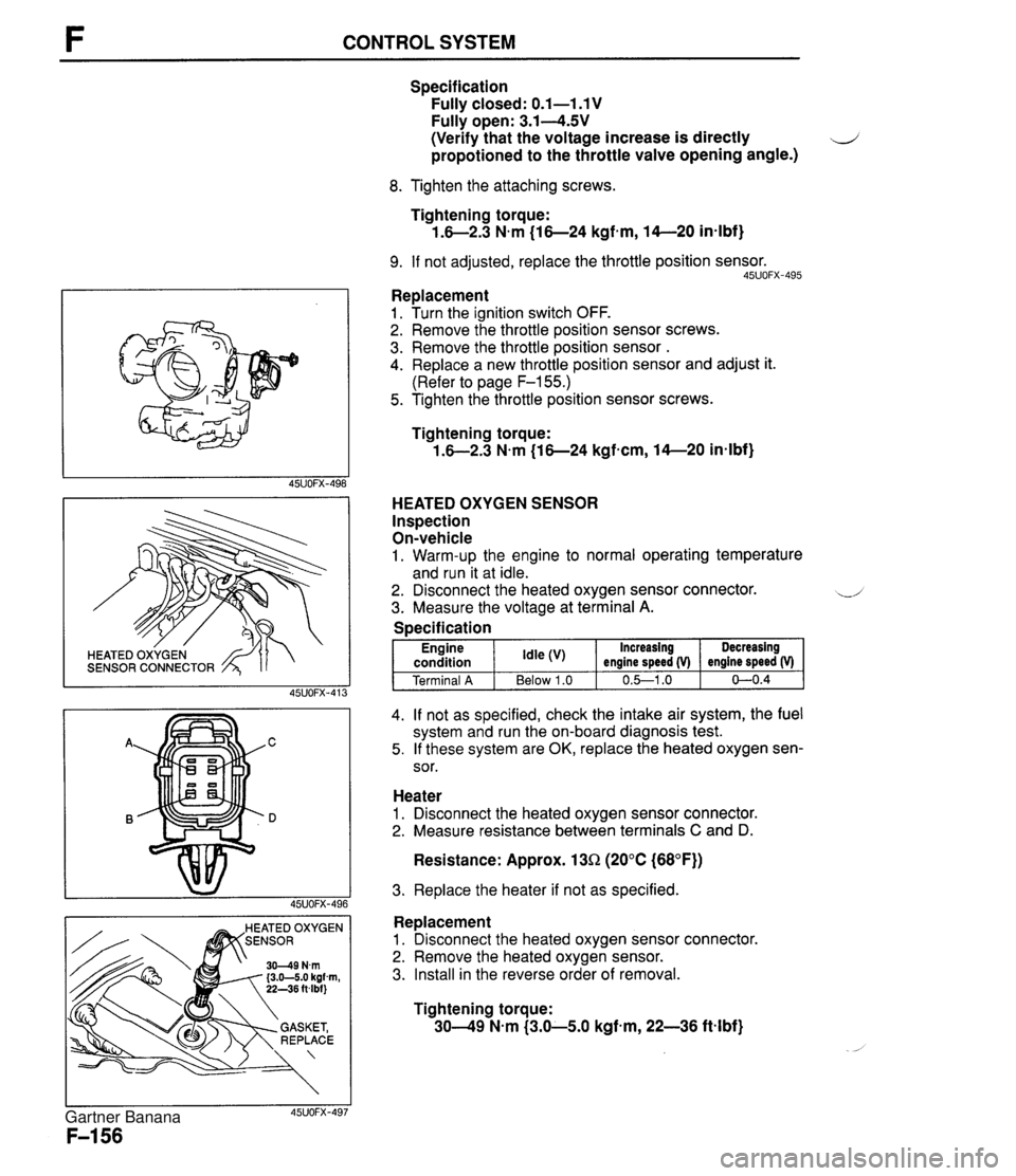
CONTROL SYSTEM SENSOR CONNECTOR EATED OXYGEN Specification Fully closed: 0.1-1.1 V Fully open: 3.14.5V (Verify that the voltage increase is directly d propotioned to the throttle valve opening angle.) 8. Tighten the attaching screws. Tightening torque: 1.6-2.3 N.m (16-24 kgfmm, 14-20 in-lbf} 9. If not adjusted, replace the throttle position sensor. 45UOFX-495 Replacement 1. Turn the ignition switch OFF. 2. Remove the throttle position sensor screws. 3. Remove the throttle position sensor . 4. Replace a new throttle position sensor and adjust it. (Refer to page F-155.) 5. Tighten the throttle position sensor screws. Tightening torque: 1.6-2.3 N.m (16-24 kgf-cm, 14-20 in-lbf} HEATED OXYGEN SENSOR Inspection On-vehicle 1. Warm-up the engine to normal operating temperature and run it at idle. 2. Disconnect the heated oxygen sensor connector. -.-' 3. Measure the voltage at terminal A. 4. If not as specified, check the intake air system, the fuel system and run the on-board diagnosis test. 5. If these system are OK, replace the heated oxygen sen- sor. Specification Heater 1. Disconnect the heated oxygen sensor connector. 2. Measure resistance between terminals C and D. Resistance: Approx. 13R (20°C (68°F)) Engine condition Terminal A 3. Replace the heater if not as specified. Increasing engine speed (V) 0.&1 .O Idle Below 1.0 Replacement 1. Disconnect the heated oxygen sensor connector. 2. Remove the heated oxygen sensor. 3. Install in the reverse order of removal. Decreasing engine speed (V) 0-0.4 Tightening torque: 3049 N-m (3.0-5.0 kgf-m, 22-36 ftlbf) Gartner Banana
Page 736 of 1708

OUTLINE OUTLINE SPECIFICATIONS Front Suspension - Transmission item (Stabilizer Specifications MT I AT - I Susoension tvoe I . , . , I . , Shock absorber Cylindrical double acting, low-pressure-gas charged I Double-wishbone TY pe Torsion bar Coil spring I - Diameter mm linl I 20.0 10.79) Identification mark color 19.0 (0.75) White Wire diameter mm (in) Coil inner diameter mm {in) I Blue Free length mm {in) Coil number 11 .O (0.43) 83 i3.27) 11 .O (0.43) 83 (3.27) 292.5 (1 1 32) 6.32 3 +. 3 (0.12 + 0.12) 0°18' + 18' Total toe-in I - I 35UORX-001 Rear Suspension 302.0 (1 1.89) 6.32 mm {in) degree Total toe-in (per side) 1 degree Front wheel alignment (Unladedt1) 0°09' +. 09' Caster anglee3 4"26' +. 45' Kingpin angle 11 "20' Maximum steering angle Transmission Specifications MT I AT Item Differential - Suspension type Inner Outer "TORSEN" LSD 1 Standard Double-wishbone Coil springs 370 23' a 2" 32" 32' -t 2" Camber anglee2 Torsion bar 12.0 (0.47) 1 11.0 (0.43) 1 11 .O (0.43) Cylindrical double acting, low-pressure-gas charged - Stabilizer Identification mark color Wire diameter mm {in) 0°24' + 45' Type Diameter mm {in) I Coil number I 7.68 I 7.96 I Shock absorber Yellow 10.1 {0.40} Coil inner diameter mm {in) Free length mm {in) Green 10.2 {0.40) 35UORX-002 *I Fuel tank full; radiator coolant and engine oil at specified levels; spare tire, jack, and tools in designated positions. '2 Difference between left and right must not exceed I O. '3 Difference between left and right must not exceed 1'30'. "TORSEN" is a registered trademark of ZEXEL-GLEASON USA.INC 83 I3.27) 348.5 j13.72) Rear wheel alignment (Unladed*') 83 (3.27) 356.5 (1 4.04) Total toe-in Total toe-in (per side) mm (in) degree degree 3 -c 3 (0.12 + 0.121 0°18' + 18' 0°09' + 09' Camber angle*2 -0°43' 2 30' Gartner Banana
Page 738 of 1708

WHEEL ALIGNMENT WHEEL ALIGNMENT FRONT WHEEL ALIGNMENT Specifications (Unladed*l) PRE-INSPECTION 1. Check the tire inflations, and adjust to the recommended d pressure if necessary. 2. lnspect the front wheel bearing play and correct if neces- sary. 3. lnspect the wheel and tire runouts. 4. Inspect the ball joints and steering linkage for excessive looseness. 5. The vehicle must be on level ground and carry no lug- gage or passengers. 6. Measure the height from the center of the wheel to the fender brim. The difference between left and right mea- surement must not exceed 10mm (0.39 in), and the rear measurement must be larger then the front measure- ment by 10-30mm (0.4--1.1 in). Caution The proper caster and camber angle vary depend- ing on the vehicle height. Refer to the following and to page R-9 for the specifications. Inspection and adjustment of wheel alignment must be done with the vehicle unladed*'. . . I Y -- t~otal toe-in l~er side) I 1 dearee 0'09' + 09' I Total toe-in 3 2 3 I0.12 2 0.12) 0'1 8' 2 18' mm (in) dearee Maximum steering angle U - Inner Outer 11 '20' -0°20' 2 45' 0'03' ? 45' 0'24' 2 45' 0°44' -+ 45' 1'02' -+ 45' 5'1 6' ? 45' 5O02' -+ 45' 4O49' 2 45' 4'35' -+ 45' 4'21 ' -+ 45' I Kingpin angle 37"23' -+ 2" 32O32' 2 2" '1 Fuel tank full; radiator coolant and engine oil at specified levels; spare tire, jack, and tools in designated positions. OSUORX-009 ** Difference between left and right must not exceed lo. '3 Difference between left and right must not exeed 1'30'. 328-337 {I 2.9-1 3.3) 338-347 {I 3.3-1 3.7) 340-357 I13.7-14.1) 358-367 {I 4.1-14.4) 36&377 {I 4.4--14.8) 328-337 {I 2.9--13.3) 338-347 {I 3.3-1 3.7) 348-357 113.7-14.1) 358-367 {I 4.1-14.4) 368-377 {I 4.4--14.8) Camber angleg2 Caster angle*3 Height from center Of wheel to fender brim mm {in) Height from center Of wheel to fender brim mm (in) Gartner Banana
Page 741 of 1708

WHEEL ALIGNMENT REAR WHEEL ALIGNMENT Specifications (Unladed*) I Item I Specifications I L *' Fuel tank full; radiator coolant and engine oil at specified levels; spare tire, jack, and tools in designated positions. 05Uo~x-01~ *2 Difference between the leff and right must be exeed lo. 3 + 3 i0.12 * 0.12) 0'18' k18' 0'09' 2 09' -1 "08' +. 30' Total toe-in Total toe-in (per side) Camber angle'' LEFT WHEEL - mm {in) degree degree INCREASE I 1 346-355 (1 3.6-1 4.0) Height from center of wheel to fender brim'2 mm Iin) RIGHT WHEEL C INCREASE 356-3135 {14.0-14.4) 366-375 {I 4.4--14.8) 376-385 {I 4.8-1 5.2) 386--395 {I 5.2-1 5.6) LEFT WHEEL -C -0°54' r 30' -0'43' 2 30' -0°35' r 30' -0'30' +. 30' Toe-in Toe-in is adjusted by turning the front and/or rear adjust- ing cam bolts at the lower arm. Caution Adjust the toe-in before adjusting the camber. 1. Loosen the front and/or rear cam nuts. 2. Turn the front and/or rear adjusting cam bolts to provide the correct toe-in. I Counter- Counter- Decrease Clockwise Clockwise clockwise clockwise Toe-in Note Turning the front cam one graduation changes the toe-in about 2.8mm (0.11 in} and the camber about 15'. Turning the rear cam one graduation changes the toe-in about 2.8mm I0.11 in} and the camber about 6'. 3. 'Adjust the camber. Left wheel Camber Camber is adjusted by turning the front and rear cams at the lower arm. Right wheel Caution Adjust the camber after adjusting the toe-in. Front cam I Rear cam I Front cam I Rear cam 1. Loosen the front and rear cam nuts. 2. Turn the front and rear adjusting cam bolts the same amount in the opposite direction to provide the correct camber angle. Gartner Banana
Page 759 of 1708

Before beginning any service procedure. refer to section T of this manual for air bag system service warnings and audio antitheft system alarm conditions . BODY INDEX ............................. S- 2 HOOD ............................. S- 5 COMPONENTS ................... S- 5 DOOR ............................. S- 7 COMPONENTS ................... S- 7 WINDOW REGULATOR. GLASS. AND GUIDE ....................... S- 9 COMPONENTS ................... S- 9 ......... DOOR LOCK AND OPENER S-15 ................... COMPONENTS S-15 TRUNK LID ........................ S-16 COMPONENTS ................... S-16 .... TRUNK LID LOCK AND OPENER S-18 COMPONENTS ................... S-18 ......... POWER WINDOW SYSTEM S-19 .............. STRUCTURAL VIEW S-19 TROUBLESHOOTING ............. S-20 ........ b POWER WINDOW SWITCH S-22 ... POWER WINDOW REGULATOR S-22 ......... FUEL-FILLER LID OPENER S-23 COMPONENTS ................... S-23 FRONT BUMPER ................... S-24 COMPONENTS ................... S-24 REAR BUMPER .................... S-25 COMPONENTS ................... S-25 ........... MOLDING AND GARNISH S-27 COMPONENTS ................... S-27 OUTSIDE MIRROR ................. S-30 STRUCTURAL VIEW .............. S-30 ............. TROUBLESHOOTING S-31 POWER OUTSIDE MIRROR ....... S-33 POWER OUTSIDE MIRROR SWITCH ........................ S-33 COMPONENTS ................... S-34 WINDSHIELD WIPER AND WASHER . S-35 TROUBLESHOOTING ............. S-35 WIPER MOTOR .................. S-38 ................ WASHER MOTOR S-38 FRONT WIPER AND WASHER ........................ SWITCH S-38 ................... COMPONENTS S39 WINDSHIELD ...................... S-44 PREPARATION ................... S-44 ................... COMPONENTS S-44 REAR WINDOW GLASS ......... (DETACHABLE HARDTOP) S-48 PREPARATION ................... S48 ................... COMPONENTS S48 REAR WINDOW .............. (CONVERTIBLE TOP) S-52 ................... COMPONENTS S-52 ....... DASHBOARD AND CONSOLE S-56 ................... COMPONENTS S56 TRIM .............................. S-59 COMPONENTS ................... S-59 ................. FLOOR COVERING S-62 ................... COMPONENTS -21 SEAT BELT ........................ S-63 COMPONENTS ................... S-63 ...................... SEAT BELT S-64 ................ BUCKLE SWITCH S-64 SEAT .............................. S-65 ................... COMPONENTS S-65 ................ CONVERTIBLE TOP S-67 PREPARATION ................... S-67 ................... COMPONENTS S-67 ........... DETACHABLE HARDTOP S-81 COMPONENTS ................... S-81 BRACE BAR ....................... S-84 ................... COMPONENTS S-84 ......... UNDERBODY DIMENSIONS S-85 PROJECTED DIMENSIONS ........ S-85 ..... STRAIGHT-LINE DIMENSIONS S-87 45uoSx-001 Gartner Banana