Page 239 of 1708

F ON-BOARD DIAGNOSIS SYSTEM CODE No. 17 (HEATED OXYGEN SENSOR: INVERSION) I Circuit Diagram INSPECTION Warm up engine and run it at 2,500-3,000 rpm for 3 min. HEATED OXYGEN SENSOR ACTION Does monitor lamp of Self-Diagnosis Checker illu- minate at idle? Are spark plugs clean? Is heated oxygen sensor voltage OK? * page F-156 Is same Code No. present after performing after repair procedure? ESI= page F-90 Is there continuity between heated oxygen sensor and PCME terminal 2N? Is PCME terminal 2N voltage OK? * page F-146 PCME Yes No Yes No Yes No Yes No Yes No Yes No Go to next step Check for air leak in vacuum hoses or emission compo- nents Check for contaminated heated oxygen sensor Check for insufficient fuel injection Go to next step Clean or replace spark plugs Go to next step Replace heated oxygen sensor page F-156 Go to next step Check for short circuit in wiring from heated oxygen sen- sor to PCME terminal 2N Go to next step Check for open circuit in wiring from heated oxygen sen- sor to PCME Replace PCME page F-143 Check for short circuit in wiring from heated oxygen sen- sor to PCME Gartner Banana
Page 247 of 1708

INTAKE AIR SYSTEM INTAKE AIR SYSTEM COMPONENTS Removal 1 Inspection l Installation Warning Fuel vapor is hazardous. It can very easily ignite, causing serious injury and damage. Always keep sparks and flames away from fuel. Fuel in the fuel system is under high pressure when the engine is not running. Warning Fuel line spills and leaks are dangerous. Fuel can ignite and cause serious injuries or death and damage. Fuel can also irritate skin and eyes. To prevent this, always complete the follow- ing "Fuel Line Safety Procedures". Fuel Line Safety Procedures A. Release the fuel pressure before disconnecting a fuel line. 1. Start the engine. 2. Remove the fuel pump relay. 3. After the engine stalls, turn the ignition switch to OFF. 4. lnstall the fuel pump relay. B. Avoid leakage. 1. When disconnecting a fuel line hose, wrap a rag around it to protect against fuel leakage. 2. Plug the hose after removal. C. lnstall hose clamps to secure the fuel pressure gauge connections. 1. Drain the engine coolant. (Refer to section E.) 2. Remove in the order shown in the figure. 3. Check the components for damage and repair or replace as necessary. 4. lnstall in the reverse order of removal, using new gaskets. 5. Refill the engine coolant. (Refer to section E.) Gartner Banana
Page 251 of 1708
INTAKE AIR SYSTEM INTAKE MANIFOLD Removal Warning e Fuel line spills and leaks are dangerous. Fuel can ignite and cause serious injuries or death and damage. Fuel can also irritate skin and eyes. To prevent this, always complete the "Fuel Line Safety Procedures" on page F-108. 1. Remove the throttle body. (Refer to above.) 2. Disconnect the vacuum hoses. 3. Remove the accelerator cable. 4. Disconnect the fuel hoses. 5. Disconnect the connectors from the fuel injectors. 6. Remove the fuel distributor and fuel injectors. 7. Remove the injector harness. 8. Remove the intake manifold bracket. 9. Remove the intake manifold. Installation Install in the reverse order of removal, using a new mounting gasket. 4 Tightening torque Intake manifold and fuel distributor: 19-25 N.m (1.9--2.6 kgf-m, 14--18 ft4bf) Injector harness and bracket: 7.9-1 0.7 N-m 180-110 kgf,cm, 70-95.4 in4bf) Gartner Banana
Page 256 of 1708

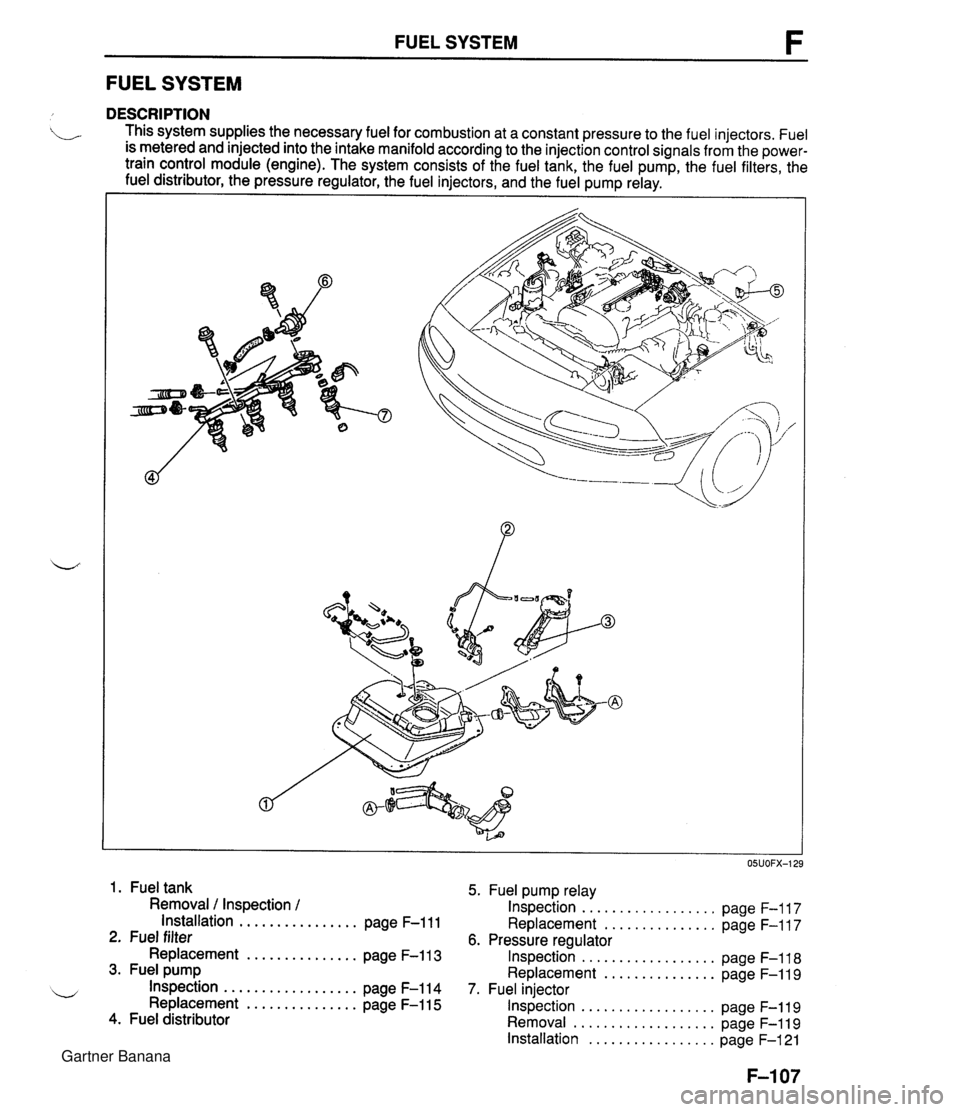
FUEL SYSTEM F FUEL SYSTEM DESCRIPTION . This system supplies the necessary fuel for combustion at a constant pressure to the fuel injectors. Fuel is metered and injected into the intake manifold according to the injection control signals from the power- train control module (engine). The system consists of the fuel tank, the fuel pump, the fuel filters, the fuel distributor, the pressure regulator, the fuel injectors, and the fuel pump relay. I I 1. Fuel tank 5. Fuel pump relay Removal / Inspection / Inspection .................. page F-117 Installation ................ page F-111 Replacement ............... page F-117 2. Fuel filter 6. Pressure regulator Replacement ............... page F-113 Inspection .................. page F-118 3. Fuel pump Replacement ............... page F-119 .................. w Inspection page F-114 7. Fuel injector Replacement ............... page F-115 Inspection .................. page F-119 4. Fuel distributor Removal ................... page F-119 Installation ................. page F-121 Gartner Banana
Page 257 of 1708

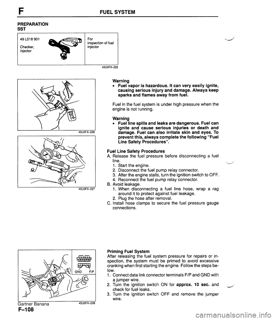
FUEL SYSTEM PREPARATION SST 49 LO1 8 901 For inspection of fuel Checker, injector injector Warning Fuel vapor is hazardous. It can very easily ignite, causing serious injury and damage. Always keep sparks and flames away from fuel. Fuel in the fuel system is under high pressure when the engine is not running. Warning Fuel line spills and leaks are dangerous. Fuel can ignite and cause serious injuries or death and damage. Fuel can also irritate skin and eyes. To prevent this, always complete the following "Fuel Line Safety Procedures". Fuel Line Safety Procedures A. Release the fuel pressure before disconnecting a fuel line. xd 1 . Start the engine. 2. Disconnect the fuel pump relay connector. 3. After the engine stalls, turn the ignition switch to OFF. 4. Reconnect the fuel pump relay connector. B. Avoid leakage. 1. When disconnecting a fuel line hose, wrap a rag around it to protect against fuel leakage. 2. Plug the hose after removal. C. Install hose clamps to secure the fuel pressure gauge connections. Priming Fuel System After releasing the fuel system pressure for repairs or in- spection, the system must be primed to avoid excessive cranking when first starting the engine. Follow the steps be- low. 1. Connect data link connector terminals F/P and GND with a jumper wire. 2. Turn the ignition switch ON for approx. 10 sec. and - check for fuel leaks. 3. Turn the ignition switch OFF and remove the jumper wire. Gartner Banana
Page 258 of 1708

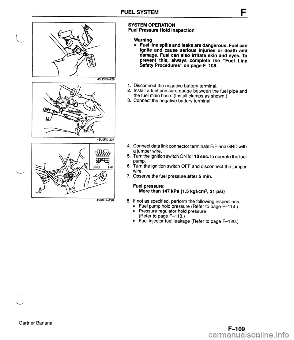
FUEL SYSTEM SYSTEM OPERATION Fuel Pressure Hold Inspection Warning Fuel line spills and leaks are dangerous. Fuel can ignite and cause serious injuries or death and damage. Fuel can also irritate skin and eyes. To prevent this, always complete the "Fuel Line Safety Procedures" on page F-108. 1. Disconnect the negative battery terminal. 2. Install a fuel pressure gauge between the fuel pipe and the fuel main hose. (Install clamps as shown.) 3. Connect the negative battery terminal. 4. Connect data link connector terminals F/P and GND with a jumper wire. 5. Turn the ignition switch ON for 10 sec. to operate the fuel Pump. 6. Turn the ignition switch OFF and disconnect the jumper wire. 7. Observe the fuel pressure after 5 min. Fuel pressure: More than 147 kPa (1.5 kgf/cm2, 21 psi) 8. If not as specified, perform the following inspections. Fuel pump hold pressure (Refer to page F-114.) Pressure regulator hold pressure (Refer to page F-118.) Fuel injector fuel leakage (Refer to page F-120.) Gartner Banana
Page 259 of 1708
FUEL SYSTEM Fuel Line Pressure Inspection Warning Fuel line spills and leaks are dangerous. Fuel can ignite and cause serious injuries or death and damage. Fuel can also irritate skin and eyes. To prevent this, always complete the "Fuel Line Safety Procedures" on page F-108. 1. Disconnect the negative battery terminal. 2. Install a fuel pressure gauge between the fuel pipe and the fuel main hose. (Install clamps as shown.) 3. Connect the negative battery terminal. 4. Connect data link connector terminals F/P and GND with a jumper wire. 5. Turn the ignition switch ON. 6. Measure the fuel line pressure. Fuel line pressure: 265-31 4 kPa {2.7-3.2 kgf/cm2, 38-46 psi) Pressure low- Check fuel pump maximum pressure. (Refer to page F-115.) If as specified, fuel line or fuel filter might be clogged or restricted. Pressure high- Replace the pressure regulator. (Refer to page F-118.) Gartner Banana
Page 260 of 1708

FUEL SYSTEM FUEL TANK Removal 1 Inspection / Installation b Warning Fuel vapor is hazardous. It can very easily ignite, causing serious injury and damage. Always keep sparks and flames away from fuel. Warning Fuel line spills and leaks are dangerous. Fuel can ignite and cause serious injuries or death and damage. Fuel can also irritate skin and eyes. To prevent this, always complete the "Fuel Line Safety Procedures" on page F-108. Warning Repairing a fuel tank that has not been properly steam cleaned can be dangerous. Explosion or fire may cause death or serious injury. Always properly steam clean a fuel tank before re- pairing it. 1. Disconnect the negative battery terminal. 2. Drain the fuel from the fuel tank. 3. Remove the main silencer. (Refer to page F-128.) 4. Remove the power plant frame. (Refer to section J.) 5. Remove in the order shown in the figure, referring to Removal note. 6. Install in the reverse order of removal, referring to Installation note. Gartner Banana