Page 252 of 1708

INTAKE AIR SYSTEM ENGINE ROOM COMPARTMENT 'OR ACCELERATOR PEDAL AND CABLE Accelerator Cable Inspection 1. Check deflection of the cable. If deflection exceeds 1-3mm (0.039-0.118 in), adjust it by turning nut A. 2. Depress the accelerator pedal to the floor and verify that the throttle valve opens fully. Adjust with bolt B if neces- sary. Replacement 1. Remove the accelerator cable from the throttle lever. 2. Loosen the throttle adjustment nuts and remove the cable from the bracket. 3. Compress the tabs of stay C and remove the accelerator cable from the pedal arm. 4. Compress the tabs of stay D and push the cable through the firewall. 5. Remove the accelerator cable. 6. Install in the reverse order of removal. 7. Adiust deflection of the cable after installation. (Refer to I 45~0~~-215 adbve.) Accelerator Pedal Replacement 1. Disconnect the accelerator cable. 2. Remove the accelerator pedal as shown in the figure. 3. Install in the reverse order of removal. ACCELERATOR PEDAL Gartner Banana
Page 257 of 1708

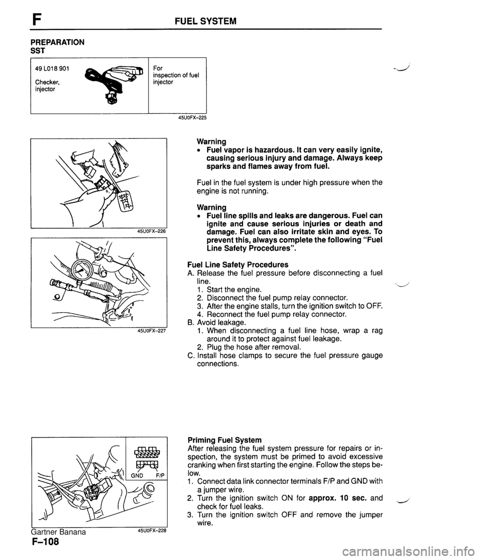
FUEL SYSTEM PREPARATION SST 49 LO1 8 901 For inspection of fuel Checker, injector injector Warning Fuel vapor is hazardous. It can very easily ignite, causing serious injury and damage. Always keep sparks and flames away from fuel. Fuel in the fuel system is under high pressure when the engine is not running. Warning Fuel line spills and leaks are dangerous. Fuel can ignite and cause serious injuries or death and damage. Fuel can also irritate skin and eyes. To prevent this, always complete the following "Fuel Line Safety Procedures". Fuel Line Safety Procedures A. Release the fuel pressure before disconnecting a fuel line. xd 1 . Start the engine. 2. Disconnect the fuel pump relay connector. 3. After the engine stalls, turn the ignition switch to OFF. 4. Reconnect the fuel pump relay connector. B. Avoid leakage. 1. When disconnecting a fuel line hose, wrap a rag around it to protect against fuel leakage. 2. Plug the hose after removal. C. Install hose clamps to secure the fuel pressure gauge connections. Priming Fuel System After releasing the fuel system pressure for repairs or in- spection, the system must be primed to avoid excessive cranking when first starting the engine. Follow the steps be- low. 1. Connect data link connector terminals F/P and GND with a jumper wire. 2. Turn the ignition switch ON for approx. 10 sec. and - check for fuel leaks. 3. Turn the ignition switch OFF and remove the jumper wire. Gartner Banana
Page 268 of 1708

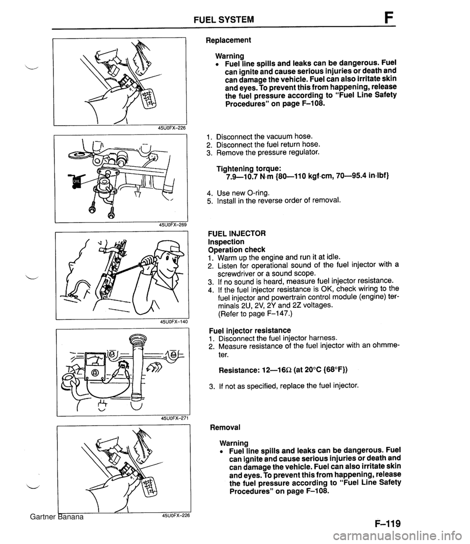
FUEL SYSTEM F Replacement Warning Fuel line spills and leaks can be dangerous. Fuel can ignite and cause serious injuries or death and can damage the vehicle. Fuel can also irritate skin and eyes. To prevent this from happening, release the fuel pressure according to "Fuel Line Safety Procedures" on page F-108. 1. Disconnect the vacuum hose. 2. Disconnect the fuel return hose. 3. Remove the pressure regulator. Tightening torque: 7.9-10.7 N.m (80-11 0 kgf-cm, 70-95.4 in4bf) 4. Use new O-ring. 5. Install in the reverse order of removal. FUEL INJECTOR Inspection Operation check 1. Warm up the engine and run it at idle. 2. Listen for operational sound of the fuel injector with a screwdriver or a sound scope. 3. If no sound is heard, measure fuel injector resistance. 4. If the fuel injector resistance is OK, check wiring to the fuel injector and powertrain control module (engine) ter- minals 2U, 2V1 2Y and 22 voltages. (Refer to page F-147.) Fuel injector resistance 1. Disconnect the fuel injector harness. 2. Measure resistance of the fuel injector with an ohmme- ter. Resistance: 12-16Q (at 20°C (68°F)) 3. If not as specified, replace the fuel injector. Removal Warning Fuel line spills and leaks can be dangerous. Fuel can ignite and cause serious injuries or death and can damage the vehicle. Fuel can also irritate skin and eyes. To prevent this from happening, release the fuel pressure according to "Fuel Line Safety Procedures" on page F-108. Gartner Banana
Page 270 of 1708

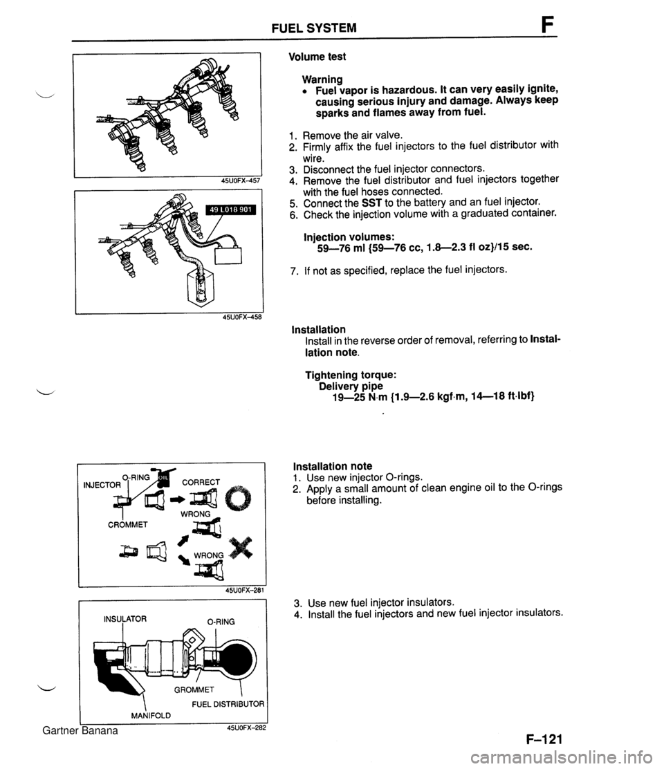
FUEL SYSTEM Volume test Warning Fuel vapor is hazardous. It can very easily ignite, causing serious injury and damage. Always keep sparks and flames away from fuel. 1. Remove the air valve. 2. Firmly affix the fuel injectors to the fuel distributor with wire. 3. Disconnect the fuel injector connectors. 4. Remove the fuel distributor and fuel injectors together with the fuel hoses connected. 5. Connect the SST to the battery and an fuel injector. 6. Check the injection volume with a graduated container. Injection volumes: 59-76 ml (59-76 cc, 1.8-2.3 fl oz}/15 sec. 7. If not as specified, replace the fuel injectors. lnstallation Install in the reverse order of removal, referring to Instal- lation note. Tightening torque: Delivery pipe 19-25 N.m (1 .%2.6 kgfm, 14--18 ft4bf) FUEL DISTRIBUTOR MANIFOLD C 45UOFX-282 Installation note 1. Use new injector O-rings. 2. Apply a small amount of clean engine oil to the O-rings before installing. 45UOFX-281 INSULATOR O-RING 3. Use new fuel injector insulators. 4. Install the fuel injectors and new fuel injector insulators. Gartner Banana
Page 272 of 1708
PRESSURE REGULATOR CONTROL SYSTEM F PRESSURE REGULATOR / f PRC SOLENOID VALVE AIR FILTER U PRC SOLENOID VALVE lnspection (On-vehicle) 1. Start the engine and run it at idle. 2. Disconnect the vacuum hose from the pressure regula- tor. Verify that vacuum is felt. 3. Ground the PRC solenoid valve terminal B with a jumper wire. Verify that no vacuum is felt. 4. If vacuum exists, check the PRC solenoid valve. Inspection 1. Disconnect the vacuum hose from the PRC solenoid valve and vacuum pipe. 2. Blow through the PRC solenoid valve from port A. 3. Verify that air flows from port B. 4. Disconnect the PRC solenoid valve connector. 5. Connect battery positive voltage and a ground to the ter- minals of the PRC solenoid valve. 6. Blow through the PRC solenoid valve from the port A. 7. Verify that air flows from the valve air filter. 8. If not as specified, replace the PRC solenoid valve. Gartner Banana
Page 275 of 1708

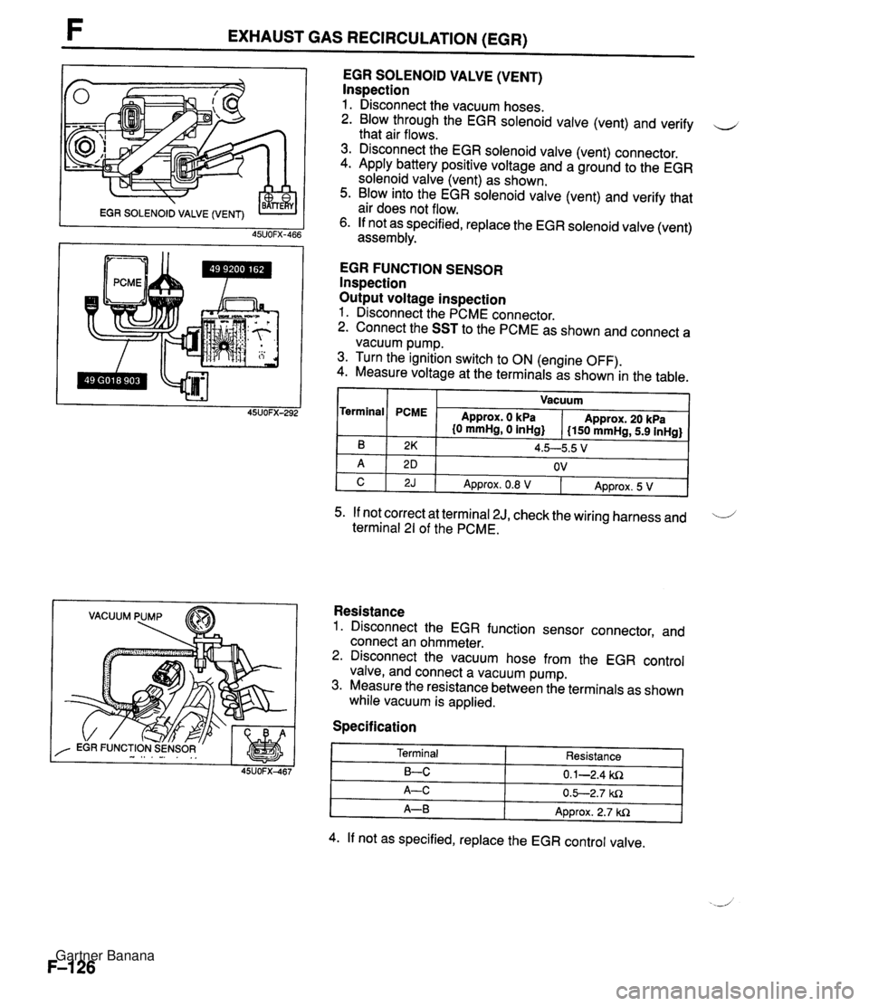
F EXHAUST GAS RECIRCULATION (EGR) VACUUM PUMP EGR SOLENOID VALVE (VENT) lnspection 1. Disconnect the vacuum hoses. 2. Blow through the EGR solenoid valve (vent) and verify u that air flows. 3. Disconnect the EGR solenoid valve (vent) connector. 4. Apply battery positive voltage and a ground to the EGR solenoid valve (vent) as shown. 5. Blow into the EGR solenoid valve (vent) and verify that air does not flow. 6. If not as specified, replace the EGR solenoid valve (vent) assembly. EGR FUNCTION SENSOR lnspection Output voltage inspection 1. Disconnect the PCME connector. 2. Connect the SST to the PCME as shown and connect a vacuum pump. 3. Turn the ignition switch to ON (engine OFF). 4. Measure voltage at the terminals as shown in the table. I I Vacuum I Terminal 5. If not correct at terminal 2J, check the wiring harness and 'i terminal 21 of the PCME. B A C Resistance 1. Disconnect the EGR function sensor connector, and connect an ohmmeter. 2. Disconnect the vacuum hose from the EGR control valve, and connect a vacuum pump. 3. Measure the resistance between the terminals as shown while vacuum is applied. PCME Specification 2K 2 D 2J Approx. 0 kPa {O mmHg, 0 inHg} 4. If not as specified, replace the EGR control valve. Approx. 20 kPa I150 mmHg, 5.9 inHg} 4.5--5.5 V OV Terminal LC A-C A-B Approx. 0.8 V Resistance 0.1-2.4 ki2 0.5-2.7 W1 Approx. 2.7 W1 Approx. 5 V Gartner Banana
Page 280 of 1708

FUEL EVAPORATIVE SYSTEM FUEL EVAPORATIVE SYSTEM DESCRIPTION The fuel evaporative system consists of the fuel vapor valve, the two-way check valve, the charcoal can- ister, the purge solenoid valve, the powertrain control module (engine), and the input devices. The amount of evaporative fumes introduced into the engine and burned is controlled by the solenoid valve in relation to the engine's operating conditions. To maintain the best engine performance, the solenoid valve is controlled by the powertrab control module (engine). THROTTLE 1-1 POSITION SENSOR I1 I I (IDLE SWITCH) 7 BAROMETIC ABSOLUTE PRESSURE SENSOR PARWNEUTRAL SWITCH (AT) MASS AIRFLOW SENSOR CRANKSHAFT POSITION SENSOR (SGT-SIGNAL) n - DUTY - LOW HIGH (ENGINE) CHARCOAL PURGE SOLENOID VALVE CANISTER HEATED OXYGEN SENSOR ENGINE COOLANT POWERTRAIN TEMPERATURE SENSOR CONTROL MODULE CHECK VALVE # 11 FUEL VAPOR VALVE Operation The purge solenoid valve is controlled by duty signals from the powertrain control module (engine) to per- form purging of the charcoal canister. Purging is done when these conditions are met: i/ 1. After warm-up. 2. Driving in gear. 3. Accelerator pedal depressed (idle switch OFF). 4. Heated oxygen sensor functioning normally. Gartner Banana
Page 281 of 1708

FUEL EVAPORATIVE SYSTEM I GROUND I PURGE SOLENOID VALVE On-vehicle lnspection 1. Warm up the engine to normal operating temperature. 2. Run the engine at idle. d 3. Disconnect the vacuum hose from the purge solenoid valve and verify that no vacuum is felt at the purge sole- noid valve. 4. If not as specified, check the purge solenoid valve. lnspection 1. Disconnect the vacuum hoses from the purge solenoid valve. 2. Verify that no air flows through the purge solenoid valve. 3. Disconnect the purge solenoid valve connector and con- nect battery positive voltage and a ground to the termi- nals of the purge solenoid valve. 4. Verify that the air flows through the valve. 5. If not as specified, replace the purge solenoid valve. TWO-WAY CHECK VALVE lnspection 1. Remove the valve. 2. Check the operation of the valve with a vacuum pump. INSTALLATION DIRECTION Specification I Apply approx. 15 mmHg i0.59 inHg} vacuum at port A 1 Airflow I 1 Agply apgrox. 44 mmH~ (1.73 inHd vacuum at Port 6 1 Airflow 1 3. If not as specified, replace the two-way check valve. THREE-WAY CHECK VALVE lnspection 1. Remove the valve and plug the port C. 2. Check operation of the valve with a vacuum pump. Specification 3. If not as specified, replace the three-way check valve. Apply approx. 37 mmHg {I -46 inHg} vacuum at port A Apply approx. 70 mmHg (2.76 inHg} vacuum at port I3 Airflow Airflow -d Gartner Banana