Page 934 of 1708
REAR WINDOW DEFROSTER REAR WINDOW DEFROSTER STRUCTURAL VIEW 1. Rear window defroster L/ 2. Rear window defroster switch 3. Rear window defroster relay 4. Rear window defroster timer unit DESCRIPTION The rear window defroster switch is included in the heater control switch assembly. Gartner Banana
Page 935 of 1708
FUSE BCOCK IX-031 I 1,05);;;! rAR WINOOW OEFROSTER 1-05 --: RELAY FUSE BLOCK 1-2 .CIGARETTE LIGHTER .INTERIOR LIGHT .REAR WINDOW DEFROSTER MAIN FUSE BLOCK FUSE BLOCK W/R (F) -- ;; ROOM L/R (FI IX-04 'OA &g [x-ZZI 1 - eh FUSE CONTROL MOOUCE (EWGINEI (SECTION 8- tc) INSTRVMENT CLUSTER (SECTION C-a) t OOW SWITCHES (SECTION T) INTERIOR LIGHT OFF. ON !;. (I1 OB CIGARETTE L .IGHTER (I) 1-09 INTERIOR LIGHT (11 I I Z-10 REAR WINOOW DEFROSTER SWITCH (I) I Gartner Banana
Page 936 of 1708
REAR WINDOW DEFROSTER T u Symptom: Rear window defroster does not operate. 9MUOTX-232 Step 1 1. Check the following fuses. I Fuse Amperage I Location I 2. If all the fuses are OK, go to Step 2. 3. If a fuse is burned out, replace it. Check and repair the wire harness, if necessary. R.DEF HEATER -- M: Continuity 20A 30A Step 2 1. Disconnect the rear window defroster relay. 2. Apply battery positive voltage and check for continuity between terminals of the relay. B+: Battery positive voltage 3. If correct install the rear window defroster relay and go to Step 3. 4. If not as specified, replace the rear window defroster relay. Fuse box No.2 Main fuse block Step 1 2 C Terminal D 0 GND B 0 B+ A 0 C 0 Gartner Banana
Page 937 of 1708

T REAR WINDOW DEFROSTER Step 3 1. Turn the ignition switch to on. 2. Turn the rear window defroster switch on. 3. Check the voltage at the terminal wires of the rear win- d dow defroster rday connector. B+: Battery positive voltage Terminal (uB) c (R) Step 4 Check if the heater operates in the first position. I Operation I Action I Voltage B+ other NG Repair wiring harness (Heater switch- Rear window defrostertimer unit) Action Check C terminal Repair wiring harness (HEATER fuse - Relav) B+ Other . , Go to Step 4 Go to Step 5 I Step 5 Check the voltage at the rear window defroster connec- tors. Check A terminal Repair wiring harness (DEFOG fuse - Relavl A (w) B+: Battery positive voltage B+ Other Terminal I Voltage I Action B+ I Check C terminal other If all above-mentioned parts are normal, replace the rear window defroster timer unit. Repair wiring harness (Defroster - Defroster timer unit) c (W) A (B) . B+ Other B+ Other Check A terminal Repair wiring harness (Relay- Defroster) Repair wiring harness (Defroster - GND) Repair defroster filament Gartner Banana
Page 994 of 1708
AUDIO T POWER ANTENNA Disassembly 1 Assembly 1. Antenna mast 2. Base 3. Base pad ,, 4. Ground plate 5. Ground base 6. Rod insulator 7. Mast assembly 8. Relay bracket 9. Antenna relay 10. Bracket 11. Motor drive unit 12. Drive mechanism 13. Drive mechanism cover Gartner Banana
Page 995 of 1708
Ix-osl, FUSE ANTENNA BLOCK 1OA 8 R/B J-3 MAIN FUSE BLOCK .POWER ANTENNA MAIN IGNITION m SWITCH L~W PMR ANTENNA MOTOR BR I I T Y w -13 REAR [R) -POHER ANTENNA ASSEMBLY J-14 POWER ANTENNA RELAY I I I Gartner Banana
Page 996 of 1708
AUDIO Inspection c Fuse ness. ml JHFDB If the antenna fails to raise or lower, make the following checks: 1. Check the antenna fuse (10A). 2. Replace fuse after checking and repairing wiring har- Power antenna 1. Check for continuity between the terminals of the power antenna relay. If there is no continuity, replace the relay. Terminal I M: Continuity 2. If the antenna does not function even though there is continuity, the problem may be either in the wiring har- ness or in the audio component assembly. 3. Apply battery positive voltage to the terminals and check the operation. I I A 1 B 1 DOWN I Function of antenna UP Battery Pos. D Neg. A Gartner Banana
Page 1003 of 1708

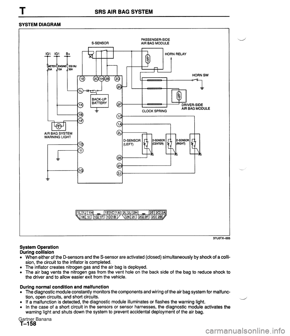
SRS AIR BAG SYSTEM SYSTEM DIAGRAM PASSENGER-SIDE S-SENSOR AIR BAG MODULE I IG1 B+ HORN RELAY CLOCK SPRING BACK-UP BATTERY I AIR BAG SYSTEM WARNING LIGHT SENSOR -7 System Operation During collision When either of the D-sensors and the S-sensor are activated (closed) simultaneously by shock of a colli- sion, the circuit to the inflator is completed. The inflator creates nitrogen gas and the air bag is deployed. The air bag vents the nitrogen gas from the vent hole on the back side of the bag to reduce shock to the driver and to allow easier exit from the vehicle. During normal condition and malfunction The diagnostic module constantly monitors the components and wiring of the air bag system for malfunc- tion, open circuits, and short circuits. .J If a malfunction is detected, the diagnostic module illuminates or flashes the warning light. In the case of a short circuit in the sensors or sensor harnesses, the diagnostic module activates the warning light and shuts down the system to prevent accidental deployment of the air bag. Gartner Banana