1994 JEEP CHEROKEE maintenance
[x] Cancel search: maintenancePage 969 of 1784
pressure is bleeding past the (in-tank mounted) fuel
pump outlet check valve. Replace Fuel Pump Module
assembly. Refer to Fuel Pump Module removal and
installation in this group. If pressure drop is within
specifications, proceed to next step.
(13) Clamp off the rubber hose portion of adapter
tool number 6631 connected to the fuel supply line.
Allow engine to set for 30 minutes. If pressure has
dropped more than 138 kPa (20 psi) in 30 minutes,
pressure is bleeding past the fuel pressure regulator.
Replace fuel pressure regulator. Refer to Fuel Rail
removal and installation in the Component Removal/
Installation section of this group.
MECHANICAL MALFUNCTIONS
Mechanical malfunctions are more difficult to diag-
nose with this system. The powertrain control mod-
ule (PCM) has been programmed to compensate for
some mechanical malfunctions such as incorrect cam
timing, vacuum leaks, etc. If engine performance
problems are encountered and diagnostic trouble
codes are not displayed, the problem may be mechan-
ical rather than electronic.
FUEL FILTER
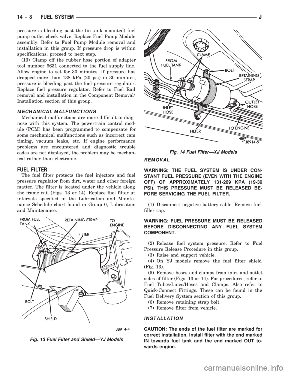
The fuel filter protects the fuel injectors and fuel
pressure regulator from dirt, water and other foreign
matter. The filter is located under the vehicle along
the frame rail (Figs. 13 or 14). Replace fuel filter at
intervals specified in the Lubrication and Mainte-
nance Schedule chart found in Group 0, Lubrication
and Maintenance.
REMOVAL
WARNING: THE FUEL SYSTEM IS UNDER CON-
STANT FUEL PRESSURE (EVEN WITH THE ENGINE
OFF) OF APPROXIMATELY 131-269 KPA (19-39
PSI). THIS PRESSURE MUST BE RELEASED BE-
FORE SERVICING THE FUEL FILTER.
(1) Disconnect negative battery cable. Remove fuel
filler cap.
WARNING: FUEL PRESSURE MUST BE RELEASED
BEFORE DISCONNECTING ANY FUEL SYSTEM
COMPONENT.
(2) Release fuel system pressure. Refer to Fuel
Pressure Release Procedure in this group.
(3) Raise and support vehicle.
(4) On YJ models remove the fuel filter shield
(Fig. 13).
(5) Remove hoses and clamps from inlet and outlet
sides of filter (Figs. 13 or 14). For procedures, refer to
Fuel Tubes/Lines/Hoses and Clamps. Also refer to
Quick-Connect Fittings. These can be found in the
Fuel Delivery System section of this group.
(6) Remove retaining strap bolt.
(7) Remove filter from vehicle.
INSTALLATION
CAUTION: The ends of the fuel filter are marked for
correct installation. Install filter with the end marked
IN towards fuel tank and the end marked OUT to-
wards engine.
Fig. 13 Fuel Filter and ShieldÐYJ Models
Fig. 14 Fuel FilterÐXJ Models
14 - 8 FUEL SYSTEMJ
Page 1446 of 1784
²Noise
²Handling
²Durability
²Tread life
²Traction
²Rolling resistance
²Speed capability
Original equipment tires should be used when re-
placement is needed.
Refer to the placard on the vehicle or the
Owner's Manual for the correct replacement
tire.
Failure to use original or equivalent replacement
tires may adversely affect the handling of the vehi-
cle.
The use of oversize tiresis not recommended.
They may cause interference with vehicle suspension
and steering travel. This can cause tire damage or
failure.
WARNING: FAILURE TO EQUIP THE VEHICLE WITH
TIRES HAVING ADEQUATE LOAD CAPABILITY CAN
RESULT IN SUDDEN TIRE FAILURE.
ROTATION
Tires on the front and rear axles operate at differ-
ent loads and perform different steering, driving, and
braking functions. For these reasons, the tires wear
at unequal rates. They may also develop irregular
wear patterns. These effects can be reduced by rotat-
ing the tires according to the maintenance schedule
in the Owners Manual. This will improve tread life,
traction and maintain a smooth quiet ride.
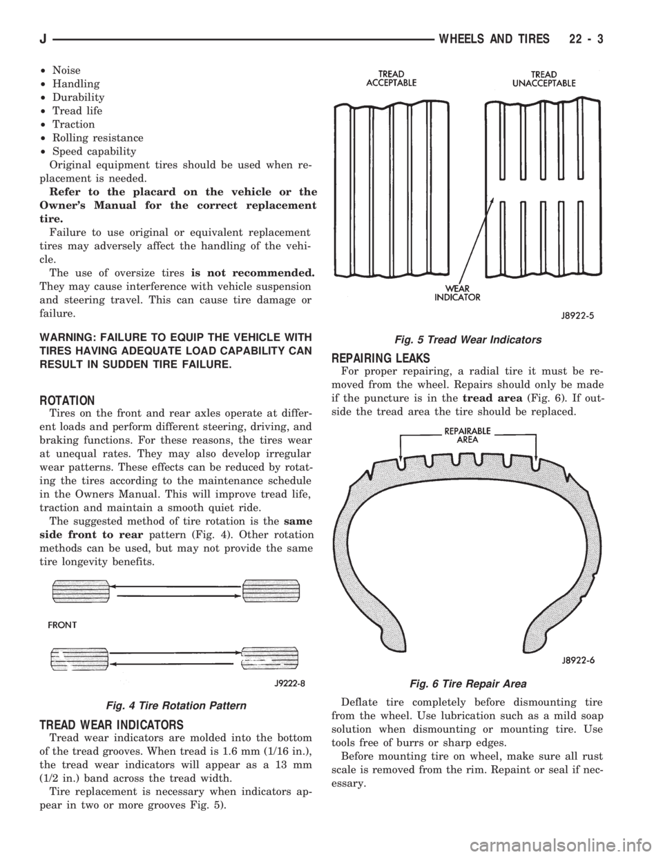
The suggested method of tire rotation is thesame
side front to rearpattern (Fig. 4). Other rotation
methods can be used, but may not provide the same
tire longevity benefits.
TREAD WEAR INDICATORS
Tread wear indicators are molded into the bottom
of the tread grooves. When tread is 1.6 mm (1/16 in.),
the tread wear indicators will appear as a 13 mm
(1/2 in.) band across the tread width.
Tire replacement is necessary when indicators ap-
pear in two or more grooves Fig. 5).
REPAIRING LEAKS
For proper repairing, a radial tire it must be re-
moved from the wheel. Repairs should only be made
if the puncture is in thetread area(Fig. 6). If out-
side the tread area the tire should be replaced.
Deflate tire completely before dismounting tire
from the wheel. Use lubrication such as a mild soap
solution when dismounting or mounting tire. Use
tools free of burrs or sharp edges.
Before mounting tire on wheel, make sure all rust
scale is removed from the rim. Repaint or seal if nec-
essary.
Fig. 4 Tire Rotation Pattern
Fig. 5 Tread Wear Indicators
Fig. 6 Tire Repair Area
JWHEELS AND TIRES 22 - 3
Page 1456 of 1784
BODY COMPONENTSÐXJ VEHICLES
CONTENTS
page page
DOORS............................... 34
EXTERIOR COMPONENTS................. 3
FIXED WINDOW GLASS................. 73GENERAL BODY SERVICE INFORMATION.... 1
INTERIOR COMPONENTS................ 91
UNDERBODY COMPONENTS.............. 84
GENERAL BODY SERVICE INFORMATION
RIGHT HAND DRIVE VEHICLES
The XJ Body Components procedures in this sec-
tion were developed on a left hand drive (LHD) vehi-
cle. Unless a component is unique to a right hand
drive vehicle, it will not be specifically covered in
this section, i.e. cargo barrier. In general, compo-
nents on left hand drive vehicles will be located on
the opposite side in right hand drive vehicles.
LABELS/DECALS/PLATES
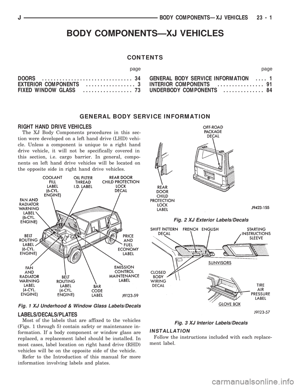
Most of the labels that are affixed to the vehicles
(Figs. 1 through 5) contain safety or maintenance in-
formation. If a body component or window glass are
replaced, a replacement label should be installed. In
most cases, label location on right hand drive (RHD)
vehicles will be on the opposite side of the vehicle.
Refer to the Introduction of this manual for more
information involving labels and plates.
INSTALLATION
Follow the instructions included with each replace-
ment label.
Fig. 1 XJ Underhood & Window Glass Labels/Decals
Fig. 2 XJ Exterior Labels/Decals
Fig. 3 XJ Interior Labels/Decals
JBODY COMPONENTSÐXJ VEHICLES 23 - 1
Page 1635 of 1784
REPLACEMENT
(1) Mark the outline of the existing hinge on the
body and the door with a wax pencil for installation
alignment reference.
When removing the door or hinge DO NOT
discard the plastic shims or the hinge pin.
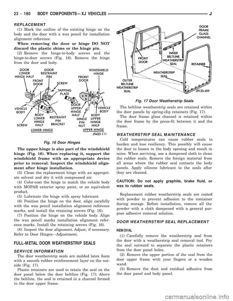
(2) Remove the hinge-to-body screws and the
hinge-to-door screws (Fig. 16). Remove the hinge
from the door and body.
The upper hinge is also part of the windshield
hinge (Fig. 16). When replacing it, support the
windshield frame with an appropriate device
prior to removal. Inspect the windshield align-
ment after hinge installation.
(3) Clean the replacement hinge with an appropri-
ate solvent and dry it with compressed air.
(4) Color-coat the hinge to match the vehicle body
with MOPAR exterior spray paint, or an equivalent
product.
(5) Lubricate the hinge with spray lubricant.
(6) Position the hinge on the door, align carefully
with the wax pencil installation alignment reference
marks, and install the retaining screws (Fig. 16).
(7) Position the hinge on the vehicle body. Align
the wax pencil marks installation alignment refer-
ence marks. Install the retaining screws (Fig. 16).
(8) Inspect the door alignment. Adjust, if necessary.
Refer to Door HingesÐAdjustment.
FULL-METAL DOOR WEATHERSTRIP SEALS
SERVICE INFORMATION
The door weatherstrip seals are molded latex foam
with a smooth rubber reinforcement layer on the out-
side (Fig. 17).
Plastic retainers are used to retain the seal on the
door panel below the door beltline (Fig. 17). Above
the beltline, the seal is retained in a channel formed
in the door upper frame.The beltline weatherstrip seals are retained within
the door panels by spring-clip retainers (Fig. 17).
The door frame glass channel is retained within
the door frame by the press-fit between it and the
frame.
WEATHERSTRIP SEAL MAINTENANCE
Cold temperatures can cause rubber seals to
harden and lose resiliency. This possibly will cause
the door to loosen in the body opening and result in
noise. When servicing, use a dampened cloth to clean
the rubber seals. Remove the foreign material from
all areas where the rubber seal contacts the body
panels. Apply silicone lubricant to the seals after
they are cleaned.
CAUTION: Do not apply graphite, brake fluid, or
wax to rubber seals.
Replacement rubber weatherstrip seals are coated
with powder to prevent adhesion to the container
during storage. Before installation, remove all the
powder with a cloth dampened with a general pur-
pose adhesive removal solution.
DOOR WEATHERSTRIP SEAL REPLACEMENT
REMOVAL
(1) Carefully remove the weatherstrip seal from
the door with a weatherstrip seal removal tool. Pry
the seal outward to separate the plastic retainers
from the door panel holes.
(2) Remove the upper portion of the seal from the
door upper frame with your fingers or a wooden
wand.
(3) Remove the dust and residual adhesive from
the door panel and body panel.
Fig. 17 Door Weatherstrip Seals
Fig. 16 Door Hinges
23 - 180 BODY COMPONENTSÐXJ VEHICLESJ
Page 1669 of 1784
(18) Disconnect the charging hoses from the ser-
vice valves.
COMPRESSOR OIL LEVEL
The compressor oil level must be checked and ad-
justed if the system has been discharged rapidly, or
when a component has been replaced. If a replace-
ment compressor is being installed, it must be filled
with new compressor oil (Suniso 5GS, or equivalent).
The normal quantity of oil required for the com-
pressor and entire system is 136 ml (4.6 fluid oz.) for
SD 709 compressor. DO NOT overfill the compressor.
Excessive amounts of oil in the system will hinder
compressor operation and reduce A/C performance.
CAUTION: The compressor is a high speed unit.
Satisfactory operation is dependent on sufficient lu-
brication; however, excess oil will hinder A/C per-
formance.
Two oil level checking procedures are necessary.
Use Procedure (A) when the compressor is being re-
placed and the system was discharged properly (no
oil loss). Use Procedure (B) for routine maintenance
or when checking oil level after replacing a system
component.
In cases where rapid loss of refrigerant and oil
occurred, the system must be evacuated and
purged. Then the compressor must be filled with
the necessary amount of oil to fill the entire sys-
tem.
PROCEDURE A
(1) Remove the oil filler plug, discharge cap and
suction port caps from the original and replacement
compressor.
(2) Use a clean container to drain the oil from the
replacement compressor. Drain the oil through the
oil filler plug hole, the discharge and suction. Then
rotate clutch front plate several times to push the oil
on cylinder out to discharge chamber of cylinder
head and drain the oil from discharge port.
(3) Drain the oil from the original compressor into
a measuring cup or graduated beaker in the same
way as Step 2. Note the amount of oil drained.
(4) Fill the replacement compressor with the same
amount of oil drained from the original compressor
plus 30 ml (1 fluid oz.).
FOR EXAMPLE:ÐIf the old compressor contained
103.5 ml (3.5 fluid oz.) of oil, fill the replacement
compressor with a total of 133 ml (4.5 fluid oz.) of oil.
PROCEDURE B
(1) Start the engine and operate the engine at idle.
(2) Operate the air conditioning system for 10 min-
utes to return the maximum amount of oil in the sys-
tem to the compressor.(3) Stop the engine and disconnect the magnetic
clutch feed wire.
(4) Front-seat the discharge and suction service
valves.
(5) Determine the mounting angle.
(a) Position an Angle Gauge across the flat sur-
faces of the front mounting ears.
(b) Center the bubble.
(c) Read the mounting angle to the closest de-
gree.
(d) These vehicles should have 0É mounting an-
gle.
(6) Remove the oil filler plug. Position internal
parts by rotation of front plate counterweight to 30É
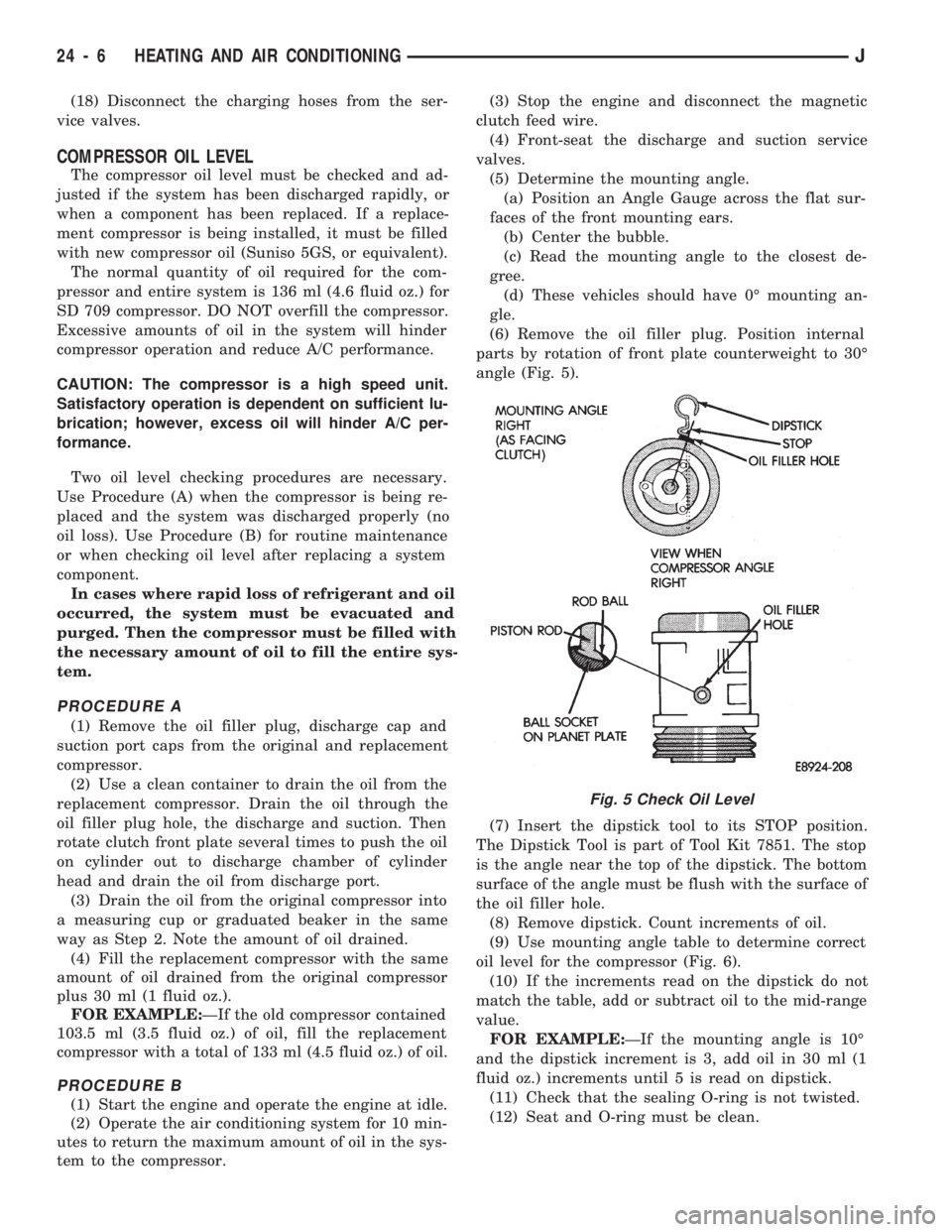
angle (Fig. 5).
(7) Insert the dipstick tool to its STOP position.
The Dipstick Tool is part of Tool Kit 7851. The stop
is the angle near the top of the dipstick. The bottom
surface of the angle must be flush with the surface of
the oil filler hole.
(8) Remove dipstick. Count increments of oil.
(9) Use mounting angle table to determine correct
oil level for the compressor (Fig. 6).
(10) If the increments read on the dipstick do not
match the table, add or subtract oil to the mid-range
value.
FOR EXAMPLE:ÐIf the mounting angle is 10É
and the dipstick increment is 3, add oil in 30 ml (1
fluid oz.) increments until 5 is read on dipstick.
(11) Check that the sealing O-ring is not twisted.
(12) Seat and O-ring must be clean.
Fig. 5 Check Oil Level
24 - 6 HEATING AND AIR CONDITIONINGJ
Page 1719 of 1784
EMISSION CONTROL SYSTEMS
CONTENTS
page page
COMPONENT REMOVAL/INSTALLATION...... 8
EVAPORATIVE EMISSION CONTROLS....... 4EXHAUST EMISSION CONTROLS........... 7
GENERAL INFORMATION.................. 1
GENERAL INFORMATION
INDEX
page page
DRB Scan Tool........................... 2
Service Reminder Indicator (SRI) Lamp......... 1Vacuum Hose Routing Schematics............ 1
Vehicle Emission Control Information (VECI) Label . 1
SERVICE REMINDER INDICATOR (SRI) LAMP
The instrument panel mounted SRI lamp was for-
merly referred to as the emission maintenance re-
minder (EMR) lamp. It isnot usedon any Jeep
model for the 1994 model year.
VEHICLE EMISSION CONTROL INFORMATION
(VECI) LABEL
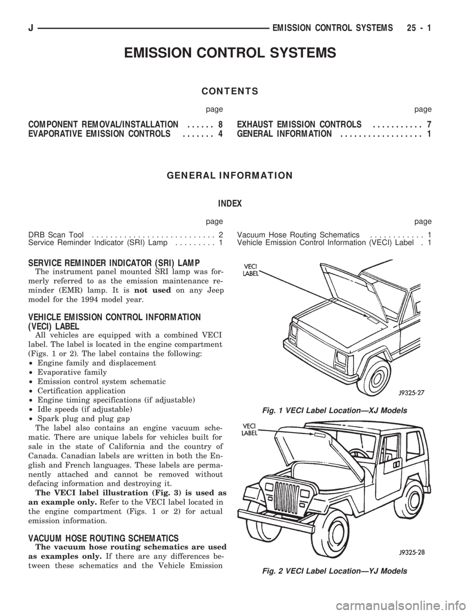
All vehicles are equipped with a combined VECI
label. The label is located in the engine compartment
(Figs. 1 or 2). The label contains the following:
²Engine family and displacement
²Evaporative family
²Emission control system schematic
²Certification application
²Engine timing specifications (if adjustable)
²Idle speeds (if adjustable)
²Spark plug and plug gap
The label also contains an engine vacuum sche-
matic. There are unique labels for vehicles built for
sale in the state of California and the country of
Canada. Canadian labels are written in both the En-
glish and French languages. These labels are perma-
nently attached and cannot be removed without
defacing information and destroying it.
The VECI label illustration (Fig. 3) is used as
an example only.Refer to the VECI label located in
the engine compartment (Figs. 1 or 2) for actual
emission information.
VACUUM HOSE ROUTING SCHEMATICS
The vacuum hose routing schematics are used
as examples only.If there are any differences be-
tween these schematics and the Vehicle Emission
Fig. 1 VECI Label LocationÐXJ Models
Fig. 2 VECI Label LocationÐYJ Models
JEMISSION CONTROL SYSTEMS 25 - 1
Page 1722 of 1784
EVAPORATIVE EMISSION CONTROLS
INDEX
page page
Crankcase Ventilation System................ 5
EVAP (Evaporation) Control System........... 4
EVAP Canister........................... 4Fuel Tank Filler Tube Cap.................. 4
Pressure Relief/Rollover Valve................ 5
EVAP (EVAPORATION) CONTROL SYSTEM
GENERAL INFORMATION
The function of the EVAP control system is to pre-
vent the emissions of gasoline vapors from the fuel
tank into the atmosphere. When fuel evaporates in
the fuel tank, the vapors pass through vent hoses or
tubes to a carbon filled EVAP canister. They are
temporarily held in the canister until they can be
drawn into the intake manifold when the engine is
running.
The EVAP canister is a feature on all models for
the storage of fuel vapors from the fuel tank.
The hoses used in this system are specially
manufactured. If replacement becomes neces-
sary, it is important to use only fuel resistant
hose.
EVAP CANISTER
A sealed, maintenance free, EVAP canister is used
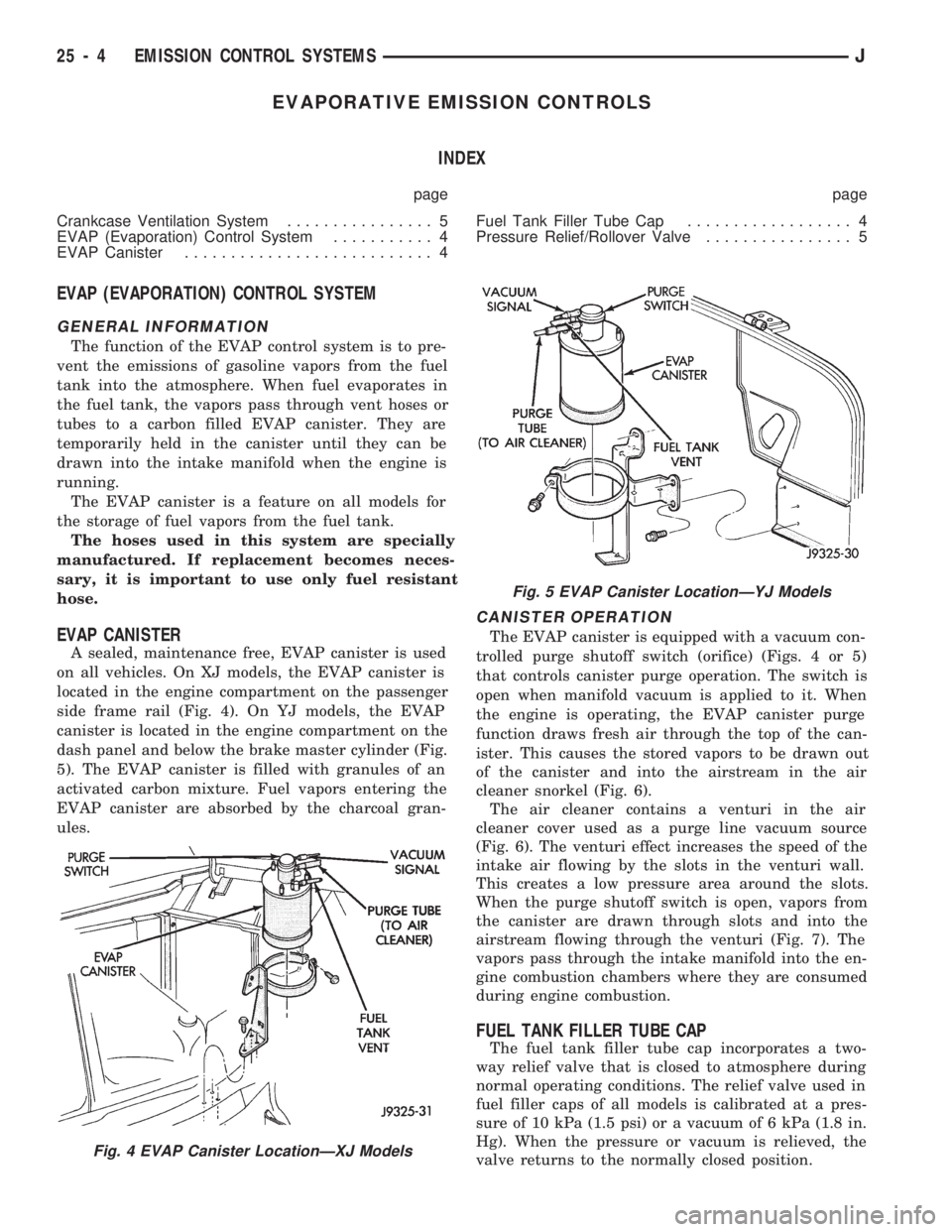
on all vehicles. On XJ models, the EVAP canister is
located in the engine compartment on the passenger
side frame rail (Fig. 4). On YJ models, the EVAP
canister is located in the engine compartment on the
dash panel and below the brake master cylinder (Fig.
5). The EVAP canister is filled with granules of an
activated carbon mixture. Fuel vapors entering the
EVAP canister are absorbed by the charcoal gran-
ules.
CANISTER OPERATION
The EVAP canister is equipped with a vacuum con-
trolled purge shutoff switch (orifice) (Figs. 4 or 5)
that controls canister purge operation. The switch is
open when manifold vacuum is applied to it. When
the engine is operating, the EVAP canister purge
function draws fresh air through the top of the can-
ister. This causes the stored vapors to be drawn out
of the canister and into the airstream in the air
cleaner snorkel (Fig. 6).
The air cleaner contains a venturi in the air
cleaner cover used as a purge line vacuum source
(Fig. 6). The venturi effect increases the speed of the
intake air flowing by the slots in the venturi wall.
This creates a low pressure area around the slots.
When the purge shutoff switch is open, vapors from
the canister are drawn through slots and into the
airstream flowing through the venturi (Fig. 7). The
vapors pass through the intake manifold into the en-
gine combustion chambers where they are consumed
during engine combustion.
FUEL TANK FILLER TUBE CAP
The fuel tank filler tube cap incorporates a two-
way relief valve that is closed to atmosphere during
normal operating conditions. The relief valve used in
fuel filler caps of all models is calibrated at a pres-
sure of 10 kPa (1.5 psi) or a vacuum of 6 kPa (1.8 in.
Hg). When the pressure or vacuum is relieved, the
valve returns to the normally closed position.
Fig. 4 EVAP Canister LocationÐXJ Models
Fig. 5 EVAP Canister LocationÐYJ Models
25 - 4 EMISSION CONTROL SYSTEMSJ
Page 1731 of 1784
NOTE: Groups with the suffix ª-Sº are supplements to
the original service manual publication.
GROUP TAB LOCATOR PAGE
INIntroduction
0Lubrication and Maintenance
2Front Suspension and Axle
3Rear Suspension and Axles
5Brakes
6Clutch
7Cooling System
8Electrical
9Engines
11Exhaust System and Intake Manifold
13Frame and Bumpers
14Fuel System
16Propeller Shafts
19Steering
21Transmissions and Transfer Cases
22Wheels and Tires
23Body Components
24Heating and Air Conditioning
24-SAir Conditioning
25Emission Control Systems
Index
Index Supplement
Service Manual Comment Forms (Rear of Manual)