1994 JEEP CHEROKEE brake sensor
[x] Cancel search: brake sensorPage 394 of 1784
TEST PROCEDURES
INDEX
page page
Checking for Diagnostic Trouble Code......... 5
Electrical Tests at Powertrain Control Module.... 6
Electrical Tests at Servo.................... 5
Inoperative System........................ 5
Operational Check (Road Test)............... 7
Road Test............................... 5Speed Control Switch (Turn Signal Lever) Test . . . 7
Stop Lamp Speed Control Switch Test......... 7
Vacuum Supply Test....................... 7
Vehicle Speed Control System Electrical Tests . . . 5
Vehicle Speed Sensor Test.................. 5
ROAD TEST
Refer to Operational Check (Road Test) section to
verify reports of speed control system malfunction.
INOPERATIVE SYSTEM
Road test vehicle to verify reports of speed control
system malfunction. An inspection should be made
for loose electrical and vacuum connections at the
servo.
Check for correct installation of the vacuum check
valve in the hose from servo to vacuum source. The
word VAC on the valve must point toward the vac-
uum source.
Corrosion should be removed from electrical termi-
nals and a light coating of Mopar MultiPurpose
Grease, or equivalent, applied.
Inspection also should be made to verify that both
ends of the speed control cable are securely attached.
CHECKING FOR DIAGNOSTIC TROUBLE CODE
(1) When trying to verify a speed control system
electronic malfunction use a DRB scan tool to find
the cause (refer to Powertrain Diagnostic Procedures
manual).
If DRB is not available, the Diagnostic Trouble
Code (DTC) may be determined with the following
method:
(a) With key inserted in ignition switch, cycle
switch to ON position 3 times. On third cycle, leave
switch in ON position.
(b) After switch has been cycled 3 times, observe
Malfunction Indicator Lamp (CHECK ENGINE)
on instrument cluster. If a DTC is present, the code
will be displayed in a series of flashes representing
digits. Three flashes in rapid succession, a slight
pause, then 4 flashes in rapid succession would in-
dicate DTC 34.
(2) If a DTC 34 is observed, perform tests in the
sections Electrical Tests at Servo and Electrical Tests
at Powertrain Control Module.
If a DTC 15 is observed, perform test for a faulty
vehicle speed sensor.
(3) Correct any problems found when performing
these tests and recheck for DTC if changes were
made.
VEHICLE SPEED SENSOR TEST
For testing of the vehicle speed sensor and related
components, refer to Powertrain Diagnostic Proce-
dures manual.
VEHICLE SPEED CONTROL SYSTEM ELECTRICAL
TESTS
Vehicle speed control systems may be tested using
two different methods. One involves use of a DRB
scan tool. If this test method is desired, refer to Pow-
ertrain Diagnostic Procedures manual.
The other test method uses a voltmeter. The volt-
meter method is described in the following tests.
If any information is needed concerning wiring, re-
fer to Section 8W - Wiring Diagrams.
CAUTION: When test probing for voltage or conti-
nuity at electrical connectors, care must be taken
not to damage connector, terminals, or seals. If
these components are damaged, intermittent or
complete system failure may occur.
ELECTRICAL TESTS AT SERVO
(1) Turn ignition switch to the ON position. With
speed control switch in the ON position, setup a volt-
meter to read battery voltage and connect negative
lead to a good chassis ground.
(2) Disconnect 4-way connector going to servo
(Figs. 2 and 3). Blue wire with red tracer of main
harness 4-way connector should read approximately
battery voltage. If not, check for loose connections,
brake switch adjustment or, repair main harness as
necessary.
(3) Connect a jumper wire between male and fe-
male terminals of blue wire with red tracer. The
other 3 male terminals from servo should show bat-
tery voltage. If not, replace servo.
(4) Using an ohmmeter, connect one lead to a good
body ground. Touch other lead to black wire terminal
in 4-way connector of main harness. Meter should
show continuity. If not, repair ground circuit as nec-
essary.
JVEHICLE SPEED CONTROL SYSTEM 8H - 5
Page 566 of 1784
WIRING DIAGRAMS YJ
ALPHABETICAL INDEX
Wiring Diagram Name Sheet Number
ABS Accelerator Sensor........................59
ABS Control Module.....................57, 58, 59
ABS Control Module Connector...................60
ABS Motor Pump Relay........................57
ABS Power Relay............................57
A/C Blower Switch............................50
A/C Compressor.............................49
A/C Low Pressure Switch.......................49
A/C Relay.................................49
A/C Thermostat..............................50
Accessory Illumination.........................32
Air Conditioning System (4.0L).................49, 50
A/C Blower Switch..........................50
A/C Compressor............................49
A/C Low Pressure Switch.....................49
A/C Relay................................49
A/C Thermostat............................50
Field Jumper..............................50
Powertrain Control Module.....................49
Anti-Lock Brake System (TEVES).............57, 58, 59
ABS Accelerator Sensor.......................59
ABS Control Module....................57, 58, 59
ABS Motor Pump Relay.......................57
ABS Power Relay...........................57
Brake Pedal Travel Sensor.....................57
Data Link Connector.........................57
Diode..................................58
Hydraulic Actuation Unit......................58
Left Front Wheel Sensor......................59
Left Rear Wheel Sensor.......................59
Power Distribution Center.....................57
Pump Motor..............................57
Pump Motor Sensor.........................57
Right Front Wheel Sensor.....................59
Right Rear Wheel Sensor......................59
Automatic Shut-Down Relay...................11, 17
Back-Up Lamps...........................51, 52
Back-Up Lamp Switch..........................7
Battery................................1,3,5
Blower Motor...............................47
Blower Resistor.............................47
Blower Switch..............................47
Body Harness Connector........................36
Brake Pedal Travel Sensor.......................57
Brake Warning Switch..........................9
Bulkhead Connector........................65, 66
Buzzer Module..............................36
Camshaft Position Sensor....................12, 18
Center High Mounted Stop Lamp..................52
Charging System 2.5L Engine...................3,4
Battery..................................3
Generator.................................3
Power Distribution Center......................4Wiring Diagram Name Sheet Number
Charging System 4.0L Engine...................5,6
Battery..................................5
Generator.................................5
Power Distribution Center......................6
Cigar Lighter...............................24
Circuit Breakers
Headlamp Switch.........................1,29
#11 (W/Wiper).....................2,10,38,39
Clock....................................45
Cluster Connector............................41
Crankshaft Position Sensor...................12, 18
Data Link Connector.....................13, 19, 57
Daytime Running Lamp Module...................28
Dimmer Switch............................1,29
Dome and Courtesy Lamps......................35
Dome Lamp..............................35
Left Courtesy Lamp.........................35
Left Front Door Jamb Switch...................35
Right Courtesy Lamp........................35
Right Front Door Jamb Switch..................35
Dome Lamp................................35
Electrically Tuned Radio with Clock.................45
Electrical Schematic of Cluster....................42
Electrical Schematic of Gauge Package..............44
Electronic Speedometer.........................42
Electronic Tachometer..........................42
Engine Coolant Temp Gauge.....................44
Engine Coolant Temperature Sensor..............15, 21
Engine Oil Pressure and Temperature System..........23
Engine Coolant Temperature Sending Unit...........23
Engine Oil Pressure Sending Unit................23
Engine Oil Pressure Gauge......................44
Engine Starter System........................2,7
Back-Up Lamp Switch........................7
Engine Starter Motor.........................7
Engine Starter Relay..........................7
Park/Neutral Position Switch....................7
Engine Wiring Connector (16 Way).................69
4-WD Command Trac Switch......................8
Field Jumper...............................50
Fog Lamp Relays............................30
Fog Lamp Switch............................30
Front End Lighting.........................25, 26
Left Fog Lamp.............................25
Left Headlamp.............................25
Left Park and Turn Signal Lamp.................25
Left Side Marker Lamp.......................25
Right Fog Lamp............................26
Right Headlamp............................26
Right Park and Turn Signal Lamp................26
Right Side Marker Lamp......................26
Front End Lighting (Canada)...................27, 28
Daytime Running Lamp Module.................28
JWIRING DIAGRAMS 8W - 73
Page 568 of 1784
Wiring Diagram Name Sheet Number
Left Back-Up Lamp..........................51
Left Courtesy Lamp.........................35
Left Fog Lamp..........................25, 27
Left Headlamp..........................25, 27
Left Park and Turn Signal Lamp..............25, 27
Left Side Marker Lamp....................25, 27
Left Tail, Stop and Turn Signal Lamp..............51
Right Back-Up Lamp.........................52
Right Courtesy Lamp........................35
Right Fog Lamp.........................26, 28
Right Headlamp.........................26, 28
Right Park and Turn Signal Lamp.............26, 28
Right Side Marker Lamp...................26, 28
Right Tail, Stop and Turn Signal Lamp.............52
Underhood Lamp............................8
Left Back-Up Lamps..........................51
Left Courtesy Lamp...........................35
Left Fog Lamp...........................25, 27
Left Front Door Jamb Switch.....................35
Left Front Speaker............................46
Left Halo Speaker............................46
Left Headlamp............................25, 27
Left Park and Turn Signal Lamp................25, 27
Left Side Marker Lamp......................25, 27
Left Tail, Stop and Turn Signal Lamp...............51
MAP Sensor.............................15, 21
Mercury Switch..............................8
Modules
ABS Control Module....................57, 58, 59
Buzzer Module.............................36
Daytime Running Lamp Module.................28
Intermittent Wiper Module.....................40
Motors
Blower Motor.............................47
Engine Starter Motor.........................7
Idle Air Control Motor.....................14, 20
Rear Wiper Motor..........................37
Wiper Motor...........................38, 39
Oil Pressure and Temp System...................23
Panel Lamp Dimmer Switch......................1
Panel Lamps.............................31, 32
Accessory Illumination........................32
Heater Control Panel Illumination.................32
Panel Lamp Dimmer Switch....................31
Transmission Range Illumination.................32
Park Brake Switch.............................9
Park/Neutral Position Switch......................7
Part Throttle EMCC 3-Speed Automatic Transmission.....56
Part Throttle EMCC Relay.......................56
Part Throttle EMCC Solenoid.....................56
Power Distribution Center.................1,4,6,57
Power Distribution Center Identification Cover..........67
Power Distribution Center Relays..................68
Power Steering Switch.........................14
Powertrain Control Module............11-22, 48, 49, 56
Powertrain Control Module Connector (2.5L Engine)......63
Powertrain Control Module Connector (4.0L Engine)......64
Provisions for A/C (2.5L).......................48Wiring Diagram Name Sheet Number
Radio Illumination Relay........................45
Radio System............................45, 46
Electrically Tuned Radio with Clock...............45
Left Front Speaker..........................46
Left Halo Speaker...........................46
Radio Illumination Relay......................45
Right Front Speaker.........................46
Right Halo Speaker..........................46
Rear Lighting............................51, 52
Center High Mounted Stop Lamp................52
Left Back-Up Lamp..........................51
Left Tail, Stop & Turn Signal Lamp & License Lamp....51
Right Back-Up Lamp.........................52
Right Tail, Stop & Turn Signal Lamp..............52
Rear Wiper/Washer System......................37
Rear Wiper Motor..........................37
Rear Wiper Switch..........................37
Washer Pump.............................37
Relays
A/C ....................................49
ABS Motor Pump Relay.......................57
ABS Power Relay...........................57
Automatic Shut Down Relay.................11, 17
EMCC...................................56
Engine Starter Relay..........................7
Fog Lamp Relays...........................30
Fuel Pump Relay........................11, 17
Heated Rear Window Relay....................54
Horn Relay...............................33
Radio Illumination Relay......................45
Right Back-Up Lamp..........................52
Right Courtesy Lamp..........................35
Right Fog Lamp...........................26, 28
Right Front Door Jamb Switch....................35
Right Front Speaker...........................46
Right Halo Speaker...........................46
Right Headlamp...........................26, 28
Right Park and Turn Signal...................26, 28
Right Side Marker Lamp.....................26, 28
Right Tail, Stop and Turn Signal Lamp..............52
Seat Belt/Ignition Key Warning Buzzer...............36
Seat Belt Switch.............................36
Sensors
ABS Accelerator Sensor.......................59
Brake Pedal Travel Sensor.....................57
Camshaft Position Sensor...................12, 18
Crankshaft Position Sensor..................12, 18
Engine Coolant Temperature Sensor............15, 21
Heated Oxygen Sensor.....................11, 17
Intake Air Temperature Sensor................15, 21
MAP Sensor...........................15, 21
Pump Motor Sensor.........................57
Throttle Position (Sensor)...................15, 21
Vehicle Speed Sensor.....................12, 18
Wheel Sensors............................59
Speakers..................................46
Speedometer...............................42
JWIRING DIAGRAMS 8W - 75
Page 569 of 1784
Wiring Diagram Name Sheet Number
Splices
Splice A6................................30
Splice A11..............................4,6
Splice A142............................14, 20
Splice A142-1............................3,5
Splice B15...............................58
Splice E2.............................31, 45
Splice F15...............................58
Splice F30.............................24, 45
Splice G5................................10
Splice G7.............................12, 18
Splice G19...............................58
Splice G50............................13, 19
Splice K4.............................15, 21
Splice K4-1............................12, 18
Splice K6.............................15, 21
Splice K7.............................12, 18
Splice K7-1...............................12
Splice L1................................51
Splice L3................................28
Splice L4................................28
Splice L7................................29
Splice L7-1............................26, 28
Splice L7-2...............................51
Splice L39.............................26, 28
Splice L39-1..............................30
Splice M1................................35
Splice M1-1............................8,35
Splice M2................................35
Splice Z1................................32
Splice Z1-2...............................31
Splice Z1-3...............................32
Splice Z1-4...............................54
Splice Z1-5............................51, 54
Splice Z1-6.........................36, 51, 54
Splice Z1-7............................11, 17
Splice Z1-8...............................8
Splice Z1-9............................26, 28
Splice Z1-10.........................25, 27, 37
Splice Z2................................55
Splice Z12...............................57
Starter Relay................................7
Starter System, Engine..........................7
Steering Column Connector......................70
Stop Lamp Switch............................34
Stop/Turn and Hazard Flasher Systems..............34
Hazard Signal Flasher........................34
Stop Lamp Switch..........................34Wiring Diagram Name Sheet Number
Turn/Hazard Switch Assembly...................34
Turn Signal Flasher..........................34
Switches
A/C Blower Switch..........................50
A/C Low Pressure Switch.....................49
Back-Up Lamp Switch........................7
Blower Switch.............................47
Brake Warning Switch.........................9
Dimmer Switch..........................1,29
Door Jamb Switch..........................35
4-WD Drive Switch..........................8
Fog Lamp Switch...........................30
Headlamp Switch.........................1,29
Heated Rear Window Switch....................53
Heater/Off Switch...........................47
Horn Switch..............................33
Ignition Key Warning Switch....................36
Ignition Switch...........................2,9
Mercury Switch.............................8
Panel/Lamp Dimmer Switch..................1,31
Park Brake Switch...........................9
Park/Neutral Position Switch....................7
Power Steering Switch.......................14
Rear Wiper Switch..........................37
Seat Belt Switch...........................36
Stop Lamp Switch..........................34
Washer Switch..........................38, 40
Wiper/Washer Switch......................38, 40
Tachometer................................42
Throttle Position (Sensor)....................15, 21
Timer....................................54
Transmission Range Illumination...................32
Turn/Hazard Switch Assembly....................34
Turn Signal Flasher...........................34
Underhood Light..............................8
Vehicle Speed Sensor.......................12, 18
Voltmeter..................................44
Washer Pump.........................37, 38, 39
Washer Switch...........................38, 40
Wheel Sensors..............................59
Windshield Wiper System.......................38
Washer Pump.............................38
Washer Switch............................38
Wiper Motor..............................38
Wiper/Washer Switch........................38
W/Wiper Circuit Breaker.......................38
Wiper Switch.............................38
8W - 76 WIRING DIAGRAMSJ
Page 642 of 1784
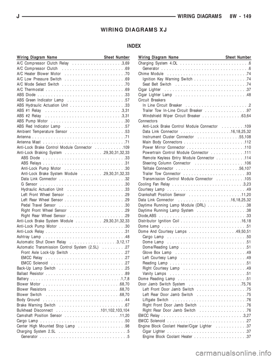
WIRING DIAGRAMS XJ
INDEX
Wiring Diagram Name Sheet Number
A/C Compressor Clutch Relay...................3,69
A/C Compressor Clutch........................69
A/C Heater Blower Motor.......................70
A/C Low Pressure Switch.......................69
A/C Mode Select Switch........................70
A/C Thermostat..............................69
ABS Diode.................................33
ABS Green Indicator Lamp......................57
ABS Hydraulic Actuation Unit.....................33
ABS #1 Relay.............................3,31
ABS #2 Relay.............................3,31
ABS Pump Motor............................30
ABS Red Indicator Lamp.......................57
Ambient Temperature Sensor.....................53
Antenna...................................71
Antenna Mast...............................71
Anti-Lock Brake Control Module Connector...........109
Anti-Lock Braking System...............29,30,31,32,33
ABS Diode...............................33
ABS Relays...............................31
Anti-Lock Pump Motor.......................30
Anti-Lock Brake System Module.........29,30,31,32,33
Data Link Connector.........................32
G Sensor................................30
Hydraulic Actuation Unit......................33
Left Front Wheel Sensor......................29
Left Rear Wheel Sensor.......................29
Pedal Travel Sensor.........................30
Right Front Wheel Sensor.....................29
Right Rear Wheel Sensor......................29
Anti-Lock Brake System Module...........29,30,31,32,33
Anti-Lock Pump Motor.........................30
Anti-Lock Relay..............................31
Ashtray Lamp...............................48
Automatic Shut Down Relay..................3,12,17
Automatic Transmission Control System (2.5L).........27
Front Axle Lock-Up Switch.....................27
EMCC Relay..............................27
EMCC Solenoid............................27
Back-Up Lamp Switch.........................25
Ballast Resistor..............................89
Battery..................................1,7,8
Blower Motor.............................68,70
Blower Resistors...........................68,70
Blower Switch............................68,70
Body Ground...............................44
Brake Warning Switch.........................67
Bulkhead Disconnect.................101,102,103,104
Camshaft Position Sensor.....................11,20
Cargo Lamp................................50
Center High Mounted Stop Lamp..................98
Charging System 2.5L..........................5
Generator.................................5Wiring Diagram Name Sheet Number
Charging System 4.OL..........................6
Generator.................................6
Chime Module..............................74
Ignition Key Warning Switch....................74
Seat Belt Switch...........................74
Cigar Lighter...............................37
Cigar Lighter Lamp...........................48
Circuit Breakers
In Line Circuit Breaker........................2
Trailer Tow In-Line Circuit Breaker................97
Windshield Wiper Circuit Breaker...............63,64
Connectors
Anti-Lock Brake Control Module Connector.........109
Data Link Connector...................16,18,25,32
Instrument Cluster Connector................55,108
Main Body Connectors.......................112
Power Mirror Connector......................110
Powertrain Control Module Connector.............111
Remote Keyless Entry Module Connector...........114
Steering Column Connector...................106
Telltale Connector........................56,107
Trailer Tow Connector........................93
Transmission Control Module Connector...........105
Cooling Fan Relay...........................3,23
Courtesy Lamp..............................49
Crankshaft Position Sensor....................11,20
Data Link Connector....................16,18,25,32
Daytime Running Lamp Module (DRL)...............38
Daytime Running Lamp System...................38
Diode,ABS.................................33
Distributor Ignition Coil.......................16,18
Dome Lamp................................51
Dome And Courtesy Lamps..................49,50,51
Cargo Lamp..............................50
Dome Lamp..............................51
Dome/Reading Lamp.........................51
Glove Box Lamp...........................49
Left Courtesy Lamp.........................49
Reading Lamp.............................51
Right Courtesy Lamp........................49
Vanity Lamps.............................51
Dome Reading Lamp..........................51
Door Jamb Switch System....................75,76
Left Front Door Jamb Switch...................75
Left Rear Door Jamb Switch...................75
Liftgate Switch............................76
Right Front Door Jamb Switch..................76
Right Rear Door Jamb Switch..................76
EMCC Relay...............................3,27
EMCC Solenoid..............................27
Engine Block Coolant Heater/Cigar Lighter............37
Cigar Lighter..............................37
Engine Block Coolant Heater....................37
JWIRING DIAGRAMS 8W - 149
Page 645 of 1784
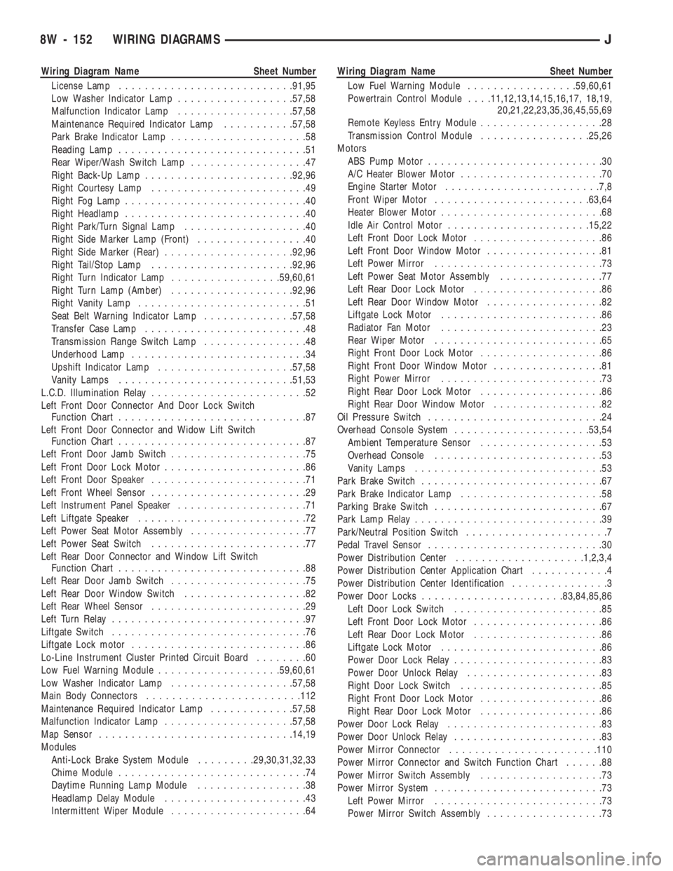
Wiring Diagram Name Sheet Number
License Lamp...........................91,95
Low Washer Indicator Lamp..................57,58
Malfunction Indicator Lamp..................57,58
Maintenance Required Indicator Lamp...........57,58
Park Brake Indicator Lamp.....................58
Reading Lamp.............................51
Rear Wiper/Wash Switch Lamp..................47
Right Back-Up Lamp.......................92,96
Right Courtesy Lamp........................49
Right Fog Lamp............................40
Right Headlamp............................40
Right Park/Turn Signal Lamp...................40
Right Side Marker Lamp (Front).................40
Right Side Marker (Rear)....................92,96
Right Tail/Stop Lamp......................92,96
Right Turn Indicator Lamp.................59,60,61
Right Turn Lamp (Amber)...................92,96
Right Vanity Lamp..........................51
Seat Belt Warning Indicator Lamp..............57,58
Transfer Case Lamp.........................48
Transmission Range Switch Lamp................48
Underhood Lamp...........................34
Upshift Indicator Lamp.....................57,58
Vanity Lamps...........................51,53
L.C.D. Illumination Relay........................52
Left Front Door Connector And Door Lock Switch
Function Chart.............................87
Left Front Door Connector and Widow Lift Switch
Function Chart.............................87
Left Front Door Jamb Switch.....................75
Left Front Door Lock Motor......................86
Left Front Door Speaker........................71
Left Front Wheel Sensor........................29
Left Instrument Panel Speaker....................71
Left Liftgate Speaker..........................72
Left Power Seat Motor Assembly..................77
Left Power Seat Switch........................77
Left Rear Door Connector and Window Lift Switch
Function Chart.............................88
Left Rear Door Jamb Switch.....................75
Left Rear Door Window Switch...................82
Left Rear Wheel Sensor........................29
Left Turn Relay..............................97
Liftgate Switch..............................76
Liftgate Lock motor...........................86
Lo-Line Instrument Cluster Printed Circuit Board........60
Low Fuel Warning Module...................59,60,61
Low Washer Indicator Lamp...................57,58
Main Body Connectors........................112
Maintenance Required Indicator Lamp.............57,58
Malfunction Indicator Lamp....................57,58
Map Sensor..............................14,19
Modules
Anti-Lock Brake System Module.........29,30,31,32,33
Chime Module.............................74
Daytime Running Lamp Module.................38
Headlamp Delay Module......................43
Intermittent Wiper Module.....................64Wiring Diagram Name Sheet Number
Low Fuel Warning Module.................59,60,61
Powertrain Control Module. . . .11,12,13,14,15,16,17, 18,19,
20,21,22,23,35,36,45,55,69
Remote Keyless Entry Module...................28
Transmission Control Module.................25,26
Motors
ABS Pump Motor...........................30
A/C Heater Blower Motor......................70
Engine Starter Motor........................7,8
Front Wiper Motor........................63,64
Heater Blower Motor.........................68
Idle Air Control Motor......................15,22
Left Front Door Lock Motor....................86
Left Front Door Window Motor..................81
Left Power Mirror..........................73
Left Power Seat Motor Assembly................77
Left Rear Door Lock Motor....................86
Left Rear Door Window Motor..................82
Liftgate Lock Motor.........................86
Radiator Fan Motor.........................23
Rear Wiper Motor..........................65
Right Front Door Lock Motor...................86
Right Front Door Window Motor.................81
Right Power Mirror.........................73
Right Rear Door Lock Motor...................86
Right Rear Door Window Motor.................82
Oil Pressure Switch...........................24
Overhead Console System.....................53,54
Ambient Temperature Sensor...................53
Overhead Console..........................53
Vanity Lamps.............................53
Park Brake Switch............................67
Park Brake Indicator Lamp......................58
Parking Brake Switch..........................67
Park Lamp Relay.............................39
Park/Neutral Position Switch......................7
Pedal Travel Sensor...........................30
Power Distribution Center....................1,2,3,4
Power Distribution Center Application Chart............4
Power Distribution Center Identification...............3
Power Door Locks......................83,84,85,86
Left Door Lock Switch.......................85
Left Front Door Lock Motor....................86
Left Rear Door Lock Motor....................86
Liftgate Lock Motor.........................86
Power Door Lock Relay.......................83
Power Door Unlock Relay.....................83
Right Door Lock Switch......................85
Right Front Door Lock Motor...................86
Right Rear Door Lock Motor...................86
Power Door Lock Relay........................83
Power Door Unlock Relay.......................83
Power Mirror Connector.......................110
Power Mirror Connector and Switch Function Chart......88
Power Mirror Switch Assembly...................73
Power Mirror System..........................73
Left Power Mirror..........................73
Power Mirror Switch Assembly..................73
8W - 152 WIRING DIAGRAMSJ
Page 647 of 1784
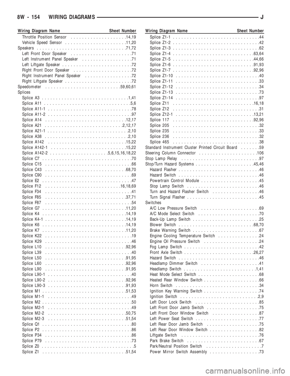
Wiring Diagram Name Sheet Number
Throttle Position Sensor....................14,19
Vehicle Speed Sensor......................11,20
Speakers................................71,72
Left Front Door Speaker......................71
Left Instrument Panel Speaker..................71
Left Liftgate Speaker.........................72
Right Front Door Speaker.....................72
Right Instrument Panel Speaker.................72
Right Liftgate Speaker........................72
Speedometer...........................59,60,61
Splices
Splice A3...............................1,41
Splice A11...............................5,6
Splice A11-1..............................78
Splice A11-2..............................97
Splice A14.............................12,17
Splice A21............................2,12,17
Splice A21-1.............................2,10
Splice A38..............................2,10
Splice A142............................15,22
Splice A142-1...........................15,22
Splice A142-2.....................5,6,15,16,18,22
Splice C7................................70
Splice C15...............................66
Splice C43.............................68,70
Splice C90...............................69
Splice E2................................47
Splice F12...........................16,18,69
Splice F34...............................41
Splice F85.............................37,71
Splice F87...............................54
Splice G7..............................11,20
Splice K4..............................14,19
Splice K4-1.............................14,19
Splice K6..............................14,19
Splice K7..............................11,20
Splice K22...............................19
Splice K29...............................46
Splice L10.............................92,96
Splice L39...............................40
Splice L50.............................91,95
Splice L60.............................92,96
Splice L90.............................91,95
Splice L90-1..............................40
Splice L90-2............................92,96
Splice L90-3............................91,93
Splice M1..............................51,53
Splice M1-1..............................49
Splice M2................................50
Splice M2-1..............................49
Splice M2-2............................50,75
Splice M2-3............................51,54
Splice Q1................................80
Splice P2................................86
Splice P34...............................86
Splice P79...............................73
Splice Z0.................................5
Splice Z1..............................51,54Wiring Diagram Name Sheet Number
Splice Z1-1...............................44
Splice Z1-2...............................42
Splice Z1-3...............................62
Splice Z1-4.............................63,64
Splice Z1-5.............................44,66
Splice Z1-6.............................91,93
Splice Z1-7.............................92,96
Splice Z1-10..............................40
Splice Z1-11..............................33
Splice Z1-12..............................34
Splice Z1-13..............................73
Splice Z1-14..............................97
Splice Z11.............................16,18
Splice Z12...............................31
Splice Z12-1............................13,21
Splice 117.............................92,96
Splice 205...............................32
Splice 235...............................33
Splice 236...............................32
Splice 465...............................38
Standard Instrument Cluster Printed Circuit Board.......59
Steering Column Connector.....................106
Stop Lamp Relay............................97
Stop/Turn Hazard Systems.....................45,46
Hazard Flasher.............................46
Hazard Switch.............................46
Powertrain Control Module.....................45
Stop Lamp Switch..........................46
Turn and Hazard Flasher Switch.................46
Turn Signal Flasher..........................45
Switches
A/C Low Pressure Switch.....................69
A/C Mode Select Switch......................70
Back-Up Lamp Switch........................25
Blower Switch...........................68,70
Brake Warning Switch........................67
Engine Cooling Temperature Switch...............24
Engine Oil Pressure Switch....................24
Fog Lamp Switch...........................42
Front Axle Switch.........................26,27
Hazard Switch.............................46
Headlamp Dimmer Switch.....................41
Headlamp Switch..........................1,41
Heat Mode Select Switch......................68
Heated Rear Window Switch....................66
Horn Switch..............................34
Ignition Key Warning Switch....................74
Ignition Switch............................2,9
Left Door Lock Switch.......................85
Left Front Door Jamb Switch...................75
Left Front Door Window Switch.................87
Left Power Seat Switch.......................77
Left Rear Door Jamb Switch...................75
Left Rear Door Window Switch..................82
Liftgate Switch............................76
Park Brake Switch..........................67
Park/Neutral Position Switch....................7
Power Mirror Switch Assembly..................73
8W - 154 WIRING DIAGRAMSJ
Page 764 of 1784
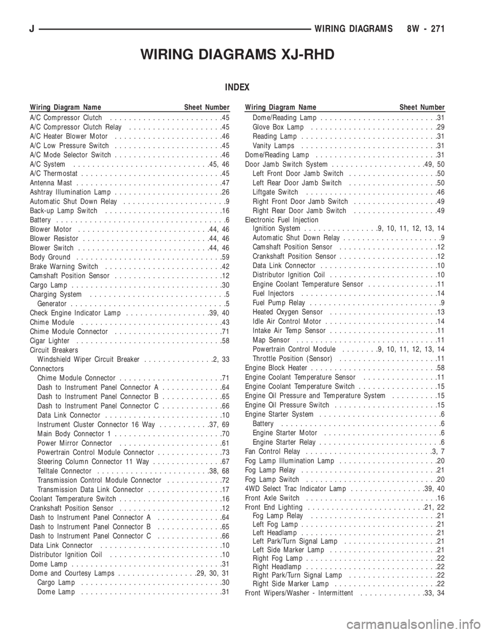
WIRING DIAGRAMS XJ-RHD
INDEX
Wiring Diagram Name Sheet Number
A/C Compressor Clutch........................45
A/C Compressor Clutch Relay....................45
A/C Heater Blower Motor.......................46
A/C Low Pressure Switch.......................45
A/C Mode Selector Switch.......................46
A/C System.............................45, 46
A/C Thermostat..............................45
Antenna Mast...............................47
Ashtray Illumination Lamp.......................26
Automatic Shut Down Relay......................9
Back-up Lamp Switch.........................16
Battery....................................6
Blower Motor............................44, 46
Blower Resistor...........................44, 46
Blower Switch............................44, 46
Body Ground...............................59
Brake Warning Switch.........................42
Camshaft Position Sensor.......................12
Cargo Lamp................................30
Charging System.............................5
Generator.................................5
Check Engine Indicator Lamp..................39, 40
Chime Module..............................43
Chime Module Connector.......................71
Cigar Lighter...............................58
Circuit Breakers
Windshield Wiper Circuit Breaker...............2,33
Connectors
Chime Module Connector......................71
Dash to Instrument Panel Connector A.............64
Dash to Instrument Panel Connector B.............65
Dash to Instrument Panel Connector C.............66
Data Link Connector.........................10
Instrument Cluster Connector 16 Way...........37, 69
Main Body Connector 1.......................70
Power Mirror Connector......................61
Powertrain Control Module Connector..............73
Steering Column Connector 11 Way...............67
Telltale Connector........................38, 68
Transmission Control Module Connector............72
Transmission Data Link Connector................17
Coolant Temperature Switch......................16
Crankshaft Position Sensor......................12
Dash to Instrument Panel Connector A..............64
Dash to Instrument Panel Connector B..............65
Dash to Instrument Panel Connector C..............66
Data Link Connector..........................10
Distributor Ignition Coil........................10
Dome Lamp................................31
Dome and Courtesy Lamps.................29, 30, 31
Cargo Lamp..............................30
Dome Lamp..............................31Wiring Diagram Name Sheet Number
Dome/Reading Lamp.........................31
Glove Box Lamp...........................29
Reading Lamp.............................31
Vanity Lamps.............................31
Dome/Reading Lamp..........................31
Door Jamb Switch System....................49, 50
Left Front Door Jamb Switch...................50
Left Rear Door Jamb Switch...................50
Liftgate Switch............................46
Right Front Door Jamb Switch..................49
Right Rear Door Jamb Switch..................49
Electronic Fuel Injection
Ignition System................9,10,11,12,13,14
Automatic Shut Down Relay.....................9
Camshaft Position Sensor.....................12
Crankshaft Position Sensor.....................12
Data Link Connector.........................10
Distributor Ignition Coil.......................10
Engine Coolant Temperature Sensor...............11
Fuel Injectors.............................14
Fuel Pump Relay............................9
Heated Oxygen Sensor.......................13
Idle Air Control Motor........................14
Intake Air Temp Sensor.......................11
Map Sensor..............................11
Powertrain Control Module........9,10,11,12,13,14
Throttle Position (Sensor).....................11
Engine Block Heater...........................58
Engine Coolant Temperature Sensor................11
Engine Coolant Temperature Switch.................15
Engine Oil Pressure and Temperature System..........15
Engine Oil Pressure Switch......................15
Engine Starter System..........................6
Battery..................................6
Engine Starter Motor.........................6
Engine Starter Relay..........................6
Fan Control Relay...........................3,7
Fog Lamp Illumination Lamp.....................20
Fog Lamp Relay.............................21
Fog Lamp Switch............................20
4WD Select Trac Indicator Lamp................39, 40
Front Axle Switch............................16
Front End Lighting.........................21, 22
Fog Lamp Relay...........................21
Left Fog Lamp.............................21
Left Headlamp.............................21
Left Park/Turn Signal Lamp....................21
Left Side Marker Lamp.......................21
Right Fog Lamp............................22
Right Headlamp............................22
Right Park/Turn Signal Lamp...................22
Right Side Marker Lamp......................22
Front Wipers/Washer - Intermittent..............33, 34
JWIRING DIAGRAMS 8W - 271