1994 JEEP CHEROKEE transmission fluid
[x] Cancel search: transmission fluidPage 218 of 1784
CLUTCH DIAGNOSIS
INDEX
page page
Clutch Problem Causes..................... 3
General Diagnosis Information................ 3Inspection and Diagnosis Charts.............. 4
GENERAL DIAGNOSIS INFORMATION
Unless the cause of a clutch problem is obvious, ac-
curate problem diagnosis will usually require a road
test to confirm a problem. Component inspection will
then be required to determine the actual problem
cause.
During a road test, drive the vehicle at normal
speeds. Shift the transmission through all gear
ranges and observe clutch action. If chatter, grab,
slip, or improper release is experienced, remove and
inspect the clutch components. However, if the prob-
lem is noise or hard shifting, further diagnosis may
be needed as the transmission or another driveline
component may be at fault. Careful observation dur-
ing the test will help narrow the problem area.
CLUTCH PROBLEM CAUSES
CONTAMINATION
Fluid contamination is a frequent cause of clutch
malfunctions. Oil, water, or clutch fluid on the clutch
contact surfaces will cause faulty operation. The
usual result is chatter, slip and grab.
During inspection, note if any components are con-
taminated with oil, hydraulic fluid, or water/road
splash.
Oil contamination indicates a leak at either the
rear main seal or transmission input shaft. Oil leak-
age produces a residue of oil on the housing interior
and on the clutch cover and flywheel. Heat buildup
caused by slippage between the cover, disc and fly-
wheel, can sometimes bake the oil residue onto the
components. The glaze-like residue ranges in color
from amber to black.
Road splash contamination means dirt/water is en-
tering the clutch housing due to loose bolts, housing
cracks, or through hydraulic line openings. Driving
through deep water puddles can force water/road
splash into the housing through such openings.
Clutch fluid leaks are from loose or damaged slave
cylinder fluid lines and connecting fittings. However,
clutch fluid leaks will usually be noted and corrected
before severe contamination occurs.
CLUTCH MISALIGNMENT
Clutch components must be in proper alignment
with the crankshaft and transmission input shaft.Misalignment caused by excessive runout or warpage
of any clutch component will cause grab, chatter and
improper clutch release.
Flywheel Runout
Check flywheel runout whenever misalignment is
suspected. Flywheel runout should not exceed 0.08
mm (0.003 in.). Measure runout at the outer edge of
the flywheel face with a dial indicator. Mount the in-
dicator on a stud installed in place of one of the fly-
wheel bolts.
Common causes of runout are:
²heat warpage
²improper machining
²incorrect bolt tightening
²improper seating on crankshaft flange shoulder
²foreign material on crankshaft flange
Flywheel machining is not recommended. The fly-
wheel clutch surface is machined to a unique contour
and machining will negate this feature. However,
minor flywheel scoring can be cleaned up by hand
with 180 grit emery, or with surface grinding equip-
ment. Remove only enough material to reduce scor-
ing (approximately 0.001 - 0.003 in.). Heavy stock
removal isnot recommended.Replace the flywheel
if scoring is severe and deeper than 0.076 mm (0.003
in.). Excessive stock removal can result in flywheel
cracking or warpage after installation; it can also
weaken the flywheel and interfere with proper clutch
release.
Clean the crankshaft flange before mounting the
flywheel. Dirt and grease on the flange surface may
cock the flywheel causing excessive runout. Use new
bolts when remounting a flywheel and secure the
bolts with Mopar Lock And Seal. Tighten flywheel
bolts to specified torque only. Overtightening can dis-
tort the flywheel hub causing runout.
Clutch Cover And Disc Runout
Check the clutch disc before installation. Axial
(face) runout of anewdisc should not exceed 0.50
mm (0.020 in.). Measure runout about 6 mm (1/4 in.)
from the outer edge of the disc facing. Obtain an-
other disc if runout is excessive.
Check condition of the clutch before installation. A
warped cover or diaphragm spring will cause grab
and incomplete release or engagement. Be careful
JCLUTCH DIAGNOSIS 6 - 3
Page 225 of 1784
CLUTCH SERVICE
INDEX
page page
Clutch Cover and Disc Installation............ 10
Clutch Cover and Disc Removal............. 10
Clutch Fluid Level........................ 14
Clutch Housing Replacement................ 11
Clutch Hydraulic Linkage Installation.......... 12
Clutch Hydraulic Linkage Removal........... 11Clutch Pedal Installation................... 15
Clutch Pedal Removal..................... 15
Clutch Safety Precautions.................. 10
Flywheel Service......................... 15
Pilot Bearing Replacement................. 11
Release Bearing Replacement............... 11
CLUTCH SAFETY PRECAUTIONS
WARNING: EXERCISE CARE WHEN SERVICING
CLUTCH COMPONENTS. DUST AND DIRT ON
CLUTCH PARTS USE MAY CONTAIN ASBESTOS FI-
BERS. BREATHING EXCESSIVE CONCENTRATIONS
OF THESE FIBERS CAN CAUSE SERIOUS BODILY
HARM. WEAR A RESPIRATOR DURING SERVICE
AND NEVER CLEAN CLUTCH COMPONENTS WITH
COMPRESSED AIR OR WITH A DRY BRUSH. EI-
THER CLEAN THE COMPONENTS WITH A WATER
DAMPENED RAGS OR USE A VACUUM CLEANER
SPECIFICALLY DESIGNED FOR REMOVING ASBES-
TOS FIBERS AND DUST. DO NOT CREATE DUST
BY SANDING A CLUTCH DISC. REPLACE THE DISC
IF THE FRICTION MATERIAL IS DAMAGED OR
CONTAMINATED. DISPOSE OF ALL DUST AND
DIRT CONTAINING ASBESTOS FIBERS IN SEALED
BAGS OR CONTAINERS. THIS WILL HELP MINIMIZE
EXPOSURE TO YOURSELF AND TO OTHERS. FOL-
LOW ALL RECOMMENDED SAFETY PRACTICES
PRESCRIBED BY THE OCCUPATIONAL SAFETY
AND HEALTH ADMINISTRATION (OSHA) AND THE
ENVIRONMENTAL SAFETY AGENCY (EPA), FOR
THE HANDLING AND DISPOSAL OF PRODUCTS
CONTAINING ASBESTOS.
CLUTCH COVER AND DISC REMOVAL
(1) Remove transmission. Refer to procedures in
Group 21.
(2) If original clutch cover will be reinstalled,
mark position of cover on flywheel for assembly ref-
erence. Use paint or a scriber for this purpose.
(3) If clutch cover is to be replaced, cover bolts can
be removed in any sequence. However, if original
cover will be reinstalled, loosen cover bolts evenly
and in rotation to relieve spring tension equally.
This is necessary avoid warping cover.
(4) Remove cover bolts and remove cover and disc
(Fig. 2).
CLUTCH COVER AND DISC INSTALLATION
(1) Lightly scuff sand flywheel face with 180 grit
emery cloth. Then clean surface with a wax and
grease remover.
(2) Lubricate pilot bearing with Mopar high tem-
perature bearing grease.
(3) Check runout and free operation of new clutch
disc as follows:
(a) Slide disc onto transmission input shaft
splines. Disc should slide freely on splines.
(b) Leave disc on shaft and check face runout
with dial indicator. Check runout at disc hub and
about 6 mm (1/4 in.) from outer edge of facing.
(c) Face runout should not exceed 0.5 mm (0.020
in.). Obtain another clutch disc if runout exceeds
this limit.
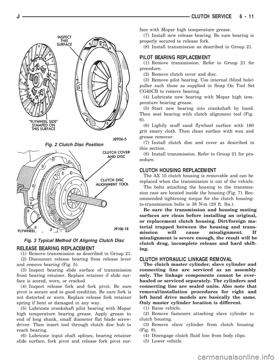
(4) Position clutch disc on flywheel. Be sure side of
disc marked flywheel side is positioned against fly-
wheel (Fig. 2). If disc is not marked, be sure flat side
of disc hub is toward flywheel.
(5) Insert clutch alignment tool in clutch disc (Fig.
3).
(6) Insert alignment tool in pilot bearing and posi-
tion disc on flywheel. Be sure disc hub is positioned
correctly. Side of hub marked Flywheel Side should
face flywheel (Fig. 2). If disc is not marked, place flat
side of disc against flywheel.
(7) Position clutch cover over disc and on flywheel
(Fig. 3).
(8) Install clutch cover bolts finger tight.
(9) Tighten cover bolts evenly and in rotation a
few threads at a time.Cover bolts must be tight-
ened evenly and to specified torque to avoid dis-
torting cover. Tightening torques are 31 Nzm (23
ft. lbs.) on 2.5L engines and 54 Nzm (40 ft. lbs.) on
4.0L engines.
(10) Apply light coat of Mopar high temperature
bearing grease to pilot bearing hub and splines of
transmission input shaft.Do not overlubricate
shaft splines. This will result in grease contami-
nation of disc.
(11) Install transmission (Fig. 4). Refer to proce-
dures in Group 21.
6 - 10 CLUTCH SERVICEJ
Page 226 of 1784
RELEASE BEARING REPLACEMENT
(1) Remove transmission as described in Group 21.
(2) Disconnect release bearing from release lever
and remove bearing (Fig. 5).
(3) Inspect bearing slide surface of transmission
front bearing retainer. Replace retainer if slide sur-
face is scored, worn, or cracked.
(4) Inspect release fork and fork pivot. Be sure
pivot is secure and in good condition. Be sure fork is
not distorted or worn. Replace release fork retainer
spring if bent or damaged in any way.
(5) Lubricate crankshaft pilot bearing with Mopar
high temperature bearing grease. Apply grease to
end of long shank, small diameter flat blade screw-
driver. Then insert tool through clutch disc hub to
reach bearing.
(6) Lubricate input shaft splines, bearing retainer
slide surface, fork pivot and release fork pivot sur-face with Mopar high temperature grease.
(7) Install new release bearing. Be sure bearing is
properly secured to release fork.
(8) Install transmission as described in Group 21.
PILOT BEARING REPLACEMENT
(1) Remove transmission. Refer to Group 21 for
procedure.
(2) Remove clutch cover and disc.
(3) Remove pilot bearing. Use internal (blind hole)
puller such those as supplied in Snap On Tool Set
CG40CB to remove bearing.
(4) Lubricate new bearing with Mopar high tem-
perature bearing grease.
(5) Start new bearing into crankshaft by hand.
Then seat bearing with clutch alignment tool (Fig.
6).
(6) Lightly scuff sand flywheel surface with 180
grit emery cloth. Then clean surface with wax and
grease remover.
(7) Install clutch disc and cover as described in
this section.
(8) Install transmission. Refer to Group 21 for pro-
cedure.
CLUTCH HOUSING REPLACEMENT
The AX 15 clutch housing is removable and can be
replaced when the transmission is out of the vehicle.
The bolts attaching the housing to the transmis-
sion case are located inside the housing (Fig. 7). Rec-
ommended tightening torque for the clutch housing-
to-transmission bolts is 38 Nzm (28 ft. lbs.).
Be sure the transmission and housing mating
surfaces are clean before installing an original,
or replacement clutch housing. Dirt/foreign ma-
terial trapped between the housing and trans-
mission will cause misalignment. If
misalignment is severe enough, the result will be
clutch drag, incomplete release and hard shift-
ing.
CLUTCH HYDRAULIC LINKAGE REMOVAL
The clutch master cylinder, slave cylinder and
connecting line are serviced as an assembly
only. The linkage components cannot be over-
hauled or serviced separately. The cylinders and
connecting line are sealed units. Also note that
removal/installation procedures for right and
left hand drive models are basically the same.
Only master cylinder location is different.
(1) Raise vehicle.
(2) Remove fasteners attaching slave cylinder to
clutch housing.
(3) Remove slave cylinder from clutch housing
(Fig. 8).
(4) Disengage clutch fluid line from body clips.
(5) Lower vehicle.
Fig. 2 Clutch Disc Position
Fig. 3 Typical Method Of Aligning Clutch Disc
JCLUTCH SERVICE 6 - 11
Page 234 of 1784
COOLING SYSTEM
CONTENTS
page page
DIAGNOSIS............................. 4
ENGINE ACCESSORY DRIVE BELTS........ 31
ENGINE BLOCK HEATER................. 37GENERAL INFORMATION.................. 1
SERVICE PROCEDURES................... 9
SPECIFICATIONS....................... 38
GENERAL INFORMATION
Throughout this group, references are made to par-
ticular vehicle models by alphabetical designation
(XJ or YJ) or by the particular vehicle nameplate. A
chart showing a breakdown of alphabetical designa-
tions is included in the Introduction section at the
beginning of this manual.
COOLING SYSTEM
The cooling system regulates engine operating tem-
perature. It allows the engine to reach normal oper-
ating temperature as quickly as possible, maintains
normal operating temperature and prevents over-
heating.
The cooling system also provides a means of heat-
ing the passenger compartment and cooling the auto-
matic transmission fluid (if equipped). The cooling
system is pressurized and uses a centrifugal water
pump to circulate coolant throughout the system.
An optional factory installed heavy duty cooling
package is available on most models. The package
consists of a radiator that has an increased numberof cooling fins. XJ models equipped with a 4.0L 6 cyl-
inder engine and heavy duty cooling and/or air con-
ditioning also have an auxiliary electric cooling fan.
COOLING SYSTEM COMPONENTS
The cooling system consists of:
²A radiator
²Cooling fan (mechanical and/or electrical)
²Thermal viscous fan drive
²Fan shroud
²Radiator pressure cap
²Thermostat
²Coolant reserve/overflow system
²Transmission oil cooler (if equipped with an auto-
matic transmission)
²Coolant
²Water pump
²Hoses and hose clamps
SYSTEM COOLANT ROUTING
For cooling system flow routings, refer to Figs. 1, 2,
3or4.
JCOOLING SYSTEM 7 - 1
Page 248 of 1784
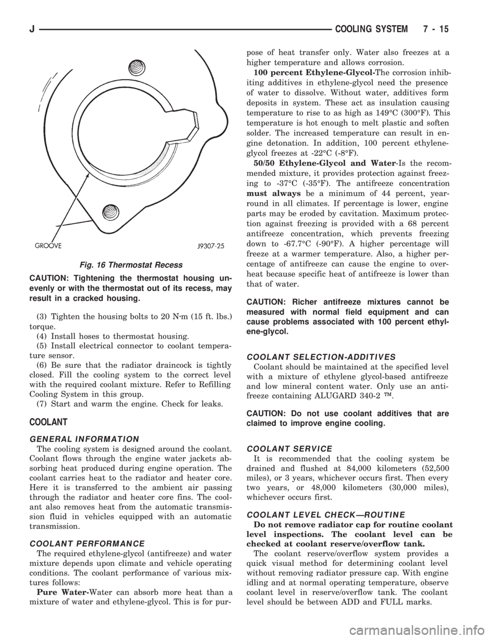
CAUTION: Tightening the thermostat housing un-
evenly or with the thermostat out of its recess, may
result in a cracked housing.
(3) Tighten the housing bolts to 20 Nzm (15 ft. lbs.)
torque.
(4) Install hoses to thermostat housing.
(5) Install electrical connector to coolant tempera-
ture sensor.
(6) Be sure that the radiator draincock is tightly
closed. Fill the cooling system to the correct level
with the required coolant mixture. Refer to Refilling
Cooling System in this group.
(7) Start and warm the engine. Check for leaks.
COOLANT
GENERAL INFORMATION
The cooling system is designed around the coolant.
Coolant flows through the engine water jackets ab-
sorbing heat produced during engine operation. The
coolant carries heat to the radiator and heater core.
Here it is transferred to the ambient air passing
through the radiator and heater core fins. The cool-
ant also removes heat from the automatic transmis-
sion fluid in vehicles equipped with an automatic
transmission.
COOLANT PERFORMANCE
The required ethylene-glycol (antifreeze) and water
mixture depends upon climate and vehicle operating
conditions. The coolant performance of various mix-
tures follows:
Pure Water-Water can absorb more heat than a
mixture of water and ethylene-glycol. This is for pur-pose of heat transfer only. Water also freezes at a
higher temperature and allows corrosion.
100 percent Ethylene-Glycol-The corrosion inhib-
iting additives in ethylene-glycol need the presence
of water to dissolve. Without water, additives form
deposits in system. These act as insulation causing
temperature to rise to as high as 149ÉC (300ÉF). This
temperature is hot enough to melt plastic and soften
solder. The increased temperature can result in en-
gine detonation. In addition, 100 percent ethylene-
glycol freezes at -22ÉC (-8ÉF).
50/50 Ethylene-Glycol and Water-Is the recom-
mended mixture, it provides protection against freez-
ing to -37ÉC (-35ÉF). The antifreeze concentration
must alwaysbe a minimum of 44 percent, year-
round in all climates. If percentage is lower, engine
parts may be eroded by cavitation. Maximum protec-
tion against freezing is provided with a 68 percent
antifreeze concentration, which prevents freezing
down to -67.7ÉC (-90ÉF). A higher percentage will
freeze at a warmer temperature. Also, a higher per-
centage of antifreeze can cause the engine to over-
heat because specific heat of antifreeze is lower than
that of water.
CAUTION: Richer antifreeze mixtures cannot be
measured with normal field equipment and can
cause problems associated with 100 percent ethyl-
ene-glycol.
COOLANT SELECTION-ADDITIVES
Coolant should be maintained at the specified level
with a mixture of ethylene glycol-based antifreeze
and low mineral content water. Only use an anti-
freeze containing ALUGARD 340-2 Ÿ.
CAUTION: Do not use coolant additives that are
claimed to improve engine cooling.
COOLANT SERVICE
It is recommended that the cooling system be
drained and flushed at 84,000 kilometers (52,500
miles), or 3 years, whichever occurs first. Then every
two years, or 48,000 kilometers (30,000 miles),
whichever occurs first.
COOLANT LEVEL CHECKÐROUTINE
Do not remove radiator cap for routine coolant
level inspections. The coolant level can be
checked at coolant reserve/overflow tank.
The coolant reserve/overflow system provides a
quick visual method for determining coolant level
without removing radiator pressure cap. With engine
idling and at normal operating temperature, observe
coolant level in reserve/overflow tank. The coolant
level should be between ADD and FULL marks.
Fig. 16 Thermostat Recess
JCOOLING SYSTEM 7 - 15
Page 252 of 1784

Leakage Test. Do this if it is certain that coolant is
being lost and no leaks can be detected.
²Drops Slowly: Shows a small leak or seepage is oc-
curring. Examine all connections for seepage or
slight leakage with a flashlight. Inspect the radiator,
hoses, gasket edges and heater. Seal any small leak
holes with a Sealer Lubricant or equivalent. Repair
leak holes and reinspect the system with pressure
applied.
²Drops Quickly: Shows that a serious leakage is oc-
curring. Examine the system for serious external
leakage. If no leaks are visible, inspect for internal
leakage. Large radiator leak holes should be repaired
by a reputable radiator repair shop.
INTERNAL LEAKAGE INSPECTION
Remove the oil pan drain plug and drain a small
amount of engine oil. Coolant, being heavier will
drain first, or operate engine to churn oil, then ex-
amine dipstick for water globules. Inspect the trans-
mission dipstick for water globules. Inspect the
transmission fluid cooler for leakage. Operate the en-
gine without the pressure cap on the radiator until
thermostat opens.
Attach a Pressure Tester to the filler neck. If pres-
sure builds up quickly, a leak exists as result of a
faulty cylinder head gasket or crack in the engine.
Repair as necessary.
WARNING: DO NOT ALLOW PRESSURE TO EX-
CEED 124 KPA (18 PSI). TURN THE ENGINE OFF.
TO RELEASE THE PRESSURE, ROCK THE TESTER
FROM SIDE TO SIDE. WHEN REMOVING THE
TESTER, DO NOT TURN THE TESTER MORE THAN
1/2 TURN IF THE SYSTEM IS UNDER PRESSURE.
If there is no immediate pressure increase, pump
the Pressure Tester until the indicated pressure is
within the system range. Vibration of the gauge
pointer indicates compression or combustion leakage
into the cooling system.WARNING: DO NOT DISCONNECT THE SPARK
PLUG WIRES WHILE THE ENGINE IS OPERATING.
CAUTION: Do not operate the engine with a spark
plug shorted for more than a minute. The catalytic
converter may be damaged.
Isolate the compression leak by shorting each
spark plug to the cylinder block. The gauge pointer
should stop or decrease vibration when spark plug
for leaking cylinder is shorted. This happens because
of the absence of combustion pressure.
COMBUSTION LEAKAGE TEST (WITHOUT
PRESSURE TESTER)
DO NOT WASTE reusable coolant. If the solution
is clean, drain the coolant into a clean container for
reuse.
WARNING: DO NOT REMOVE THE CYLINDER
BLOCK DRAIN PLUGS OR LOOSEN THE RADIATOR
DRAINCOCK WITH THE SYSTEM HOT AND UNDER
PRESSURE. SERIOUS BURNS FROM COOLANT
CAN OCCUR.
Drain sufficient coolant to allow for thermostat re-
moval. Refer to Thermostat Replacement. Disconnect
the water pump drive belt.
Disconnect the upper radiator hose from the ther-
mostat housing. Remove the housing and thermostat.
Install the thermostat housing.
Add coolant to the radiator to bring the level to
within 6.3 mm (1/4 in) of the top of the thermostat
housing.
CAUTION: Avoid overheating. Do not operate the
engine for an excessive period of time. Open the
draincock immediately after the test to eliminate
boil over of coolant.
Start the engine and accelerate rapidly three times
(to approximately 3000 rpm) while observing the
coolant. If internal engine combustion gases are leak-
ing into the cooling system, bubbles will appear in
the coolant. If bubbles do not appear, there is no in-
ternal combustion gas leakage.
COOLANT RESERVE/OVERFLOW SYSTEM
The system works along with the radiator pressure
cap. This is done by using thermal expansion and
contraction of the coolant to keep the coolant free of
trapped air. It provides:
²A volume for coolant expansion and contraction.
²A convenient and safe method for checking/adjust-
ing coolant level at atmospheric pressure. This is
done without removing the radiator pressure cap.
²Some reserve coolant to cover minor leaks and
evaporation or boiling losses.
Fig. 20 Pressurizing SystemÐTypical
JCOOLING SYSTEM 7 - 19
Page 255 of 1784
RADIATORS
GENERAL INFORMATION
All radiators are down flow types except XJ models
with 4.0L engines. Radiators in XJ models equipped
with the 4.0L six-cylinder engine, are the cross flow
type. Plastic tanks are used on all radiators.
CAUTION: Plastic tanks, while stronger than brass,
are subject to damage by impact, such as
wrenches.
If plastic tank has been damaged, plastic tank
and/or O-rings are available for service repair. Tank
replacement should be done by qualified personal
with proper equipment.
RADIATOR COOLANT FLOW CHECK
The following procedure will determine if coolant is
flowing through the cooling system.
If engine is cold, idle engine until normal operating
temperature is reached. Then feel the upper radiator
hose. If hose is hot, the thermostat is open and water
is circulating through cooling system.
RADIATOR REMOVAL/INSTALLATION
WARNING: DO NOT REMOVE THE CYLINDER
BLOCK DRAIN PLUGS, RADIATOR CAP, OR
LOOSEN THE RADIATOR DRAINCOCK WITH THE
SYSTEM HOT AND PRESSURIZED. SERIOUS
BURNS FROM THE COOLANT CAN OCCUR.
DO NOT WASTE reusable coolant. If solution is
clean, drain coolant into a clean container for reuse.
WARNING: CONSTANT TENSION HOSE CLAMPS
ARE USED ON MOST COOLING SYSTEM HOSES.
WHEN REMOVING OR INSTALLING, USE ONLY
TOOLS DESIGNED FOR SERVICING THIS TYPE OF
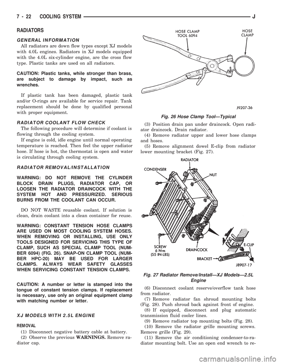
CLAMP, SUCH AS SPECIAL CLAMP TOOL (NUM-
BER 6094) (FIG. 26). SNAP-ON CLAMP TOOL (NUM-
BER HPC-20) MAY BE USED FOR LARGER
CLAMPS. ALWAYS WEAR SAFETY GLASSES
WHEN SERVICING CONSTANT TENSION CLAMPS.
CAUTION: A number or letter is stamped into the
tongue of constant tension clamps. If replacement
is necessary, use only an original equipment clamp
with matching number or letter.
XJ MODELS WITH 2.5L ENGINE
REMOVAL
(1) Disconnect negative battery cable at battery.
(2) Observe the previousWARNINGS.Remove ra-
diator cap.(3) Position drain pan under draincock. Open radi-
ator draincock. Drain radiator.
(4) Remove radiator upper and lower hose clamps
and hoses.
(5) Remove alignment dowel E-clip from radiator
lower mounting bracket (Fig. 27).
(6) Disconnect coolant reserve/overflow tank hose
from radiator.
(7) Remove radiator fan shroud mounting bolts
(Fig. 28). Push shroud back against front of engine.
(8) If equipped, disconnect and plug automatic
transmission fluid cooler lines.
(9) Remove radiator top mounting bolts (Fig. 28).
(10) Remove the radiator grille mounting screws.
Remove grille (Fig. 29).
(11) Remove the air conditioning condenser-to-ra-
diator mounting bolt. Use an open end wrench to re-
Fig. 26 Hose Clamp ToolÐTypical
Fig. 27 Radiator Remove/InstallÐXJ ModelsÐ2.5L
Engine
7 - 22 COOLING SYSTEMJ
Page 256 of 1784
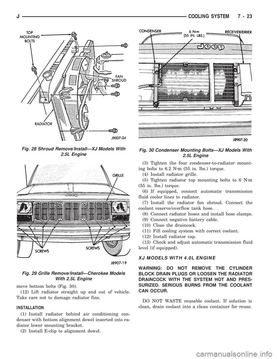
move bottom bolts (Fig. 30).
(12) Lift radiator straight up and out of vehicle.
Take care not to damage radiator fins.
INSTALLATION
(1) Install radiator behind air conditioning con-
denser with bottom alignment dowel inserted into ra-
diator lower mounting bracket.
(2) Install E-clip to alignment dowel.(3) Tighten the four condenser-to-radiator mount-
ing bolts to 6.2 Nzm (55 in. lbs.) torque.
(4) Install radiator grille.
(5) Tighten radiator top mounting bolts to 6 Nzm
(55 in. lbs.) torque.
(6) If equipped, connect automatic transmission
fluid cooler lines to radiator.
(7) Install the radiator fan shroud. Connect the
coolant reserve/overflow tank hose.
(8) Connect radiator hoses and install hose clamps.
(9) Connect negative battery cable.
(10) Close the draincock.
(11) Fill cooling system with correct coolant.
(12) Install radiator cap.
(13) Check and adjust automatic transmission fluid
level (if equipped).
XJ MODELS WITH 4.0L ENGINE
WARNING: DO NOT REMOVE THE CYLINDER
BLOCK DRAIN PLUGS OR LOOSEN THE RADIATOR
DRAINCOCK WITH THE SYSTEM HOT AND PRES-
SURIZED. SERIOUS BURNS FROM THE COOLANT
CAN OCCUR.
DO NOT WASTE reusable coolant. If solution is
clean, drain coolant into a clean container for reuse.
Fig. 28 Shroud Remove/InstallÐXJ Models With
2.5L Engine
Fig. 29 Grille Remove/InstallÐCherokee Models
With 2.5L Engine
Fig. 30 Condenser Mounting BoltsÐXJ Models With
2.5L Engine
JCOOLING SYSTEM 7 - 23