1994 JEEP CHEROKEE boot
[x] Cancel search: bootPage 1115 of 1784
(6) Remove slave cylinder from clutch housing.
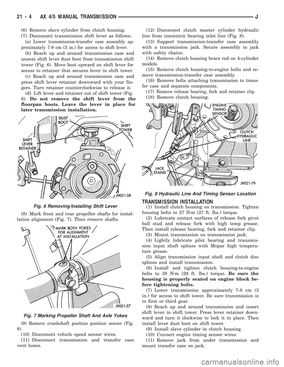
(7) Disconnect transmission shift lever as follows:
(a) Lower transmission-transfer case assembly ap-
proximately 7-8 cm (3 in.) for access to shift lever.
(b) Reach up and around transmission case and
unseat shift lever dust boot from transmission shift
tower (Fig. 6). Move boot upward on shift lever for
access to retainer that secures lever in shift tower.
(c) Reach up and around transmission case and
press shift lever retainer downward with your fin-
gers. Turn retainer counterclockwise to release it.
(d) Lift lever and retainer out of shift tower (Fig.
6).Do not remove the shift lever from the
floorpan boots. Leave the lever in place for
later transmission installation.
(8) Mark front and rear propeller shafts for instal-
lation alignment (Fig. 7). Then remove shafts.
(9) Remove crankshaft position position sensor (Fig.
8).
(10) Disconnect vehicle speed sensor wires.
(11) Disconnect transmission and transfer case
vent hoses.(12) Disconnect clutch master cylinder hydraulic
line from concentric bearing inlet line (Fig. 8).
(13) Support transmission-transfer case assembly
with a transmission jack. Secure assembly to jack
with safety chains.
(14) Remove clutch housing brace rod on 4-cylinder
models.
(15) Remove clutch housing-to-engine bolts and re-
move transmission-transfer case assembly.
(16) Remove bolts attaching transmission to trans-
fer case and separate components.
(17) Remove release bearing, fork and retainer clip.
(18) Remove clutch housing.
TRANSMISSION INSTALLATION
(1) Install clutch housing on transmission. Tighten
housing bolts to 37 Nzm (27 ft. lbs.) torque.
(2) Lubricate contact surfaces of release fork pivot
ball stud and release fork with high temp grease.
Then install release bearing, fork and retainer clip.
(3) Mount transmission on transmission jack.
(4) Lightly lubricate pilot bearing and transmis-
sion input shaft splines with Mopar high tempera-
ture grease.
(5) Align transmission input shaft and clutch disc
splines and install transmission.
(6) Install and tighten clutch housing-to-engine
bolts to 38 Nzm (28 ft. lbs.) torque.Be sure the
housing is properly seated on engine block be-
fore tightening bolts.
(7) Lower transmission approximately 7-8 cm (3
in.) for access to shift tower. Be sure transmission is
in first or third gear.
(8) Reach up and around transmission and insert
shift lever in shift tower. Press lever retainer down-
ward and turn it clockwise to lock it in place. Then
install lever dust boot on shift tower.
(9) Install slave cylinder in clutch housing.
(10) Connect engine timing sensor wires.
(11) Remove jack from under transmission and
mount transfer case on jack.Fig. 6 Removing/Installing Shift Lever
Fig. 7 Marking Propeller Shaft And Axle Yokes
Fig. 8 Hydraulic Line And Timing Sensor Location
21 - 4 AX 4/5 MANUAL TRANSMISSIONJ
Page 1146 of 1784
(9) Reach up and around transmission case and
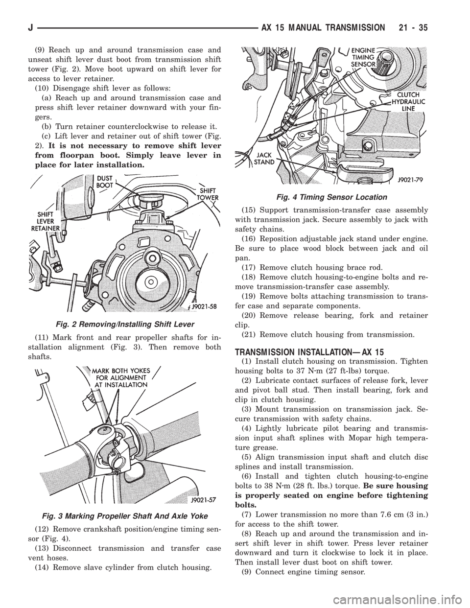
unseat shift lever dust boot from transmission shift
tower (Fig. 2). Move boot upward on shift lever for
access to lever retainer.
(10) Disengage shift lever as follows:
(a) Reach up and around transmission case and
press shift lever retainer downward with your fin-
gers.
(b) Turn retainer counterclockwise to release it.
(c) Lift lever and retainer out of shift tower (Fig.
2).It is not necessary to remove shift lever
from floorpan boot. Simply leave lever in
place for later installation.
(11) Mark front and rear propeller shafts for in-
stallation alignment (Fig. 3). Then remove both
shafts.
(12) Remove crankshaft position/engine timing sen-
sor (Fig. 4).
(13) Disconnect transmission and transfer case
vent hoses.
(14) Remove slave cylinder from clutch housing.(15) Support transmission-transfer case assembly
with transmission jack. Secure assembly to jack with
safety chains.
(16) Reposition adjustable jack stand under engine.
Be sure to place wood block between jack and oil
pan.
(17) Remove clutch housing brace rod.
(18) Remove clutch housing-to-engine bolts and re-
move transmission-transfer case assembly.
(19) Remove bolts attaching transmission to trans-
fer case and separate components.
(20) Remove release bearing, fork and retainer
clip.
(21) Remove clutch housing from transmission.
TRANSMISSION INSTALLATIONÐAX 15
(1) Install clutch housing on transmission. Tighten
housing bolts to 37 Nzm (27 ft-lbs) torque.
(2) Lubricate contact surfaces of release fork, lever
and pivot ball stud. Then install bearing, fork and
clip in clutch housing.
(3) Mount transmission on transmission jack. Se-
cure transmission with safety chains.
(4) Lightly lubricate pilot bearing and transmis-
sion input shaft splines with Mopar high tempera-
ture grease.
(5) Align transmission input shaft and clutch disc
splines and install transmission.
(6) Install and tighten clutch housing-to-engine
bolts to 38 Nzm (28 ft. lbs.) torque.Be sure housing
is properly seated on engine before tightening
bolts.
(7) Lower transmission no more than 7.6 cm (3 in.)
for access to the shift tower.
(8) Reach up and around the transmission and in-
sert shift lever in shift tower. Press lever retainer
downward and turn it clockwise to lock it in place.
Then install lever dust boot on shift tower.
(9) Connect engine timing sensor.
Fig. 2 Removing/Installing Shift Lever
Fig. 3 Marking Propeller Shaft And Axle Yoke
Fig. 4 Timing Sensor Location
JAX 15 MANUAL TRANSMISSION 21 - 35
Page 1386 of 1784
SHIFT LINKAGE ADJUSTMENT
LINKAGE ADJUSTMENTÐYJ
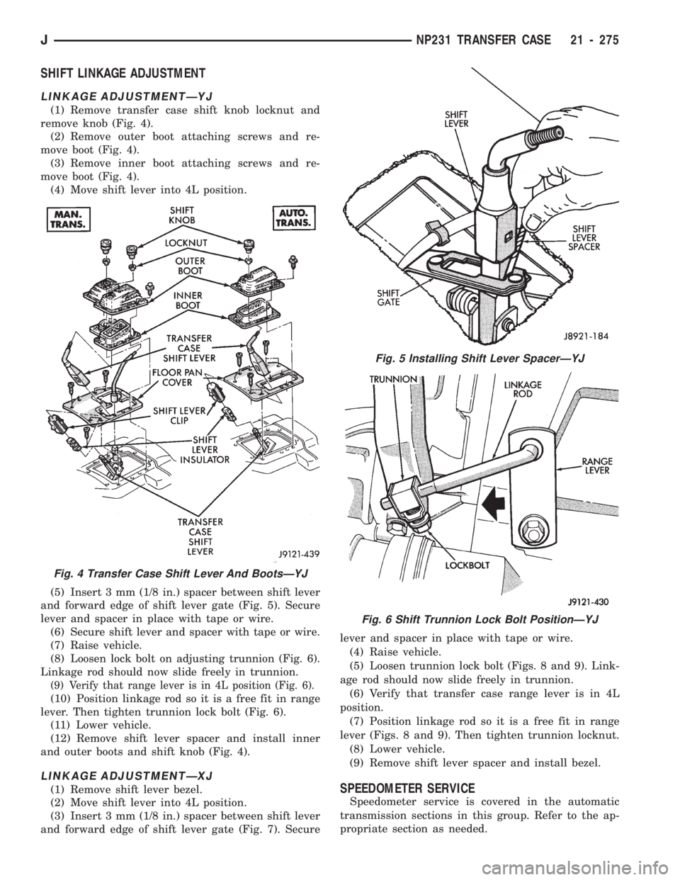
(1) Remove transfer case shift knob locknut and
remove knob (Fig. 4).
(2) Remove outer boot attaching screws and re-
move boot (Fig. 4).
(3) Remove inner boot attaching screws and re-
move boot (Fig. 4).
(4) Move shift lever into 4L position.
(5) Insert 3 mm (1/8 in.) spacer between shift lever
and forward edge of shift lever gate (Fig. 5). Secure
lever and spacer in place with tape or wire.
(6) Secure shift lever and spacer with tape or wire.
(7) Raise vehicle.
(8) Loosen lock bolt on adjusting trunnion (Fig. 6).
Linkage rod should now slide freely in trunnion.
(9) Verify that range lever is in 4L position (Fig. 6).
(10) Position linkage rod so it is a free fit in range
lever. Then tighten trunnion lock bolt (Fig. 6).
(11) Lower vehicle.
(12) Remove shift lever spacer and install inner
and outer boots and shift knob (Fig. 4).
LINKAGE ADJUSTMENTÐXJ
(1) Remove shift lever bezel.
(2) Move shift lever into 4L position.
(3) Insert 3 mm (1/8 in.) spacer between shift lever
and forward edge of shift lever gate (Fig. 7). Securelever and spacer in place with tape or wire.
(4) Raise vehicle.
(5) Loosen trunnion lock bolt (Figs. 8 and 9). Link-
age rod should now slide freely in trunnion.
(6) Verify that transfer case range lever is in 4L
position.
(7) Position linkage rod so it is a free fit in range
lever (Figs. 8 and 9). Then tighten trunnion locknut.
(8) Lower vehicle.
(9) Remove shift lever spacer and install bezel.SPEEDOMETER SERVICE
Speedometer service is covered in the automatic
transmission sections in this group. Refer to the ap-
propriate section as needed.
Fig. 4 Transfer Case Shift Lever And BootsÐYJ
Fig. 5 Installing Shift Lever SpacerÐYJ
Fig. 6 Shift Trunnion Lock Bolt PositionÐYJ
JNP231 TRANSFER CASE 21 - 275
Page 1495 of 1784
DOOR REMOVAL/INSTALLATION
REMOVAL
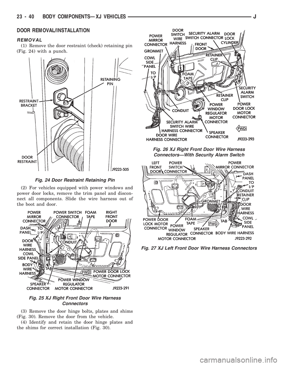
(1) Remove the door restraint (check) retaining pin
(Fig. 24) with a punch.
(2) For vehicles equipped with power windows and
power door locks, remove the trim panel and discon-
nect all components. Slide the wire harness out of
the boot and door.
(3) Remove the door hinge bolts, plates and shims
(Fig. 30). Remove the door from the vehicle.
(4) Identify and retain the door hinge plates and
the shims for correct installation (Fig. 30).
Fig. 24 Door Restraint Retaining Pin
Fig. 25 XJ Right Front Door Wire Harness
Connectors
Fig. 26 XJ Right Front Door Wire Harness
ConnectorsÐWith Security Alarm Switch
Fig. 27 XJ Left Front Door Wire Harness Connectors
23 - 40 BODY COMPONENTSÐXJ VEHICLESJ
Page 1584 of 1784
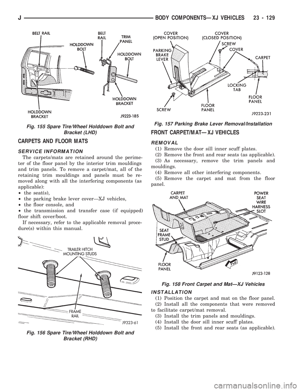
CARPETS AND FLOOR MATS
SERVICE INFORMATION
The carpets/mats are retained around the perime-
ter of the floor panel by the interior trim mouldings
and trim panels. To remove a carpet/mat, all of the
retaining trim mouldings and panels must be re-
moved along with all the interfering components (as
applicable):
²the seat(s),
²the parking brake lever coverÐXJ vehicles,
²the floor console, and
²the transmission and transfer case (if equipped)
floor shift cover/boot.
If necessary, refer to the applicable removal proce-
dure(s) within this manual.
FRONT CARPET/MATÐXJ VEHICLES
REMOVAL
(1) Remove the door sill inner scuff plates.
(2) Remove the front and rear seats (as applicable).
(3) As necessary, remove the trim panels and
mouldings.
(4) Remove all other interfering components.
(5) Remove the carpet and mat from the floor
panel.
INSTALLATION
(1) Position the carpet and mat on the floor panel.
(2) Install all the components that were removed
to facilitate carpet/mat removal.
(3) Install the trim panels and mouldings.
(4) Install the door sill inner scuff plates.
(5) Install the front and rear seats (as applicable).
Fig. 156 Spare Tire/Wheel Holddown Bolt and
Bracket (RHD)
Fig. 155 Spare Tire/Wheel Holddown Bolt and
Bracket (LHD)Fig. 157 Parking Brake Lever Removal/Installation
Fig. 158 Front Carpet and MatÐXJ Vehicles
JBODY COMPONENTSÐXJ VEHICLES 23 - 129
Page 1653 of 1784
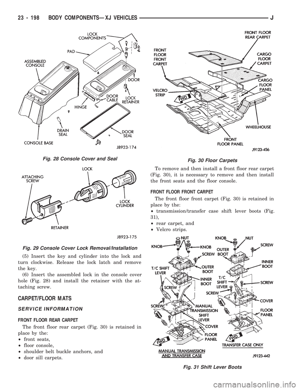
(5) Insert the key and cylinder into the lock and
turn clockwise. Release the lock latch and remove
the key.
(6) Insert the assembled lock in the console cover
hole (Fig. 28) and install the retainer with the at-
taching screw.
CARPET/FLOOR MATS
SERVICE INFORMATION
FRONT FLOOR REAR CARPET
The front floor rear carpet (Fig. 30) is retained in
place by the:
²front seats,
²floor console,
²shoulder belt buckle anchors, and
²door sill carpets.To remove and then install a front floor rear carpet
(Fig. 30), it is necessary to remove and then install
the front seats and the floor console.
FRONT FLOOR FRONT CARPET
The front floor front carpet (Fig. 30) is retained in
place by the:
²transmission/transfer case shift lever boots (Fig.
31),
²rear carpet, and
²Velcro strips.
Fig. 28 Console Cover and Seal
Fig. 29 Console Cover Lock Removal/Installation
Fig. 30 Floor Carpets
Fig. 31 Shift Lever Boots
23 - 198 BODY COMPONENTSÐXJ VEHICLESJ
Page 1654 of 1784
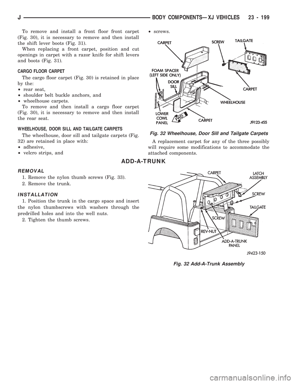
To remove and install a front floor front carpet
(Fig. 30), it is necessary to remove and then install
the shift lever boots (Fig. 31).
When replacing a front carpet, position and cut
openings in carpet with a razor knife for shift levers
and boots (Fig. 31).
CARGO FLOOR CARPET
The cargo floor carpet (Fig. 30) is retained in place
by the:
²rear seat,
²shoulder belt buckle anchors, and
²wheelhouse carpets.
To remove and then install a cargo floor carpet
(Fig. 30), it is necessary to remove and then install
the rear seat.
WHEELHOUSE, DOOR SILL AND TAILGATE CARPETS
The wheelhouse, door sill and tailgate carpets (Fig.
32) are retained in place with:
²adhesive,
²velcro strips, and²screws.
A replacement carpet for any of the three possibly
will require some modifications to accommodate the
attached components.
ADD-A-TRUNK
REMOVAL
1. Remove the nylon thumb screws (Fig. 33).
2. Remove the trunk.
INSTALLATION
1. Position the trunk in the cargo space and insert
the nylon thumbscrews with washers through the
predrilled holes and into the well nuts.
2. Tighten the thumb screws.
Fig. 32 Wheelhouse, Door Sill and Tailgate Carpets
Fig. 32 Add-A-Trunk Assembly
JBODY COMPONENTSÐXJ VEHICLES 23 - 199
Page 1692 of 1784
(4) Connect the heater hoses to the heater core.
(5) Fill the cooling system.
HEATER CORE HOUSING REPLACEMENT
(1) Remove the evaporator/blower housing.
(2) Remove the heater core.
(3) Remove the defroster duct.
(4) Disconnect the vacuum hoses from the heater
core housing vacuum motors.
(5) Remove the heater housing retaining nuts in
the engine compartment. Remove the heater core
housing.
(6) Transfer the vacuum motors, etc. to the re-
placement housing.
To install the heater core housing, reverse the re-
moval procedure.
DEFROSTER DUCT REPLACEMENT
REMOVAL
(1) Disconnect negative cable from battery.
(2) If equipped with center console remove the con-
sole as follows:
(a) MANUAL TRANSMISSIONÐRemove shift
knob, boot and bezel.
(b) AUTOMATIC TRANSMISSIONÐRemove
shift handle by pulling up. Remove the shift bezel.
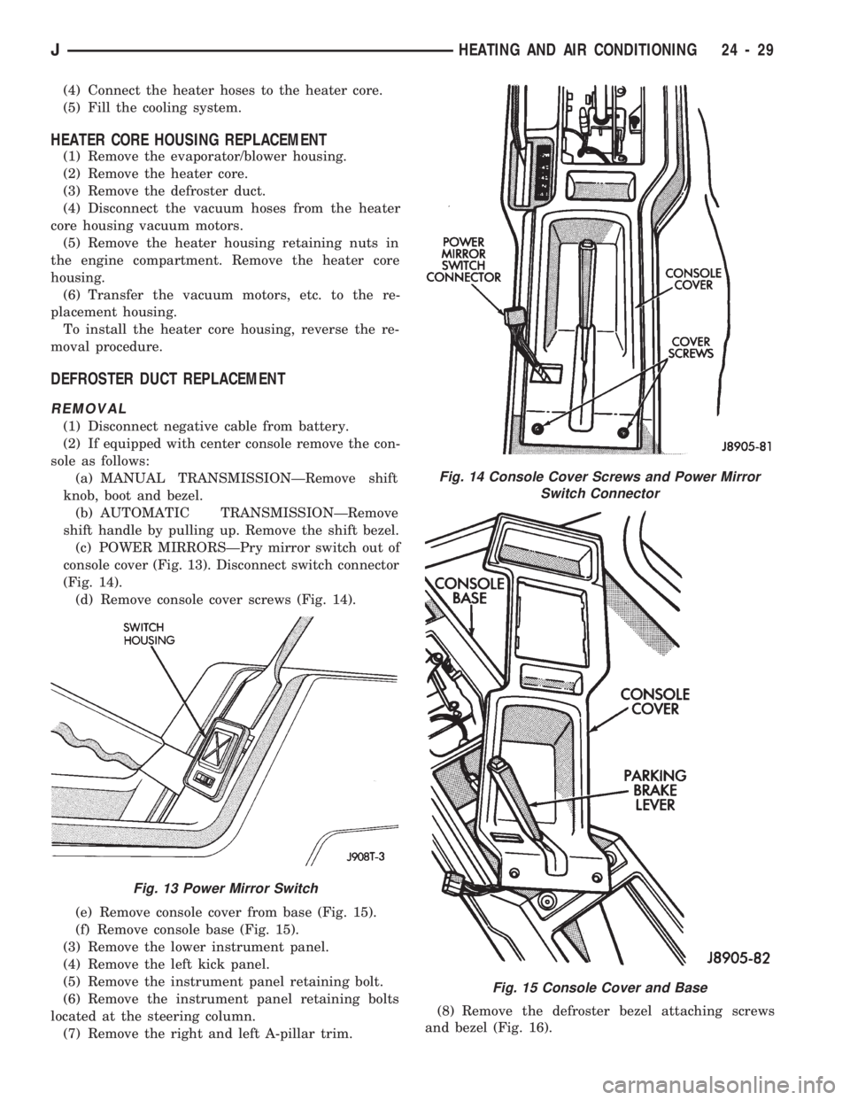
(c) POWER MIRRORSÐPry mirror switch out of
console cover (Fig. 13). Disconnect switch connector
(Fig. 14).
(d) Remove console cover screws (Fig. 14).
(e) Remove console cover from base (Fig. 15).
(f) Remove console base (Fig. 15).
(3) Remove the lower instrument panel.
(4) Remove the left kick panel.
(5) Remove the instrument panel retaining bolt.
(6) Remove the instrument panel retaining bolts
located at the steering column.
(7) Remove the right and left A-pillar trim.(8) Remove the defroster bezel attaching screws
and bezel (Fig. 16).
Fig. 13 Power Mirror Switch
Fig. 14 Console Cover Screws and Power Mirror
Switch Connector
Fig. 15 Console Cover and Base
JHEATING AND AIR CONDITIONING 24 - 29