1994 JEEP CHEROKEE check engine
[x] Cancel search: check enginePage 1680 of 1784
COMPRESSOR OVERHAUL
INDEX
page page
Compressor............................. 17
Compressor Isolation...................... 17
Description............................. 17Magnetic Clutch......................... 18
Purging Compressor of Air................. 17
DESCRIPTION
The A/C system uses a Sanden compressor. This
compressor is a 7 piston design. Designated the SD-
709, the compressor is mounted on the front right
side of the engine and is driven by a serpentine belt.
System lubrication is provided by 135cc615cc (4.6
cu. in.60.5 cu. in.) of 500 viscosity refrigerant oil.
The clutch used on the compressor consists of 3 ba-
sic components: the pulley, front plate and the field
coil. The pulley and field coil are attached to the
front head of the compressor with tapered snap rings.
The hub is keyed to the compressor shaft and is re-
tained on the shaft with a self-locking nut. Special
service tools are required to remove and install the
clutch plate on the compressor shaft.
COMPRESSOR ISOLATION
It is not necessary to discharge the system for com-
pressor removal. The compressor can be isolated from
the remainder of the system and eliminate the need
for recharging when performing compressor service.
(1) Connect pressure gauge and manifold.
(2) Close both gauge hand valves.
(3) Mid-position both service valves.
WARNING: USE EXTREME CAUTION WHEN THE
ENGINE IS OPERATING. DO NOT STAND IN A DI-
RECT LINE WITH THE FAN. DO NOT PUT YOUR
HANDS NEAR THE PULLEYS, BELTS OR FAN. DO
NOT WEAR LOOSE CLOTHING.
(4) Start the engine and operate the air condition-
ing system.
(5) Turn the suction service valve slowly clockwise
toward the front seated position.
(6) When pressure drops to zero, stop the engine
and compressor and quickly finish front-seating the
suction service valve.
(7) Front-seat the discharge service valve.
(8) Loosen the oil level check plug slowly to re-
lease any internal pressure in the compressor.
The compressor is now isolated from the remainder
of the system.
The service valves can be removed from the com-
pressor.
PURGING COMPRESSOR OF AIR
The compressor must be purged of air whenever it
has been isolated for an oil level check or other ser-
vice procedures without discharging the entire sys-
tem.
(1) Cap the service gauge ports on both of the ser-
vice valves.
(2) Back-seat the suction service valve to allow the
system refrigerant to enter the compressor.
(3) Place the discharge service valve in the mid-po-
sition or cracked-position.
(4) Loosen the discharge service valve gauge port
cap to permit the refrigerant to force any air out of
the compressor.
(5) Back-seat the discharge service valve and
tighten the gauge port cap.
(6) The compressor is now ready for service.
COMPRESSOR
REMOVAL
(1) Isolate the compressor.
(2) Disconnect negative cable from battery.
(3) Disconnect the clutch lead wire.
(4) Remove the discharge and inlet (suction) ser-
vice valves from the compressor. Plug or tape all the
openings.
(5) Remove the serpentine drive belt (refer to
Group 7, Cooling System for the proper procedure).
(6) Remove the bolts and lift the compressor from
the mounting bracket (Figs. 1 and 2).
INSTALLATION
If a replacement compressor is being installed;
check the oil level. Add or subtract oil as neces-
sary and install the magnetic clutch on the com-
pressor.
(1) If the mounting bracket was removed, install
the bracket to the block. Tighten the mounting bolts
to 27 NIm (20 ft. lbs.) torque.
(2) Install the compressor on the mounting
bracket. Tighten the bolts to 27 NIm (20 ft. lbs.)
torque.
(3) Install the serpentine drive belt (refer to Group
7, Cooling System for the proper procedure).
(4) Tighten the serpentine drive belt to the speci-
fied tension.
²New belt tensionÐ800-900 N (180-200 lb-f).
JHEATING AND AIR CONDITIONING 24 - 17
Page 1685 of 1784
CLIMATE CONTROL SYSTEMÐXJ VEHICLES
INDEX
page page
A/C Recirculating Air Door Vacuum Motor
Replacement.......................... 31
Blower Motor Resistors Replacement......... 35
Blower Motor/Fan Replacement.............. 26
CondenserÐ4.0L Engines.................. 32
Condenser/Receiver DrierÐ2.5L Engines....... 31
Defroster Duct Replacement................ 29
Description............................. 22
Evaporator Coil.......................... 34
Evaporator/Blower Housing................. 33Expansion (H) Valve...................... 35
Heater and A/C Control Panel Replacement.... 26
Heater Control Cable Replacement........... 30
Heater Core............................ 28
Heater Core Housing Replacement........... 29
Heater/Defroster/Instrument Panel Outlet Door
Vacuum Motor Replacement............... 30
Receiver DrierÐ4.0L Engines............... 32
Temperature Control Thermostat............. 35
DESCRIPTION
The Climate Control System combines air condi-
tioning, heating and ventilating capabilities for vehi-
cles equipped with air conditioning. Vehicles without
air conditioning perform heating and ventilating
functions without the air conditioning evaporator.
Both systems consist basically of 2 parts:
²Blower and Air Inlet Assembly
²Heater Core and Air Distribution Assembly
These assemblies, initially installed as a single
unit, may be removed separately from under the in-
strument panel as required for service.
HEATER SYSTEM
The heater system is a blend air type. Outside air
is heated and then blended in varying amounts with
cooler outside air to obtain the desired discharge
temperature. A heater coolant valve provides full
flow to the heater core for all heating modes. The
heater coolant valve remains closed for the ventila-
tion mode, allowing discharge air to approach the
outside ambient air temperature.
AIR CONDITIONING SYSTEM
The air conditioning system has an evaporator to
cool and dehumidify the incoming outside air prior to
blending with the heated air. The evaporator is in
operation during the A/C mode and also in the de-
frost mode for defogging purposes. The evaporator is
not in operation at ambient temperatures below ap-
proximately -1ÉC (30ÉF). To maintain minimum evap-
orator temperature, a fixed thermostat setting switch
cycles the compressor clutch. The blower is operatingthe heater or air conditioning systems, except the
OFF mode. In this mode (OFF) the blower and the
outside air are shut off.
The cooling unit is mounted on the dash panel and
the cooled air is discharged from the instrument
panel registers. The registers are adjusted to provide
general or localized cooling.
SIGHT GLASS
The sight glass is located on top of the receiver/
drier. The sight glass provides a visual check of the
system refrigerant level. A continuous stream of bub-
bles will appear in the sight glass when the system
charge is low. Bubbles will not appear when the sys-
tem is fully charged.
LOW PRESSURE SWITCH
The low pressure switch disengages the magnetic
clutch if the pressure in the system drops below 193
kPa (28 psi). This will occur with a loss in refriger-
ant or with cold ambient temperature.
HEATER VALVE
The heater valve regulates coolant flow to the
heater core. It requires vacuum to shut off flow to
the heater core.
These vehicles are equipped with a bypass-type
heater water valve. When the heater valve is closed,
coolant flow to the heater core is bypassed back to
the engine. When the heater valve is open, coolant is
directed through the heater core and back to the en-
gine.
24 - 22 HEATING AND AIR CONDITIONINGJ
Page 1703 of 1784
HEATER CORE AND HOUSING
REMOVAL
WARNING: HOT ENGINE COOLANT CAN CAUSE
SEVERE BURNS. DO NOT OPEN THE RADIATOR
DRAIN COCK WHEN THE COOLING SYSTEM IS
HOT AND PRESSURIZED. ALLOW THE COOLANT
TO DECREASE TO ROOM TEMPERATURE BEFORE
STARTING REPAIR OPERATIONS.
(1) Drain approximately 1.9 liters (2 qts) of coolant
from the radiator. Drain the coolant into a clean con-
tainer.
(2) Disconnect the heater hoses.
(3) Disconnect the vent door cables.
(4) Disconnect the blower motor wire.
(5) Disconnect the defroster duct.
(6) Remove the nuts that attach the heater hous-
ing studs to the engine compartment side of the dash
panel.
(7) Remove the heater housing assembly by tilting
it downward, to disengage it from the defroster duct.
Pull it rearward and out from under the instrument
panel.
(8) Remove the heater hosing cover from the hous-
ing.
(9) Remove the heater core from the housing.
INSTALLATION
(1) Install the heater core in the housing and in-
stall the cover on the housing.
(2) Position the heater housing on the dash panel.
Be sure the housing studs all extend through the
dash panel.
(3) Install the seals on the heater core outlet and
inlet tubes and over the blower motor housing.
(4) Install the attaching nuts on the housing studs.
CAUTION: DO NOT over tighten the attaching nuts.
The housing could become distorted causing air
leaks and improper heater door operation. Tighten
the nuts alternately and evenly until 2 stud threads
are visible beyond each nut.
(5) Connect the defroster duct to the housing.
(6) Connect the blower motor wire.
(7) Connect the vent door control cables.
(8) Connect the heater hoses.
(9) Fill and bleed the cooling system.
(10) Check system operation.
BLOWER MOTOR (HEATING)
REMOVAL
(1) Remove the heater housing.
(2) Remove the blower motor-to-heater housing at-
taching screws/nuts.
(3) Remove the blower motor from the housing.
INSTALLATION
(1) Position the blower motor into the housing.
(2) Install and tighten the blower motor-to-heater
housing attaching screws/nuts.
(3) Install the heater housing.
(4) Check blower motor and heater operation.
DEFROSTER NOZZLE AND DUCT
REMOVAL
WARNING: HOT ENGINE COOLANT CAN CAUSE
SEVERE BURNS. DO NOT OPEN THE RADIATOR
DRAIN COCK WHEN THE COOLING SYSTEM IS
HOT AND PRESSURIZED. ALLOW THE COOLANT
TO DECREASE TO ROOM TEMPERATURE BEFORE
STARTING REPAIR OPERATIONS.
(1) Drain approximately 1.9 liters (2 qts) of coolant
from the radiator. Drain the coolant into a clean con-
tainer.
(2) Disconnect the heater hoses.
(3) Remove the nuts attaching the heater housing
studs to the engine compartment side of the dash
panel.
(4) Disconnect the speedometer cable.
(5) Remove the glove box.
(6) Tilt the heater housing back and pull it rear-
ward and out from under the instrument panel.
(7) Disconnect the vent control cables.
(8) Remove the fresh air intake grille from the
cowl.
(9) Remove the fresh air intake duct.
(10) Lower the windshield.
(11) Remove the defroster nozzle attaching screws
and remove the nozzle and duct.
INSTALLATION
(1) Install the defroster nozzle and duct.
(2) Raise and secure the windshield.
(3) Install the fresh air intake duct.
(4) Install the fresh air intake grille on the cowl.
(5) Install the vent cables.
(6) Position the heater housing on the dash panel.
Be sure all the housing studs extend through the
dash panel.
(7) Install the seals on the blower motor and the
heater core inlet and outlet tubes.
(8) Install the attaching nuts on the housing studs.
CAUTION: DO NOT over tighten the attaching nuts.
The housing could become distorted causing air
leaks and improper heater door operation. Tighten
the nuts alternately and evenly until 2 stud threads
are visible beyond each nut.
(9) Install the glove box.
(10) Connect the speedometer cable.
(11) Connect the heater hoses.
24 - 40 HEATING AND AIR CONDITIONINGJ
Page 1704 of 1784
(12) Fill and bleed the cooling system.
FRESH AIR DOOR VACUUM MOTOR
REMOVAL
(1) Remove the glove box and assist handle.
(2) Disconnect the vacuum hose from the motor.
(3) Remove the motor lever retaining clip.
(4) Remove the motor attaching nuts and remove
the motor from the fresh air duct.
INSTALLATION
(1) Position the motor on the fresh air duct and in-
stall the motor attaching nuts.
(2) Align the motor lever with the air door lever
and install the lever retaining clip.
(3) Connect the vacuum hose to the motor.
(4) Install the glove box and assist handle.
FRESH AIR INTAKE DUCT
REMOVAL
WARNING: HOT ENGINE COOLANT CAN CAUSE
SEVERE BURNS. DO NOT OPEN THE RADIATOR
DRAIN COCK WHEN THE COOLING SYSTEM IS
HOT AND PRESSURIZED. ALLOW THE COOLANT
TO DECREASE TO ROOM TEMPERATURE BEFORE
STARTING REPAIR OPERATIONS.
(1) Drain approximately 1.9 liters (2 qts) of coolant
from the radiator. Drain the coolant into a clean con-
tainer.
(2) Disconnect the heater hoses.
(3) Remove the nuts attaching the heater housing
studs to the dash panel from inside the engine com-
partment.
(4) Disconnect the speedometer cable.
(5) Remove the glove box and assist handle.
(6) Tilt the heater housing back and pull it rear-
ward and out from under the instrument panel.
(7) Disconnect the vent cables.
(8) Remove the fresh air intake grille from the
cowl.
(9) Remove the fresh air intake duct.
INSTALLATION
(1) Install the fresh air intake duct.
(2) Install the defroster nozzle and duct.
(3) Raise and secure the windshield.
(4) Install the fresh air grille on the cowl.
(5) Install the vent cables.
(6) Position the heater housing on the dash panel.
Be sure all the housing studs extend through the
dash panel.
(7) Install the seals on the blower motor and
heater core inlet and outlet tubes.
(8) Install the attaching nuts on the heater hous-
ing studs.CAUTION: DO NOT over tighten the attaching nuts.
The housing could become distorted causing air
leaks and improper heater door operation. Tighten
the nuts alternately and evenly until 2 stud threads
are visible beyond each nut.
(9) Install the glove box and assist handle.
(10) Connect the speedometer cable.
(11) Connect the heater hoses.
(12) Fill and bleed the cooling system.
DESCRIPTION (AIR CONDITIONING)
The evaporator, blower fan and motor, thermostat,
expansion valve, capillary tube, air outlets and sys-
tem controls are located in the evaporator housing.
The evaporator housing is mounted under the instru-
ment panel. The compressor, condenser, receiver-
dryer and refrigerant lines are located in the engine
compartment.
A rotary-type compressor with magnetic clutch op-
erated drive pulley is used for all vehicles equipped
with air conditioning.
SIGHT GLASS
A sight glass is located on the top of the receiver-
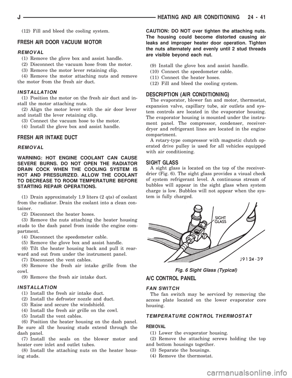
drier (Fig. 6). The sight glass provides a visual check
of system refrigerant level. A continuous stream of
bubbles will appear in the sight glass when system
charge is low. Bubbles will not appear when the sys-
tem is fully charged.
A/C CONTROL PANEL
FAN SWITCH
The fan switch may be serviced by removing the
access plate located on the lower evaporator core
housing.
TEMPERATURE CONTROL THERMOSTAT
REMOVAL
(1) Lower the evaporator housing.
(2) Remove the attaching screws holding the top
and bottom housings together.
(3) Separate the housings.
(4) Remove the thermostat.
Fig. 6 Sight Glass (Typical)
JHEATING AND AIR CONDITIONING 24 - 41
Page 1714 of 1784
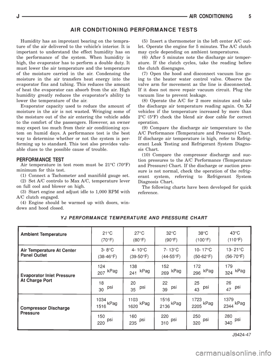
AIR CONDITIONING PERFORMANCE TESTS
Humidity has an improtant bearing on the tempra-
ture of the air delivered to the vehicle's interior. It is
important to understand the effect humidity has on
the performance of the system. When humidity is
high, the evaporator has to perform a double duty. It
must lower the air temperature and the temperature
of the moisture carried in the air. Condensing the
moisture in the air transfers heat energy into the
evaporator fins and tubing. This reduces the amount
of heat the evaporator can absorb from the air. High
humidity greatly reduces the evaporator 's ability to
lower the temperature of the air.
Evaporator capacity used to reduce the amount of
moisture in the air is not wasted. Wringing some of
the moisture out of the air entering the vehicle adds
to the comfort of the passengers. However, an owner
may expect too much from their air conditioning sys-
tem on humid days. A performance test is the best
way to determine whether or not the system is per-
forming up to standard. This test also provides valu-
able clues to the possible cause of trouble.
PERFORMANCE TEST
Air temperature in test room must be 21ÉC (70ÉF)
minimum for this test.
(1) Connect a Tachometer and manifold gauge set.
(2) Set A/C controls to Max A/C, temperature lever
on full cool and blower on high.
(3) Start engine and adjust idle to 1,000 RPM with
A/C clutch engaged.
(4) Engine should be warmed up with doors, win-
dows and hood closed.(5) Insert a thermometer in the left center A/C out-
let. Operate the engine for 5 minutes. The A/C clutch
may cycle depending on ambient temperatures.
(6) After 5 minutes note the discharge air temper-
ature. If the clutch cycles, take the reading before
the clutch disengages.
(7) Open the hood and disconnect vacuum line go-
ing to the heater water control valve. Observe the
valve arm for movement as the line is disconnected.
If it does not move repair vacuum circuit. Plug the
vacuum line to prevent leakage.
(8) Operate the A/C for 2 more minutes and take
the discharge air temperature reading again. On XJ
vehicles if the temperature increased by more than
2ÉC (5ÉF) check the blend air door cable for correct
operation.
(9) Compare the discharge air temperature to the
A/C Performance (Temperature and Pressure) Chart.
If discharge air temperature is high, refer to Refrig-
erant Leak Testing and Refrigerant System Diagno-
sis Chart.
(10) Compare the compressor discharge and suc-
tion pressures to the A/C Performance (Temperature
and Pressure) Chart. If the discharge or suction pres-
sure is not normal, check the operation of the refrig-
erant system, referring to Refrigerant System
Diagnosis Chart.
The following charts have been developed for quick
reference.
YJ PERFORMANCE TEMPERATURE AND PRESSURE CHART
JAIR CONDITIONING5
Page 1717 of 1784
REFRIGERANT LEAK TESTING, DISCHARGING, EVACUATING AND CHARGING
LEAK TESTING REFRIGERANT
WARNING: REVIEW WARNINGS AND CAUTIONS IN
GENERAL INFORMATION SECTION OF THIS
GROUP BEFORE LEAK TESTING.
If A/C system is not cooling properly, determine if
system is fully charged. Refer to Refrigerant System
Diagnosis Chart. If the system is empty evacuate the
A/C system and charge system with 0.283 kPa (0.6
lbs. or 10 oz.) R-134a refrigerant. Refer to Charging
Refrigerant System for instructions. To detect a leak
in the system, perform the following procedures.
(1) Position the vehicle in a wind free work area.
This will aid in detecting small leaks.
(2) Bring A/C system up to operating temperature
and pressure. This is done by allowing the engine to
run with the A/C on for 5 to 7 minutes.
(3) Open hood 5 minutes prior to leak test. This
will dissipate any accumulated refrigerant in the en-
gine compartment.
(4) With the engine not running, use an R-134a
Electronic Leak Detector and search for leaks. Move
probe slowly along the bottom side of lines and fit-
tings, because R-134a is heavier than air. Fittings,
lines, or components that appear to be oily usually
indicates a refrigerant leak.
(5) To inspect the evaporator core for leaks. Set the
blower at low speed and the selector in PANEL and
RECIRC mode check for leaks at CENTER panel ou-
lets.
DISCHARGING REFRIGERANT SYSTEM
WARNING: REVIEW WARNINGS AND CAUTIONS IN
GENERAL INFORMATION SECTION OF THIS
GROUP BEFORE DISCHARGING SYSTEM.
R-134a refrigrant is a hydrofluorocarbon (HFC)
that does not contain chlorine. R-134a refrigerant Re-
covery/Recycling Station that meets SAE standard
J2210 must be used to discharge the refrigerant sys-
tem. Refer to the operating instructions provided
with the equipment for proper operation.
EVACUATING REFRIGERANT SYSTEM
WARNING: REVIEW WARNINGS AND CAUTIONS IN
GENERAL INFORMATION SECTION OF THIS
GROUP BEFORE EVACUATING SYSTEM.If the A/C system has been open to the atmosphere,
it must be evacuated before the system can be
charged. Moisture and air mixed with refrigerant will
raise the compressor head pressure above acceptable
operating levels. This will reduce the performance of
the air conditioner and damage the compressor. Mois-
ture will boil at near room temperature when ex-
posed to vacuum. To evacuate the refrigerant system
use following procedure:
(1) Connect a suitable charging station and mani-
fold gauge set to the vehicle.
(2) Open the low and high side valves and start
vacuum pump. When suction gauge reads 88 kPag
(26 in. Hg) vacuum or greater, close all valves and
turn off vacuum pump. If system fails to reach spec-
ified vacuum, the system has a leak that must be
corrected. If system maintains the specified vacuum
for 30 minutes, start the vacuum pump. Then open
the suction and discharge valves and evacuate an ad-
ditional 10 minutes.
(3) Close all valves. Turn off and disconnect the
vacuum pump.
The system is now ready to be charged with refrig-
erant.
CHARGING REFRIGERANT SYSTEM
WARNING: REVIEW WARNINGS AND CAUTIONS IN
GENERAL INFORMATION SECTION OF THIS
GROUP BEFORE CHARGING SYSTEM.
After the system has been tested for leaks and
evacuated, a refrigerant charge can be injected into
the system. Refer to refrigerant capacities for proper
amount of refrigerant charge.
The most accurate method of charging is to com-
pletely evacuate the system. Then charge the system
using a Recovery/Recycling Station approved for
R-134a refrigerant. Refer to the operating instruc-
tions provided with the equipment for proper opera-
tion.
CAUTION: Do not over charge refrigerant system.
This will cause excessive compressor head pres-
sure and can cause noise and system failure.
REFRIGERANT CHARGE CAPACITY
The R-134a system charge capacity is 0.9 kPag (32
oz.) for XJ and YJ vehicles.
8 AIR CONDITIONINGJ
Page 1746 of 1784
ASSEMBLY REPLACEMENTÐYJ VEHICLES,
DRIVE AXLE; FRONT SUSPENSION AND
AXLE...............................2-21
ASSEMBLY REPLACEMENTÐYJ VEHICLES,
DRIVE AXLE; REAR SUSPENSION AND
AXLES..............................3-12
ASSEMBLY (SHORT BLOCK), SERVICE
ENGINE..............................9-4
ASSEMBLY TIPS, TRANSMISSION........21-146
ASSEMBLY, TRANSFER CASE......21-282,21-306
ASSEMBLYÐXJ VEHICLES, ENGINE....9-14,9-54
ASSEMBLYÐYJ VEHICLES, ENGINE....9-16,9-57
ASSEMBLY/INSTALLATION, PINION
GEAR; FRONT SUSPENSION AND AXLE....2-40
ASSEMBLY/INSTALLATION, PINION
GEAR; REAR SUSPENSION AND AXLES....3-22
ASSIST HANDLE, FULL-METAL DOOR.....23-175
ASSIST HANDLEÐXJ VEHICLES.........23-118
AUTO SHUT DOWN (ASD) RELAYÐPCM
OUTPUT............................14-24
AUTOMATIC BELT TENSIONERÐXJ
MODELS............................7-36
AUTOMATIC, PARK-LOCK CABLEÐ
CONSOLE SHIFT.....................19-45
AUTOMATIC SHUT DOWN (ASD) RELAY;
FUEL SYSTEM.......................14-54
AUTOMATIC SHUT DOWN (ASD) RELAY;
IGNITION SYSTEMS..........8D-1,8D-8,8D-20
AUTOMATIC SHUT DOWN (ASD) RELAY
TESTING...........................14-43
AUTOMATIC SHUT DOWN (ASD)
SENSEÐPCM INPUT..................14-19
AUTOMATIC TRANSMISSION..............0-23
AUTOMATIC TRANSMISSION, 30RH/
32RH..............................21-66
AUTOMATIC TRANSMISSION, AW-4.......21-156
AW-4 AUTOMATIC TRANSMISSION.......21-156
AW-4 BUSHING AND PISTON CLEARANCE . . 21-326
AW-4 CLUTCH AND BRAKE PACK
REQUIREMENTS....................21-328
AW-4 CLUTCH DISC AND PLATE
THICKNESS........................21-325
AW-4 GENERAL SPECIFICATIONS........21-324
AW-4 IN-VEHICLE SERVICE.............21-173
AW-4 OIL PUMP WEAR LIMITS..........21-325
AW-4 RETAINER AND PISTON
SPECIFICATIONS....................21-327
AW-4 TORQUE SPECIFICATIONS.........21-331
AW-4 TRANSMISSION DIAGNOSIS.......21-167
AW-4 TRANSMISSION OVERHAUL........21-192
AW-4 TRANSMISSION REMOVAL AND
INSTALLATION......................21-189
AW-4 VALVE AND SPRING
IDENTIFICATION....................21-330
AW-4 VALVE BODY CHECK BALL
DIMENSIONS.......................21-328
AX 15 MANUAL TRANSMISSION..........21-32
AX 15 MANUAL TRANSMISSION,
TORQUE SPECIFICATIONS.............21-320
AX 4/5 MANUAL TRANSMISSION..........21-1
AXLE (2WD), MODEL 30 AXLE AND TUBE . . . 2-20
AXLE 8 1/4 INCH, REAR.........3-29,3-44,3-50
AXLE ALIGNMENT, REAR..................3-8
AXLE AND TUBE AXLE (2WD), MODEL 30 . . . 2-20
AXLE ASSEMBLY REPLACEMENTÐXJ
VEHICLES, DRIVE; FRONT SUSPENSION
AND AXLE...........................2-21
AXLE ASSEMBLY REPLACEMENTÐ
XJ VEHICLES, DRIVE; REAR SUSPENSION
AND AXLES......................3-11,3-30
AXLE ASSEMBLY REPLACEMENTÐ
YJ VEHICLES, DRIVE; FRONT SUSPENSION
AND AXLE...........................2-21
AXLE ASSEMBLY REPLACEMENTÐ
YJ VEHICLES, DRIVE; REAR SUSPENSION
AND AXLES..........................3-12
AXLE BUSHING REPLACEMENT........2-11,2-32
AXLE, FRONT DRIVE.....................2-3
AXLE, MODEL 30 FRONT.............2-46,2-47
AXLE MODEL 35, REAR........3-11, 3-28, 3-50
AXLE NOISE/VIBRATION DIAGNOSIS;
FRONT SUSPENSION AND AXLE
..........2-16
AXLE NOISE/VIBRATION DIAGNOSIS;
REAR SUSPENSION AND AXLES
..........3-7
AXLE SHAFT
...........................3-14
AXLE SHAFTÐCARDAN U-JOINT
...........2-25AXLE SHAFT, HUB BEARING..............2-24
AXLE SHAFT OIL SEAL REPLACEMENT,
INNER..............................2-33
AXLE SHAFT SEAL AND BEARING..........3-15
AXLE SHAFT, SEAL AND BEARING
SERVICE............................3-31
AXLE SPECIFICATIONS; FRONT
SUSPENSION AND AXLE................2-46
AXLE SPECIFICATIONS; REAR
SUSPENSION AND AXLES...........3-28,3-44
AXLEÐYJ VEHICLES, VACUUM
DISCONNECT.........................2-26
AXLES................................3-1
AXLES, FRONT AND REAR................0-26
AXLE/SHIFT MOTOR DIAGNOSIS
DISCONNECT.....................2-28,2-27
BACKLASH AND CONTACT PATTERN
ANALYSIS; FRONT SUSPENSION AND AXLE . 2-44
BACKLASH AND CONTACT PATTERN
ANALYSIS; REAR SUSPENSION AND
AXLES..............................3-25
BACK-UP/REAR TURN SIGNAL/TAIL
LAMP BULB REPLACEMENT.............8L-9
BALANCE, TIRE AND WHEEL..............22-6
BALL DIMENSIONS, AW-4 VALVE BODY
CHECK............................21-328
BALL POWER STEERING GEAR,
RECIRCULATING.....................19-19
BALL STUD REPLACEMENT, LIFTGATE
SUPPORT ROD......................23-70
BALL STUDS, STEERING KNUCKLE.........2-30
BALL STUDS, STEERING LINKAGE.........0-30
BAND ADJUSTMENT, FRONT.............21-99
BAND ADJUSTMENT, REAR..............21-99
BAND ADJUSTMENTS, SPECIFICATIONS....21-66
BAND OVERHAUL, FRONT SERVO........21-136
BAND OVERHAUL, REAR SERVO.........21-136
BANKS, FUSE CHARTS AND RELAY........8W-8
BAR REPLACEMENT, SOUND..............8F-7
BAR, SPORT.........................23-171
BAR, STABILIZER...................2-10,2-14
BAR, TRACK; FRONT SUSPENSION AND
AXLE...........................2-10,2-13
BAR, TRACK; REAR SUSPENSION AND
AXLES...............................3-6
BARÐXJ VEHICLES, STABILIZER...........3-4
BASECOAT/CLEARCOAT................23-202
BASE/COLOR COAT...................23-201
BATTERY.............................0-18
BATTERY CHARGING....................8A-5
BATTERY CHARGING TIME TABLE..........8A-5
BATTERY CLASSIFICATIONS AND
RATINGS............................8A-8
BATTERY CLASSIFICATIONS AND
RATINGSÐLEFT HAND DRIVE..........8B-10
BATTERY CLASSIFICATIONS AND
RATINGSÐRIGHT HAND DRIVE.........8B-10
BATTERY DIAGNOSTICS CHART...........8A-7
BATTERY INDICATOR (BASE CLUSTER
ONLY), OPERATIONAL CHECK...........8A-14
BATTERY LOAD TEST....................8A-4
BATTERY MAINTENANCE.................8B-1
BATTERY OPEN CIRCUIT VOLTAGE.........8A-4
BATTERY OPEN CIRCUIT VOLTAGE TEST....8A-3
BATTERY REPLACEMENTÐLEFT HAND
DRIVE..............................8B-1
BATTERY REPLACEMENTÐRIGHT HAND
DRIVE..............................8B-2
BATTERY SERVICE PROCEDURES..........8B-1
BATTERY TEST PROCEDURES.............8A-2
BATTERY TESTING GENERAL
INFORMATION........................8A-3
BATTERY TORQUE SPECIFICATIONS.......8B-10
BATTERY TRAY..................23-13,23-140
BATTERY VOLTAGEÐPCM INPUT.........14-19
BATTERY/STARTING/CHARGING
SYSTEMS DIAGNOSTICS...............8A-1
BEAM ADJUSTMENT, FOG LAMP..........8L-12
BEAM ADJUSTMENT, HEADLAMP..........8L-3
BEARING AND AXLE SHAFT, HUB..........2-24
BEARING, AXLE SHAFT SEAL
..............3-15
BEARING FITTING CHART, CONNECTING
ROD
............................9-36,9-76
BEARING FITTING CHART, MAIN
.......9-43,9-83
BEARING LUBRICANTS, CHASSIS
COMPONENT AND WHEEL
..............0-30BEARING NOISE, GEAR AND; FRONT
SUSPENSION AND AXLE................2-16
BEARING NOISE, GEAR AND; REAR
SUSPENSION AND AXLES................3-7
BEARING REPLACEMENT, PILOT...........6-11
BEARING REPLACEMENT, PITMAN
SHAFT SEALS.......................19-32
BEARING REPLACEMENT, RELEASE.........6-11
BEARING SERVICE, AXLE SHAFT, SEAL......3-31
BEARINGS, CRANKSHAFT MAIN.......9-40,9-80
BEARINGS, FRONT WHEEL...............0-31
BELT, ACCESSORY DRIVE................0-20
BELT DIAGNOSIS.......................7-31
BELT DIAGNOSIS, SERPENTINE DRIVE......7-32
BELT INDICATOR, SEAT..................8E-4
BELT REMINDER LAMP, SEAT............8E-16
BELT SCHEMATICS......................7-34
BELT SERVICEÐEXCEPT RIGHT HAND
DRIVE..............................7-34
BELT SERVICEÐWITH RIGHT HAND
DRIVE..............................7-35
BELT TENSION........................8B-10
BELT TENSION, DRIVE...................7-38
BELT TENSIONÐEXCEPT RIGHT HAND
DRIVE (RHD).........................7-33
BELT TENSIONÐRIGHT HAND DRIVE (RHD) . . 7-34
BELT TENSION SPECIFICATIONS...........7-34
BELT TENSIONERÐXJ MODELS,
AUTOMATIC..........................7-36
BELT/BUCKLEÐXJ VEHICLES, FRONT
SHOULDER........................23-119
BELT/BUCKLEÐXJ VEHICLES,
REAR SHOULDER/LAP...............23-120
BELTS, ENGINE ACCESSORY DRIVE........7-31
BELTS, FRONT SHOULDER..............23-196
BELTS, REAR SHOULDER...............23-196
BENCH, GEAR ADJUSTMENTS............19-42
BEZEL, INSTRUMENT CLUSTER.....23-91,23-191
BEZEL REPLACEMENT, INDICATOR........8E-17
BLADE REPLACEMENT, FRONT WIPER......8K-8
BLEEDINGÐBRAKE FLUID AND LEVELÐ
BRAKELINES AND HOSES, BRAKE........5-13
BLEEDINGÐWITH ABS BRAKES, BRAKE.....5-14
BLEEDINGÐWITH STANDARD BRAKES,
BRAKE..............................5-13
BLOCK, CYLINDER..................9-45,9-85
BLOCK HEATER, ENGINE.................7-37
BLOCKSÐTWO-DOOR VEHICLES, FRONT
DOOR SPACER......................23-60
BLOWER CONTROLSÐXJ VEHICLES.......24-14
BLOWER MOTOR, A/C..................24-43
BLOWER MOTOR (HEATING).............24-40
BLOWER MOTOR RESISTORS
REPLACEMENT......................24-35
BLOWER MOTOR/AIR DOOR MOTOR
SWITCH REPLACEMENT...............24-39
BLOWER MOTOR/FAN REPLACEMENT......24-26
BODY...............................13-18
BODY ASSEMBLY AND ADJUSTMENT,
VALVE ............................21-144
BODY CHECK BALL DIMENSIONS, AW-4
VALVE ............................21-328
BODY CODE LETTERS, JEEP...............5-2
BODY COLORS, EXTERIOR..............23-204
BODY COMPONENTS....................0-34
BODY COMPONENTS, CHASSIS............0-30
BODY COMPONENTSÐREFINISHING......23-200
BODY COMPONENTSÐYJ VEHICLES......23-132
BODY DISASSEMBLY AND INSPECTION,
VALVE
............................21-138
BODY EXTENSION PANELS AND
FASCIASÐYJ RENEGADE VEHICLES
.....23-147
BODY INSTALLATION, TRANSMISSION
VALVE
............................21-177
BODY INSTALLATION, VALVE
............21-101
BODY LUBRICANT SPECIFICATIONS
........0-35
BODY OVERHAUL, TRANSMISSION
VALVE
............................21-240
BODY REMOVAL, TRANSMISSION
VALVE
............................21-176
BODY REMOVAL, VALVE
...............21-100
BODY SERVICE INFORMATION, GENERAL
....23-1
BODY SERVICE, VALVE
................21-100
BODY SIDE MOULDING/CLADDING
........23-19
BODY SIDE STEP MOULDING
...........23-145
2 INDEXJ
Description Group-Page Description Group-Page Description Group-Page
Page 1747 of 1784
BODY SOLENOIDS, TRANSMISSION
VALVE ............................21-175
BODY STRIPES/DECALS...........23-25,23-153
BODY, THROTTLE.................14-29,14-59
BODY UNDERCOAT....................23-203
BOOSTER CHECK VALVE TEST, POWER......5-11
BOOSTER INSTALLATION, POWER
BRAKE..........................5-23,5-51
BOOSTER OPERATION, POWER BRAKE......5-22
BOOSTER, POWER BRAKE............5-22,5-40
BOOSTER REMOVAL, POWER BRAKE . . . 5-22,5-51
BOOSTER TEST, MASTER CYLINDER/
POWER.............................5-11
BOOSTER VACUUM TEST, POWER..........5-12
BORES, HONING CYLINDER................9-2
BOX, GLOVE.........................23-194
BRACKET, FUEL FILTER.................23-86
BRACKET, FUEL FILTER SHIELD...........13-17
BRACKET, I/P TWEETER SPEAKER/
COURTESY LAMP SUPPORT............23-95
BRACKET, MUFFLER/TAILPIPE HANGER.....13-16
BRACKET, REARVIEW MIRROR
RETAINING........................23-183
BRACKET REPLACEMENT, INTERIOR
REARVIEW MIRROR SUPPORT..........23-75
BRACKETS, CATALYTIC CONVERTER/
MUFFLER/TAILPIPE SUPPORT...........23-85
BRACKETSÐXJ VEHICLES, SPARE TIRE/
WHEEL HOLDDOWN AND FLOOR.......23-128
BRAKE ADJUSTMENT, DRUM..............5-35
BRAKE ADJUSTMENT PARKING............5-63
BRAKE BLEEDINGÐBRAKE FLUID AND
LEVELÐBRAKELINES AND HOSES........5-13
BRAKE BLEEDINGÐWITH ABS BRAKES.....5-14
BRAKE BLEEDINGÐWITH STANDARD
BRAKES.............................5-13
BRAKE BOOSTER INSTALLATION,
POWER.........................5-23,5-51
BRAKE BOOSTER OPERATION, POWER......5-22
BRAKE BOOSTER, POWER............5-22,5-40
BRAKE BOOSTER REMOVAL, POWER . . . 5-22,5-51
BRAKE CABLE TENSIONER REPLACEMENT
(XJ), PARKING........................5-61
BRAKE CHECK, PRELIMINARY..............5-7
BRAKE COMPONENTS, WHEEL.............5-1
BRAKE DIAGNOSIS, ABS..................5-3
BRAKE DIAGNOSIS, SERVICE..............5-7
BRAKE DRUM REFINISHING..............5-37
BRAKE FLUID CONTAMINATION............5-13
BRAKE FLUID, IMPORTANCE OF CLEAN.....5-48
BRAKE FLUID LEVEL....................5-13
BRAKE FLUID, RECOMMENDED........5-13,5-48
BRAKE FLUID TUBE RETAINER CLIP,
FUEL AND; BODY COMPONENTSÐXJ
VEHICLES..........................23-86
BRAKE FLUID TUBE RETAINER CLIP,
FUEL AND; FRAME AND BUMPERS......13-16
BRAKE FLUID/LUBRICANTS/CLEANING
SOLVENTS............................5-1
BRAKE FRONT CABLE REPLACEMENT
(YJ), PARKING........................5-62
BRAKE INDICATOR INOPERATIVE..........8E-4
BRAKE INDICATOR LAMP; INSTRUMENT
PANEL AND GAUGESÐXJ...............8E-2
BRAKE INDICATOR LAMP; INSTRUMENT
PANEL AND GAUGESÐYJ
..............8E-16
BRAKE LEVER INSTALLATION (XJ WITH
FULLCONSOLE), PARKING
..............5-60
BRAKE LEVER INSTALLATION (XJ WITH
MINICONSOLE), PARKING
...............5-58
BRAKE LEVER INSTALLATION (XJ
WITHOUT CONSOLE), PARKING
..........5-60
BRAKE LEVER REMOVAL (XJ WITH FULL
CONSOLE), PARKING
..................5-59
BRAKE LEVER REMOVAL (XJ WITH MINI
CONSOLE), PARKING
..................5-58
BRAKE LEVER REMOVAL (XJ WITHOUT
CONSOLE), PARKING
..................5-60
BRAKE OPERATION, PARKING
.............5-56
BRAKE OVERHAUL, SECOND
............21-232
BRAKE PACK REQUIREMENTS, AW-4
CLUTCH
...........................21-328
BRAKE PEDAL AND BRAKELIGHT
SWITCH
.............................5-65
BRAKE PEDAL INSTALLATION
.............5-66BRAKE PEDAL INSTALLATION (YJ),
PARKING............................5-61
BRAKE PEDAL REMOVAL.................5-65
BRAKE PEDAL REMOVAL (YJ), PARKING....5-61
BRAKE PEDAL SERVICE..................5-65
BRAKE PISTON AND TRANSMISSION
CASE OVERHAUL, FIRST-REVERSE......21-237
BRAKE PROBLEMS, DIAGNOSING
PARKING............................5-10
BRAKE PROBLEMS, DIAGNOSING
SERVICE.............................5-8
BRAKE REAR CABLE REPLACEMENT
(XJ), PARKING........................5-62
BRAKE REAR CABLE REPLACEMENT (YJ),
PARKING............................5-63
BRAKE ROTOR REFINISHING, DISC.........5-32
BRAKE ROTOR RUNOUT, DISC............5-31
BRAKE ROTOR THICKNESS, DISC..........5-31
BRAKE ROTOR THICKNESS VARIATION,
DISC...............................5-31
BRAKE SAFETY PRECAUTIONS.............5-2
BRAKE SERVO, SECOND COAST.........21-181
BRAKE SWITCH.......................14-54
BRAKE SWITCHÐPCM INPUT............14-20
BRAKE SYSTEM (ABS), ANTILOCK..........5-1
BRAKE SYSTEM (ABS) INDICATOR
LAMP, ANTI-LOCK.....................8E-2
BRAKE SYSTEM OPERATION, ANTILOCK.....5-43
BRAKE SYSTEM, POWER.................0-32
BRAKE TORQUE SPECIFICATIONS..........5-67
BRAKE WARNING LIGHT DISPLAY...........5-4
BRAKE WARNING LIGHTS.................5-1
BRAKELIGHT SWITCH ADJUSTMENT........5-66
BRAKELIGHT SWITCH, BRAKE PEDAL.......5-65
BRAKELIGHT SWITCH INSTALLATION.......5-66
BRAKELIGHT SWITCH REMOVAL...........5-66
BRAKELINE CHARTS....................5-15
BRAKELINES AND HOSES................5-15
BRAKELINING MATERIAL..................5-1
BRAKES, BRAKE BLEEDINGÐWITH ABS.....5-14
BRAKES, BRAKE BLEEDINGÐWITH
STANDARD..........................5-13
BRAKES, DISC.........................5-24
BRAKES, DRUM........................5-34
BRAKES, PARKING......................5-56
BRAKES, POWER........................5-1
BRAKESHOE INSTALLATION, DISC..........5-26
BRAKESHOE INSTALLATION, DRUM........5-34
BRAKESHOE REMOVAL, DISC.............5-25
BRAKESHOE REMOVAL, DRUM............5-34
BRAKING MODE, ABS OPERATION IN
ANTILOCK...........................5-43
BRAKING MODE, ABS OPERATION
IN NORMAL..........................5-43
BREAK-IN, ENGINE......................0-13
BRUSH GUARD........................23-3
BUCKET SEAT COMPONENTS, POWER....23-106
BUCKET SEAT CUSHION AND COVER......23-98
BUCKET SEAT PLATFORM AND TRACKS . . . 23-105
BUCKET SEATBACK COVER AND FRAME . . . 23-100
BUCKET SEATBACK RECONDITIONING.....23-102
BUCKET SEATS, FRONT.................23-97
BUFFING AND POLISHING..............23-203
BULB REPLACEMENT, BACK-UP/REAR
TURN SIGNAL/TAIL LAMP...............8L-9
BULB REPLACEMENT, FRONT PARK/
TURN SIGNAL LAMP
...................8L-8
BULB REPLACEMENT, HEADLAMP
..........8L-3
BULB REPLACEMENT, INSTRUMENT
CLUSTER
...........................8E-19
BULB REPLACEMENT, SIDE MARKER
LAMP
...............................8L-7
BULB REPLACEMENT, UNDERHOOD
LAMP
..............................8L-18
BULB REPLACEMENTÐYJ VEHICLES,
HARDTOP DOME/CARGO LAMP
.........8L-20
BULB/ELEMENT REPLACEMENT, FOG
LAMP
..............................8L-13
BUMPER, FRONT
..................13-3,13-14
BUMPER, LIFTGATE LICENSE PLATE
SCREW ANCHOR
.....................23-72
BUMPER, REAR
...................13-6,13-18
BUMPER, REAR JOUNCE
................13-18
BUMPERÐXJ VEHICLES, REAR
SEATBACK LATCH STRIKER
...........23-111BUMPERS AND FRAME ATTACHED
COMPONENTS, YJ....................13-14
BUMPERS, FUEL FILLER DOOR...........23-31
BUMPERS, XJ.........................13-3
BUSHING AND PISTON CLEARANCE, AW-
4 ................................21-326
BUSHING REPLACEMENT, AXLE.......2-11,2-32
BUSHING REPLACEMENT, LEAF SPRING
EYE; FRONT SUSPENSION AND AXLE.....2-15
BUSHING REPLACEMENT, LEAF SPRING
EYE; REAR SUSPENSION AND AXLES . . . 3-4,3-6
BUZZER SYSTEM, CHIME/WARNING........8A-1
CABLE, ACCELERATOR PEDAL AND
THROTTLE.....................14-16,14-54
CABLE ADJUSTMENT, PARK INTERLOCK . . . 21-186
CABLE ADJUSTMENT, SHIFT............21-186
CABLE ADJUSTMENT, TRANSMISSION
THROTTLE....................21-98,21-185
CABLE ADJUSTMENT, TRANSMISSION
THROTTLE VALVE....................21-70
CABLE ADJUSTMENT (XJ), PARK
INTERLOCK.........................21-97
CABLE ADJUSTMENT (XJ), SHIFT.........21-97
CABLE REPLACEMENT, HEATER
CONTROL..........................24-30
CABLE REPLACEMENT, LATCH
RELEASE...........................23-10
CABLE REPLACEMENT, SERVO............8H-9
CABLE REPLACEMENT, TRANSMISSION
THROTTLE.........................21-184
CABLE REPLACEMENT (XJ),
PARKING BRAKE REAR.................5-62
CABLE REPLACEMENT (YJ), PARKING
BRAKE FRONT........................5-62
CABLE REPLACEMENT (YJ), PARKING
BRAKE REAR.........................5-63
CABLE RESISTANCE, SPARK PLUG........8D-18
CABLE TENSIONER REPLACEMENT (XJ),
PARKING BRAKE......................5-61
CABLE, THROTTLE.....................14-16
CABLEÐCONSOLE SHIFT AUTOMATIC,
PARK-LOCK.........................19-45
CABLES, DISTRIBUTOR CAP AND ROTOR,
IGNITION............................0-18
CABLES, SPARK PLUG SECONDARY . . 8D-17,8D-29
CABLES, VENT DOOR CONTROL..........24-39
CALIBRATION VALUES, GAUGE...........8E-22
CALIPER ASSEMBLY....................5-29
CALIPER CLEANING AND INSPECTION......5-28
CALIPER DISASSEMBLY..................5-27
CALIPER INSTALLATION..................5-30
CALIPER OPERATION AND WEAR
COMPENSATION......................5-24
CALIPER REMOVAL.....................5-27
CAMSHAFT........................9-29,9-69
CAMSHAFT PIN REPLACEMENT........9-31,9-71
CAMSHAFT POSITION SENSOR; FUEL
SYSTEM............................14-54
CAMSHAFT POSITION SENSOR;
IGNITION SYSTEMS..............8D-1,8D-20
CAMSHAFT POSITION SENSORÐPCM
INPUT.............................14-20
CAMSHAFT POSITION SENSOR TEST;
FUEL SYSTEM.......................14-43
CAMSHAFT POSITION SENSOR TEST;
IGNITION SYSTEMS...................8D-8
CANADA ONLY, DAYTIME RUNNING
LIGHTS............................8L-16
CANISTER, EVAP...................25-4,25-9
CAP AND ROTOR, IGNITION CABLES,
DISTRIBUTOR........................0-18
CAP, DISTRIBUTOR.....................8D-9
CAP, FUEL TANK FILLER TUBE; EMISSION
CONTROL SYSTEMS...............25-4,25-9
CAP, FUEL TANK FILLER TUBE; FUEL
SYSTEM............................14-12
CAP, RADIATOR PRESSURE...............7-20
CAPACITIES, COOLING SYSTEM...........7-38
CAPACITIES, FLUID......................0-4
CAPACITIES, FUEL TANK...........14-12,14-62
CAPACITY TEST, FUEL PUMP..............14-7
CAR REPLACEMENT, PITMAN SHAFT
SEALSÐIN
.........................19-21
CARDAN (CV), DOUBLE
.................16-10
CARDAN, SINGLE
.......................16-9
CARDAN U-JOINT, AXLE SHAFT
............2-25
JINDEX3
Description Group-Page Description Group-Page Description Group-Page