1994 JEEP CHEROKEE open gas tank
[x] Cancel search: open gas tankPage 973 of 1784
FUEL TANKS
INDEX
page page
Fuel Gauge Sending Unit.................. 15
Fuel Tank.............................. 12
Fuel Tank Filler Tube Cap................. 12
Fuel Tank Pressure Relief/Rollover Valve...... 15General Information....................... 12
Heat Shields............................ 12
No-Lead Fuel Tank Filler Tube.............. 12
GENERAL INFORMATION
All vehicles pass a full 360 degree rollover test
without fuel leakage. To accomplish this, fuel and
vapor flow controls are required for all fuel tank con-
nections.
All models are equipped with a pressure relief/roll-
over valve mounted in the top of the fuel pump mod-
ule. The return line from the fuel pump to the fuel
tank contains a one-way check valve.
An evaporative control system prevents raw fuel
vapor from escaping into the atmosphere. Fuel va-
pors from the fuel tank are collected in the EVAP
canister. When the engine is operating, the vapors
are drawn into the intake manifold to be used in
combustion. Refer to Group 25, Emission Control
System for more information.
Inspect all hose/tube connections for completeness.
Be sure that leaks are not present. Replace any hose
that is cracked, scuffed, swelled, has rubbed against
other vehicle components or shows any other sign of
wear that could lead to failure. If it is necessary to
replace a hose, only hose marked EFM/EFI may be
used.
When installing hoses, be sure that they are routed
away from contact with other vehicle components.
The hose clamps used on fuel injected vehicles are
of a special rolled edge construction to prevent the
edge of the clamp from cutting into the hose. Only
these rolled edge type clamps may be used on this
system. Other types of clamps may cut into the hoses
and cause high pressure fuel leaks.
NO-LEAD FUEL TANK FILLER TUBE
All vehicles are designed to operate using Un-
leaded fuels. The diameter of the opening in the fuel
tank filler neck is sized to only accept unleaded fuel
nozzles. Gasoline station pumps for unleaded and
leaded fuels have different size nozzles. Leaded fuel
nozzles are larger in diameter than unleaded nozzles.
The fuel tank filler neck opening is also equipped
with a deflector, which the smaller unleaded nozzle
pushes back upon entering the filler neck. The de-
flector will prevent the larger diameter leaded fuel
nozzles from entering the filler neck and will deflect
fuel away from the filler neck. This happens if filling
of the tank with leaded fuel is attempted.
A label is attached to the instrument panel under
the fuel gauge that reads UNLEADED FUEL ONLY
as a reminder to the driver. A similar label is located
near the fuel tank filler.
FUEL TANK FILLER TUBE CAP
The loss of any fuel or vapor out of the filler neck
is prevented by the use of a safety filler cap. This
will release only under pressure of 10.9 to 13.45 kPa
(1.58 to 1.95 psi). The vacuum release is between .97
and 2.0 kPa (.14 and .29 psi). This cap must be re-
placed by a similar unit if replacement is necessary.
CAUTION: Remove the fuel tank filler tube cap prior
to removing or repairing fuel lines to relieve fuel
tank pressure.
HEAT SHIELDS
The sheet metal heat shields may have to be re-
moved when servicing the fuel tank, fuel lines or va-
por vent line. The heat shields must be installed to
protect the lines and tank from the heat of the ex-
haust system. Refer to Group 11, Exhaust System
and Intake Manifold for proper installation.
FUEL TANK
WARNING: THE FUEL SYSTEM IS UNDER CON-
STANT FUEL PRESSURE (EVEN WITH THE ENGINE
OFF) OF APPROXIMATELY 131-269 KPA (19-39
PSI). THIS PRESSURE MUST BE RELEASED BE-
FORE SERVICING FUEL TANK.
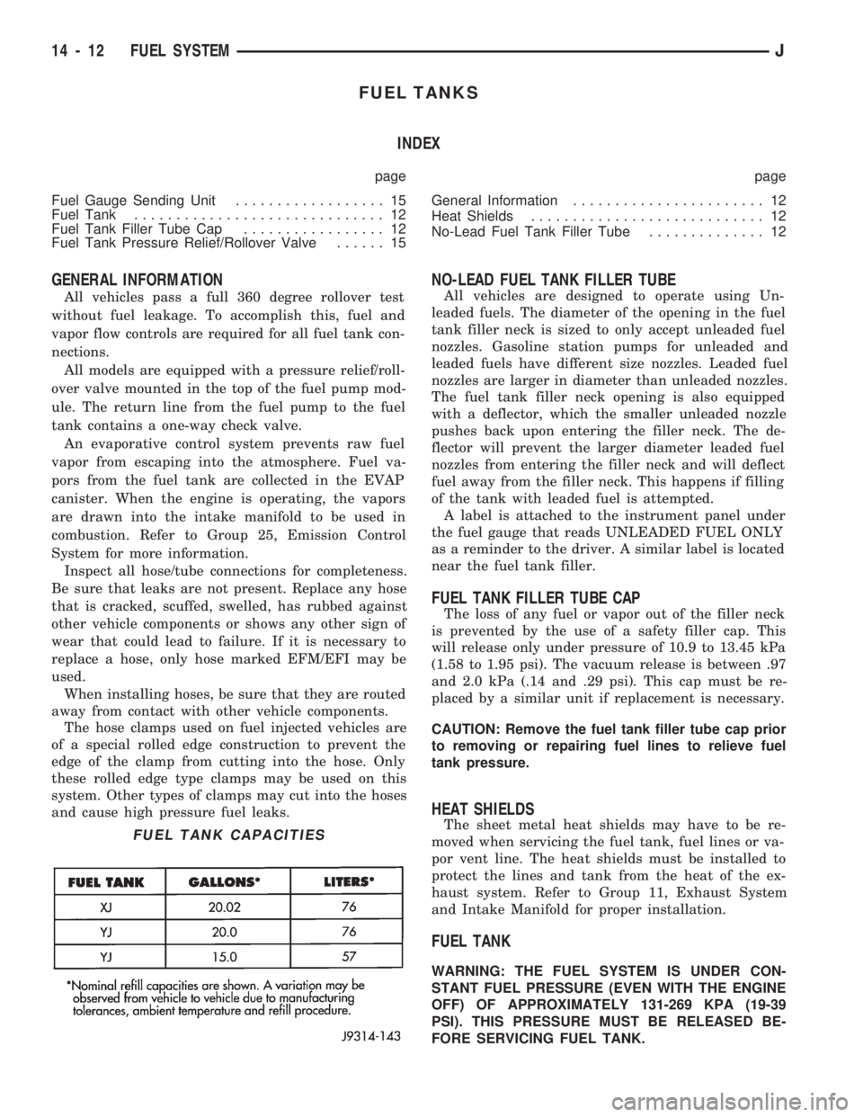
FUEL TANK CAPACITIES
14 - 12 FUEL SYSTEMJ
Page 975 of 1784
REMOVALÐYJ MODELS
WARNING: EXTINGUISH ALL TOBACCO SMOKING
PRODUCTS BEFORE SERVICING THE FUEL SYS-
TEM. KEEP OPEN FLAME AWAY FROM FUEL SYS-
TEM COMPONENTS.
(1) Disconnect negative battery cable.
(2) Remove the fuel filler cap. Using an approved por-
table gasoline siphon/storage tank, drain fuel tank.
(3) Raise and support vehicle.
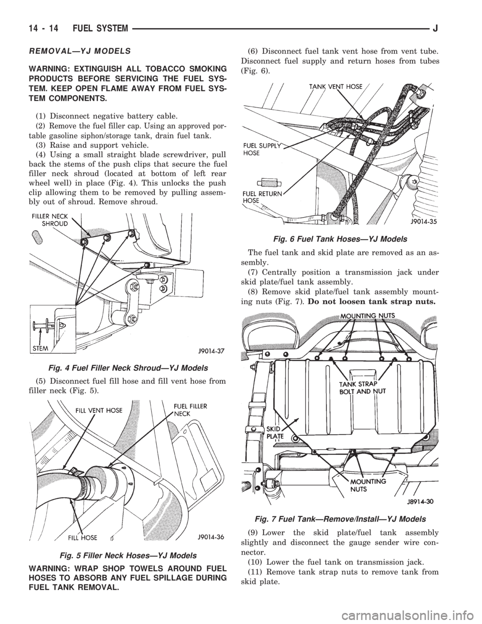
(4) Using a small straight blade screwdriver, pull
back the stems of the push clips that secure the fuel
filler neck shroud (located at bottom of left rear
wheel well) in place (Fig. 4). This unlocks the push
clip allowing them to be removed by pulling assem-
bly out of shroud. Remove shroud.
(5) Disconnect fuel fill hose and fill vent hose from
filler neck (Fig. 5).
WARNING: WRAP SHOP TOWELS AROUND FUEL
HOSES TO ABSORB ANY FUEL SPILLAGE DURING
FUEL TANK REMOVAL.(6) Disconnect fuel tank vent hose from vent tube.
Disconnect fuel supply and return hoses from tubes
(Fig. 6).
The fuel tank and skid plate are removed as an as-
sembly.
(7) Centrally position a transmission jack under
skid plate/fuel tank assembly.
(8) Remove skid plate/fuel tank assembly mount-
ing nuts (Fig. 7).Do not loosen tank strap nuts.
(9) Lower the skid plate/fuel tank assembly
slightly and disconnect the gauge sender wire con-
nector.
(10) Lower the fuel tank on transmission jack.
(11) Remove tank strap nuts to remove tank from
skid plate.
Fig. 4 Fuel Filler Neck ShroudÐYJ Models
Fig. 5 Filler Neck HosesÐYJ Models
Fig. 6 Fuel Tank HosesÐYJ Models
Fig. 7 Fuel TankÐRemove/InstallÐYJ Models
14 - 14 FUEL SYSTEMJ
Page 1665 of 1784
WARNING: LARGE AMOUNTS OF REFRIGERANT
RELEASED IN A CLOSED WORK AREA WILL DIS-
PLACE THE OXYGEN AND CAUSE SUFFOCATION.
ALWAYS MAINTAIN GOOD VENTILATION SUR-
ROUNDING THE WORK AREA.
R-12 gas, under normal conditions, is non-poison-
ous.
WARNING: THE DISCHARGE OF R-12 GAS NEAR
AN OPEN FLAME CAN PRODUCE A VERY POISON-
OUS GAS CALLED PHOSGENE. PHOSGENE IS
GENERATED WHEN A FLAME-TYPE LEAK DETEC-
TOR IS USED.
CAUTION: When charging an A/C system always
keep the tank in an upright position. If the tank is
on its side or upside down, liquid refrigerant will
enter the system and may damage the compressor.
In most instances when charging or adding refrig-
erant, moderate heat is required to bring the pres-
sure of the refrigerant above the pressure of the
system. A bucket or large pan of hot water, not over
52ÉC (125ÉF), is all the heat required for this pur-
pose. DO NOT heat the refrigerant container with a
blow torch or any other means that would raise the
temperature and pressure above this temperature.
CAUTION: DO NOT allow liquid refrigerant to touch
bright metal. Refrigerant will tarnish bright metal
and chrome surfaces. Refrigerant in combination
with moisture is very corrosive and can cause ex-
tensive damage to all metal surfaces.
Avoid splashing the refrigerant on any surface.
RECYCLING
(R-12) refrigerant is a chloroflorocarbon (CFC) that
can contribute to the depletion of the ozone layer in
the upper atmosphere. Ozone filters out harmful ra-
diation from the sun. To assist in protecting the
ozone layer, Chrysler Corporation requires that an
(R-12) refrigerant recovery device that meets SAE
standard J1991 be used. Contact an automotive ser-
vice equipment supplier for refrigerant recycling
equipment that is available in your area. Refer to
the operating instructions provided with the recy-
cling equipment for proper operation.
SERVICE PRECAUTIONS
Never open or loosen a connection before discharg-
ing the system refrigerant.
A system which has been opened to replace a com-
ponent or one which has discharged through leakage
must be evacuated before charging.
Immediately after disconnecting a component from
the system, seal the open fittings with a cap or plug.Before disconnecting a component from the system,
clean the outside of the fittings thoroughly.
DO NOT remove the sealing caps from a replace-
ment component until ready to install.
Refrigerant oil will absorb moisture from the atmo-
sphere if left uncapped. DO NOT open an oil con-
tainer until ready to use and install the cap
immediately after using. Store the oil only in a clean
moisture-free container.
Before connecting an open fitting always install a
new seal ring. Coat the fitting and seal with clean
refrigerant oil before connecting.
When installing a refrigerant line avoid sharp
bends. Position the line away from the exhaust or
any sharp edges which may chafe the line.
Tighten fittings only to the specified torque. The
copper and aluminum fittings used in the A/C system
will not tolerate over tightening.
When disconnecting a fitting use a wrench on both
halves of the fitting to prevent twisting of the refrig-
erant lines or tubes.
DO NOT open a refrigerant system or uncap a re-
placement component unless it is as close as possible
to room temperature. This will prevent condensation
from forming inside of a component which is cooler
than the surrounding air.
Keep service tools and the work area clean. Con-
tamination of A/C system through careless work hab-
its must be avoided.
PRESSURE GAUGE AND MANIFOLD ASSEMBLY
Pressure Gauge and Manifold Assembly Tool
C-3740-B (Fig. 1) is the most important tool used to
service the air conditioning system. The gauge as-
sembly is used to determine:
²System high side gauge pressures
²System low side gauge pressures
²The correct refrigerant charge
²System diagnosis
It is designed to provide simultaneous high and low
side pressure indications, because these pressures
must be compared to determine the correct system
operation.
LOW SIDE GAUGE
The low side gauge is a compound gauge, which
means that it will register both pressure and vacuum
(Fig. 1). The compound gauge is calibrated 0-1034
kPa (0-150 psi) pressure and 0-760 mm (0-30 in.) of
mercury vacuum. It is connected to the suction ser-
vice valve to check the low side pressure or vacuum.
HIGH SIDE GAUGE
The high side gauge is used to check the pressure
in the discharge side of the air conditioning system
(Fig. 1).
24 - 2 HEATING AND AIR CONDITIONINGJ
Page 1722 of 1784
EVAPORATIVE EMISSION CONTROLS
INDEX
page page
Crankcase Ventilation System................ 5
EVAP (Evaporation) Control System........... 4
EVAP Canister........................... 4Fuel Tank Filler Tube Cap.................. 4
Pressure Relief/Rollover Valve................ 5
EVAP (EVAPORATION) CONTROL SYSTEM
GENERAL INFORMATION
The function of the EVAP control system is to pre-
vent the emissions of gasoline vapors from the fuel
tank into the atmosphere. When fuel evaporates in
the fuel tank, the vapors pass through vent hoses or
tubes to a carbon filled EVAP canister. They are
temporarily held in the canister until they can be
drawn into the intake manifold when the engine is
running.
The EVAP canister is a feature on all models for
the storage of fuel vapors from the fuel tank.
The hoses used in this system are specially
manufactured. If replacement becomes neces-
sary, it is important to use only fuel resistant
hose.
EVAP CANISTER
A sealed, maintenance free, EVAP canister is used
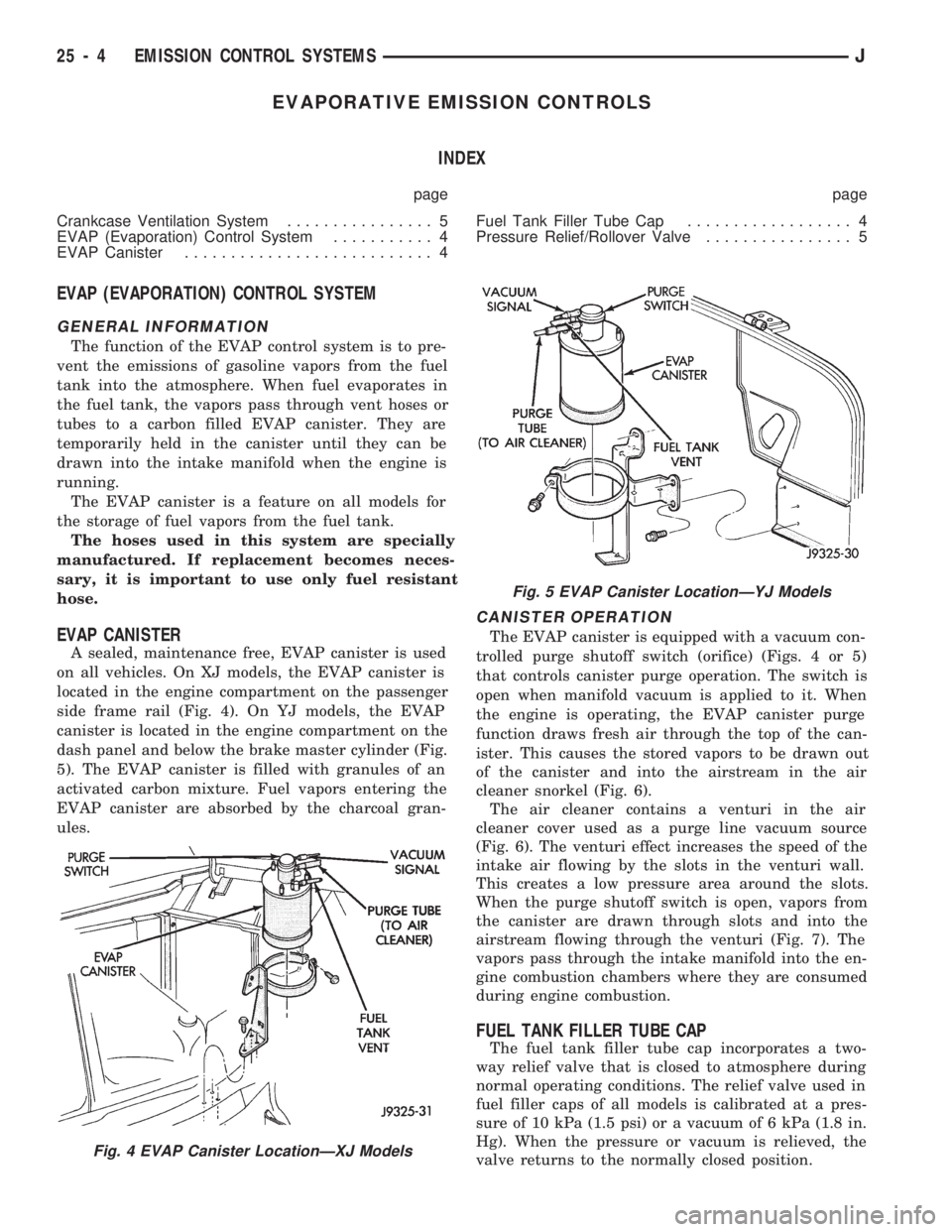
on all vehicles. On XJ models, the EVAP canister is
located in the engine compartment on the passenger
side frame rail (Fig. 4). On YJ models, the EVAP
canister is located in the engine compartment on the
dash panel and below the brake master cylinder (Fig.
5). The EVAP canister is filled with granules of an
activated carbon mixture. Fuel vapors entering the
EVAP canister are absorbed by the charcoal gran-
ules.
CANISTER OPERATION
The EVAP canister is equipped with a vacuum con-
trolled purge shutoff switch (orifice) (Figs. 4 or 5)
that controls canister purge operation. The switch is
open when manifold vacuum is applied to it. When
the engine is operating, the EVAP canister purge
function draws fresh air through the top of the can-
ister. This causes the stored vapors to be drawn out
of the canister and into the airstream in the air
cleaner snorkel (Fig. 6).
The air cleaner contains a venturi in the air
cleaner cover used as a purge line vacuum source
(Fig. 6). The venturi effect increases the speed of the
intake air flowing by the slots in the venturi wall.
This creates a low pressure area around the slots.
When the purge shutoff switch is open, vapors from
the canister are drawn through slots and into the
airstream flowing through the venturi (Fig. 7). The
vapors pass through the intake manifold into the en-
gine combustion chambers where they are consumed
during engine combustion.
FUEL TANK FILLER TUBE CAP
The fuel tank filler tube cap incorporates a two-
way relief valve that is closed to atmosphere during
normal operating conditions. The relief valve used in
fuel filler caps of all models is calibrated at a pres-
sure of 10 kPa (1.5 psi) or a vacuum of 6 kPa (1.8 in.
Hg). When the pressure or vacuum is relieved, the
valve returns to the normally closed position.
Fig. 4 EVAP Canister LocationÐXJ Models
Fig. 5 EVAP Canister LocationÐYJ Models
25 - 4 EMISSION CONTROL SYSTEMSJ