1994 JAGUAR XJ6 sensor
[x] Cancel search: sensorPage 481 of 521

84
- Security System - RESTRICTED /SSU€
A5.2.7 Inclination sensor
Located adjacent to the SLCM underthe luggage compartment LH side linerto give indication of unauthorized jacking / lifting of the vehicle.
A5.2.8 Intrusion sensors
Located above each front door to give indication of unauthorized entry into the vehicle passenger compartment.
A5.2.9 Reader exciter coil
Forms an integral part of the ignition switch to prove correct key insertion by communicating key transponder signal
to control module.
A5.2.10 Reader exciter module
Located on the steering column to receive signals from the reader/ exciter coil and disarm the engine immobilization
system on correct demand.
A5.2.11 Security active indicator
An LED built into the central locking switch to indicate when security system is armed.
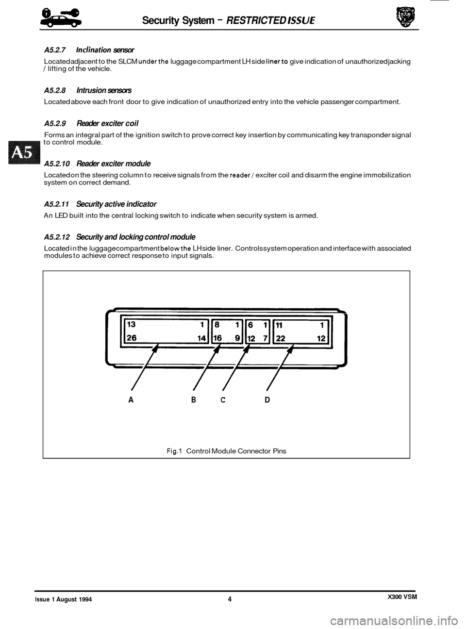
A5.2.12 Security and locking control module
Located in the luggage compartment belowthe LH side liner. Controls system operation and interface with associated
modules to achieve correct response to input signals.
L
Fig.1 Control Module Connector Pins
/ // /
A B C D
X300 VSM Issue 1 August 1994 4
Page 482 of 521

Security System
Pin No. Signal Description
01 0 / P Deadlock (front right / rear left)
02
0 / P Unlock driver's door
03
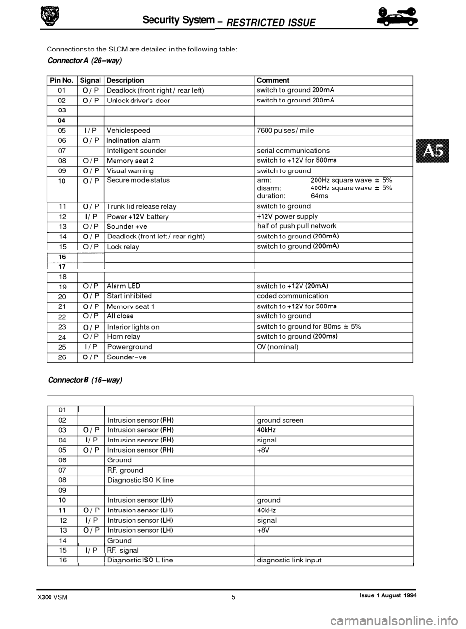
Connections to the SLCM are detailed in the following table:
9 Connector A (26-way)
Comment
switch to ground 200mA
switch to ground 200mA
05 I/P
06
0 / P
07
08 O/P
09
0 / P
10 0 / P Vehiclespeed
7600 pulses
/ mile
Inclination alarm
Intelligent sounder serial communications
Memoryseat2
Visual warning switch to ground
Secure mode status arm:
200Hz square wave f 5%
400Hz square wave f 5%
switch
to
+12V for 500ms
disarm:
duration: 64ms
0
117- I I
11 0 / P Trunk lid release relay 1 switch to ground
12
I / P Power +12V battery 1 + 12V power supply
13 O/P
Sounder+ve half of push pull network
14
0 / P Deadlock
(front left / rear right) switch to ground (200mA)
15 O/P Lock relay switch
to ground (200mA)
18
19
20 21 O/P
AlarmLED switch
to +12V (20mA)
0 / P Start inhibited coded communication
0 / P Memorv seat 1 switch
to +12V for 500ms
Connector 8 (16-way)
22
23
24
25
26 O/P
Allclose switch
to ground
0 / P
O/P Horn relay switch to ground
(200ms)
I/P Powerground OV (nominal)
OJP Sounder-ve
Interior lights
on switch
to ground for 80ms
f 5%
01
I
02
03 04
05
06
07
08
09
I I I I 15 I I / P I R.F. sianal
Intrusion
sensor
(RH) ground screen
0 / P Intrusion sensor (RH) 40kHz
I / P Intrusion sensor (RH) signal
0 / P Intrusion sensor (RH) +8V
Ground
R.F. ground
Diagnostic
IS0 K line
I. I - I 16 I I Diaanostic IS0 L line 1 diagnostic link input
10
11
12
13
14
.I
I I" 1- I
Intrusion sensor (LH) ground
0 / P Intrusion sensor (LH) 40kHz
I / P Intrusion sensor (LH) signal
0 / P Intrusion sensor (LH) +8V
Ground
Issue 1 August 1994 X300 VSM 5
84
- RESTRICTED ISSUE -
Page 485 of 521

Security System - RESTRICTED ISSUE 8-8
-
A5.3.2 Security system
Base system
Provides standard vehicle arming, ie door ajar, actuator lockstatus, trunk lid or hood ajar and passenger door unlock- ing, does not include inclination or
Intrusion sensing
Detection of intrusion into the passenger compartment by removal or breakage of any glazed area, entry via any pro- tected enclosure and unauthorized door opening detection.
Inclination (tilt) sensing
Detection of unauthorized jacking /towing.
Passive arming
Arming of the security system, excluding intrusion sensors, without audible confirmation.
Audible tones
Audible indication of driver error when attempting to arm the system, or on initiation of deadlocking.
Engine immobilization
Automatic immobilization of the engine crank facility whenever the ignition key is turned to position 0.
A5.3.3 Convenience
All close
Automatic closure of open windows and sliding roof by prolonged action of key, or remote fob transmitter after door
locking.
Headlamp convenience
Automatic illumination of headlamps for driver convenience on operation of key fob button after locking sequence
completed.
Remote trunk lid release
Automatic release of the trunk lid lock on operation of the smaller key fob button after door unlocking.
Trunk valet isolate
Independent locking of the trunk lid to eliminate unauthorized entry to the luggage compartment.
Driver seat memory select
Automatic recall of a memorized driving position on operation of the smaller key fob button.
Intrusion sensing override
Allows intrusion sensing to be disabled until the next disarm action.
A5.3.4 Alarms
There are eight possible alarm activation modes; driver's door, hood, ignition key in (ignition auxiliary position, ignition ON), inclination, inner door handle action (causing actuator status switches to operate), intrusion, passenger door and
trunk.
Any of the above conditions occurring after the vehicle is fully armed will cause full alarm state.
Any of the above conditions, except door opening, occurring
after the vehicle is fully armed and active disarming is
selected will cause full alarm state. Door opening after active disarming selection will give a 30 second audible tick
period before full alarm is entered.
Any of the above conditions occurring
after the vehicle has been passively armed will give a 30 second audible tick
period before full alarm is entered.
Activation of full alarm state causes sidelights, direction indicators, interior lights or headlamps to flash (dependant
upon market variations), the security sounder to operate and the vehicle horns to operate
(if programmed to do so).
An error tone is generated if active arming is selected with either hood or trunk open, or the transmitter is pressed with
ignition key in auxiliary position.
0
X300 VSM Issue 1 August 1994 8
Page 499 of 521

Security System - RESTRICTED lSSUE
Fault:
Possible causes:
Remedy: Fault:
Fault:
Possible causes:
Remedy:
Fault:
Possible causes:
Remedy: Intrusion
sensing inoperative
1. Faulty sensor.
2. Harness wiring or connectors faulty.
1. Renew sensor.
2. Examine and repair or renew faulty harness.
Inclination sensing inoperative
1. Faulty sensor.
2. Harness wiring or connectors faulty.
1. Renew sensor.
2. Examine and repair or renew faulty harness.
1.
2.
3.
4.
1.
2.
3.
4.
Fuel filler cap locking / unlocking faulty
No power to actuator relay.
Wiring harness or connectors faulty
Relay faulty
Actuator faulty.
Check fuse
F1 in RH 'A' post fuse box.
Examine and repair or renew faulty harness.
Renew relay.
Renew actuator.
Pan.; feature inoperative
1. Transmitter battery inoperative.
2. Rear screen aerial cable damaged / disconnected.
1. Renew battery.
2. Identify and repair aerial fault.
Fault: Central locking switch inoperative
Possible causes:
1. Harness wiring or connectors faulty.
2. Switch faulty.
Remedy: 1.
2. Renew switch.
Examine
and repair
or renew damaged harness.
X3OO VSM Issue 1 August 1994 22
Page 501 of 521

Security System - RESTRICTED ISSUE 84
eb
Description
Security / Locking Control Module
Central locking switch
Front passenger door ajar switch
RH rear passenger door ajar switch
LH rear passenger door ajar switch
Driver's door ajar switch
Driver's door lock switch
Passenger's door lock switch
Driver's door unlock relay (NAS only)
Non
-deadlock shorting links (NAS only)
Front left
/ rear right deadlock relay
Front right
/ rear left deadlock relay
Door lock relay
Door unlock relay
LH Rear door actuator and switch
RH Rear door actuator and switch
Front door actuator lock
/ deadlock status
switches
Driver's door actuator lock
/ deadlock status
switches
Driver's door unlock shorting link
RH 'A' post base fuse-box
A5.9 PIN-POINT TESTS
The following information details test procedures to identify specific component faults.
The table below provides a key to items identified on the following schematic diagrams.
Item Description No.
21 Hood switch
22 LH Engine bay fuse-box
23 Horn relay
24 Horn unit LH
25 Horn unit
RH
26 Horn switches
27
Inclination sensor
28 Intrusion sensor LH
29 Intrusion sensor
RH
30
31
32 Reader exciter module
33 Reader exciter coil
34 Trunk fuse
-box
35 Security active indicator
36 Security sounder
37 Trunk release relay
38 Trunk release actuator
39 Trunk release switch (fascia)
40 Trunk release switch
41 Valet switch
Passenger
door key barrel switch
Driver's door key barrel switch
Item No.
1
2
3
4
5
6
7
8
9
10
11
12
13
14
15
16
17
18
19
20
X300 VSM 24 Issue 1 August 1994
Page 508 of 521

4. Remove trim to gain access to sensor and loosen fixings. Lock and arm the vehicle (an error beep
will sound indicating boot open but alarm will still set), then tilt the sensor a minimum of
15" away
from horizontal checking that the alarm is activated.
w6
Po7c
1
Fig. 1 Inclination Sensor Circuit
1
Jffi- 1912
Page 509 of 521

Security System - RESTRICTED ISSUE 84
-
A5.9.8 Intrusion sensors
1. Check harness wiring continuity as shown below:
SLCM connector Sensor connector Function
Lsft-hand side sensor
pin 10 pin 2 ground
pin
11 pin 4 40kHz
pin 12 pin 5 I/P
pin 13 pin 3 +av
RightAand side sensor
pin 2 pin 2 ground
pin
3 pin 4 40kHz
pin 4 pin 1 I/P
pin 5 pin 3 +av
2. Lock and arm the vehicle while sat inside; wait 15 seconds, then attempt to cover either sensor rea
with the palm
of the hand. Check that sensor detects movement and activates alarm. Repeat test
for second sensor.
+8v P13B
40KHz P11 B
IPP128
rPloB
1
Fig. 1 Intrusion Sensor Circuit J86- 1013
Issue 1 August 1994 32 X300 VSM
Page 517 of 521

Security System - RESTRICTED ISSUE 84
-
AS. 10 INCLINATION SENSOR - RENEW
SRO 86.52.21
. Remove the trunk floor carpet.
. Remove the trunk front liner.
. Remove the trunk seal retainer. See SRO 76.19.44, Section
. Remove the trunk side liner.
. Disconnect the inclination sensor multiplug. (1 Fig. 1).
. Undo and remove the sensor mounting bracket securing
nuts
(2 Fig. 1). Remove the sensor (3 Fig. 1) complete with
mounting bracket (4 Fig. 1).
. Displace the mounting bracket retaining tang and remove
the sensor.
. Fitting a new inclination sensor is the reverse of the re- moval procedure.
13.
AS. 11
SRO 86.52.01
. Open
the trunk and remove the battery cover.
. Disconnect the battery ground lead.
. Remove the trunk floor carpet.
9 Remove the trunk front liner.
Remove the trunk seal retainer. See SRO 76.19.44, Section
. Remove the trunk side liner.
. Undo and remove the inclination sensor securing nuts (2 Fig. 1) and displace the sensor (3 Fig. 1) to gain access to
the SLCM (1 Fig. 2).
SECURIN & L OCKlNG CONTROL MODULE
(SLCM)
- RENEW
13.
. Undo and remove the SLCM securing nuts (5 Fig. 1).
. Displace the SLCM. Identify the SLCM multi-plugs (2 Fig. 2) for subsequent reconnection. Disconnect the mult- plugs and remove the SLCM.
9 Fitting a new SLCM is the reverse of the removal pro- cedure. Makesure thatthe multi-plugs are reconnected as
removed from the old SLCM.
The
arrowson Fig. 2 showthe position ofthe mount- ing bolts and mounting holes. U:
3
I 1 J86 1882
Fig. 1
Fig.
2
Issue 1 August 1994 40 X300 VSM