1994 JAGUAR XJ6 ECU
[x] Cancel search: ECUPage 95 of 521

Fuel, Emission Control & Engine Management (V12)
9
Fig. 1
Disconnect vacuum hose (1 Fig.1) from cruise control actuator (2 Fig.1).
. Disconnect vacuum hose (3 Fig.1) from fuel pressure regulator.
Disconnect throttle control rods from throttle pulley assembly ball pins (4 Fig.1).
. Reposition throttle control rods to inner wings.
. Disconnect cruise control rod from throttle pulley assembly ball pin (5 Fig.1).
. Undo and remove bolts securing fuel rail.
. Reposition cruise control rod below throttle pulley assembly.
. Remove cruise control actuator / bracket assembly and fixings (6 Fig.1).
. Disconnect injector harness plugs (7 Fig.1).
Disconnect throttle potentiometer multi-plug (8 Fig. 1)
. Remove throttle pulley bracket assembly and fixings (9 Fig.1)
. Remove injector harness plastic clips (IO Fig.1) from fuel rail.
. Remove fuel rail / injector assembly (1 1 Fig.1).
Issue 1 August 1994 6 X300 VSM
Page 97 of 521

Fuel, Emission Control & Engine Management (V12)
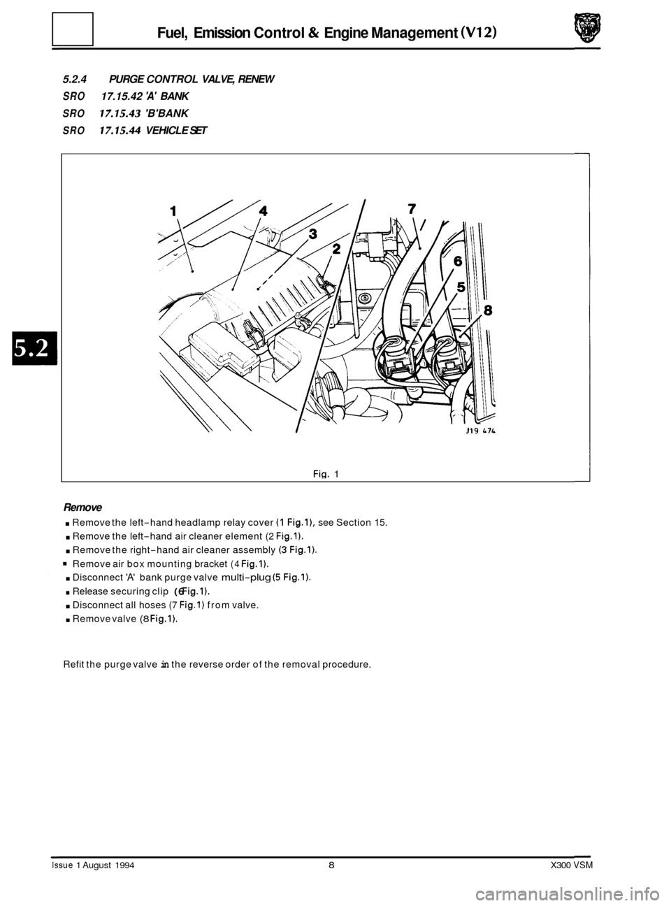
5.2.4 PURGE CONTROL VALVE, RENEW
SRO 17.15.42 'A' BANK
SRO 17.15.43 'B'BANK
SRO 17.15.44 VEHICLE SET
Fig. 1
Remove
. Remove the left-hand headlamp relay cover (1 Fig.l), see Section 15.
. Remove the left-hand air cleaner element (2 Fig.1).
. Remove the right-hand air cleaner assembly (3 Fig.1).
Remove air box mounting bracket (4 Fig.1).
. Disconnect 'A' bank purge valve multi-plug (5 Fig.1).
. Release securing clip (6 Fig.1).
. Disconnect all hoses (7 Fig.1) from valve.
. Remove valve (8 Fig.1).
Refit the purge valve in the reverse order of the removal procedure.
Issue 1 August 1994 8 X300 VSM
Page 116 of 521

Manual Transmission & clutch (AJ16)
I Molykote FB 180 grease
Brake (clutch) fluid
- minimum
DOT 4
Dexron IID Transmission oil
Loctite
573
Tivoli Kay Adhesives No. 5696
Withdrawal arm pivots / Gearshift lever ball
Clutch hydraulic system
Front cover securing bolts
Exhaust sealer also used
in
ZF automatic
transmissions
Application
Material removal to clean up clutch face
IU SERVICE DATA
Specification
Up to lmm maximum
X300 VSM iii Issue 1 August 1994
Page 119 of 521

Manual Transmission & Clutch (AJ16)
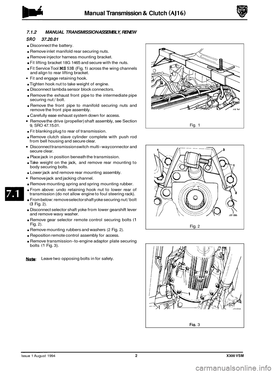
7.1.2 MANUAL TRANSMISSION ASSEMBLY, RENEW
SRO 37.20.01
. Disconnect the battery.
. Remove inlet manifold rear securing nuts.
. Remove injector harness mounting bracket.
. Fit lifting bracket 18G 1465 and secure with the nuts.
. Fit Service Tool MS 536 (Fig. 1) across the wing channels
Fit and engage retaining hook.
. Tighten hook nut to take weight of engine.
. Disconnect lambda sensor block connectors.
. Remove the exhaust front pipe to the intermediate pipe
securing nut / bolt.
. Remove the front pipe to manifold securing nuts and
remove the front pipe assembly.
. Carefully ease exhaust system down for access.
Remove the drive (propeller) shaft assembly, see Section
. Fit blanking plug to rear of transmission.
. Remove clutch slave cylinder complete with push rod
Disconnect transmission switch multi-way connector and
. Place jack in position beneath the transmission.
. Take weight on the jack, and remove rear mounting to
. Lower jack and remove rear mounting assembly.
Remove jack and jacking channel.
. Remove mounting spring and spring mounting rubber.
. From above: undo retaining hook nut to lower rear of
transmission (do not allow engine to foul steering rack).
. From below: remove selector shaft yoke securing nut / bolt (3 Fig. 2).
. Disconnect selector shaft yoke from lower gearshift lever
and remove wavy washer.
. Remove gear selector remote control securing bolts (1 Fig. 2).
. Remove mounting rubbers and washers (2 Fig. 2).
. Reposition remote control assembly for access.
. Remove transmission-to-engine adaptor plate securing
and
align to rear lifting bracket.
9, SRO 47.15.01.
from bell housing and secure clear.
secure clear.
body securing bolts.
bolts
(1 Fig. 3).
N.&: Leave two opposing bolts in for safety.
Fig. 1
Fig.
2
Fig. 3 ~ ~ ~~ ~
Issue 1 August 1994 2 X300 VSM
Page 120 of 521

Manual Transmission & Clutch (AJ16)
. Remove front clamp from unit lift.
. Raise / lower unit with jack, no stands.
. Traverse lift under ramp and take weight of transmission.
. Adjust jacking platform angles to suit transmission.
. Adjust side and rear clamps to suit transmission and tighten clamp wing nuts.
. Fit the safety chain assembly to left hand arm of lift, and secure with peg.
Pass safety chain over transmission and engage in front arm of lift. Tighten the safety chain adjuster.
. Remove remaining transmission to adaptor plate securing bolts and carefully lower transmission from engine.
. Remove transmission from ramp area.
. Remove clutch release bearing assembly from release lever.
. Remove clutch release lever retaining clip and remove lever.
. Remove release lever pivot pin.
Remove transmission switch.
. Remove rear mounting spring retainer securing nut.
. Reposition selector shaft pin cover.
0
Remove rear mounting spring retainer and remove rear mounting assembly.
Remove selector shaft yoke to selector shaft retaining pin and remove the yoke.
. Remove slave cylinder securing studs.
. Remove the transmission from the unit lift.
. Remove transmission drain plug and allow to drain, refit
the drain plug.
Fit new transmission to unit lift.
Fill transmission with oil and refit the level plug.
. Clean components and mating faces.
. Fit the slave cylinder mounting studs.
. Lubricate the selector output shaft.
. Fit selector shaft yoke (3 Fig. 1) to selector shaft and secure
with retaining pin (2 Fig. 1).
Reposition the retaining cover (1 Fig. 1) over the selector
shaft yoke retaining pin. -
. Fit the transmission rear mounting assembly and secure
with bolt.
. Fit reverse lamp switch.
. Lubricate the clutch release lever.
. Fit and align lever to transmission and engage onto pivot
pin.
Fit and fully seat lever to pivot retaining clip.
= Lubricate release bearing housing.
9 Fit and fully seat bearing assembly to lever.
. Select third gear.
. Move transmission to vehicle and raise into position.
Fia. 1
. Insert transmission input shaft into clutch and fully seat transmission against adaptor plate, ensuring that trans- mission is in line as it is fitted and seated to the plate.
X300 VSM 3 Issue 1 August 1994
Page 121 of 521

Manual Transmission & clutch (AJ16)
Fit and tighten transmission to adaptor plate securing
. Slacken chain adjuster.
. Release securing peg from adjuster.
. Displace securing chain from the unit lift.
. Slacken clamp from wing nuts.
. Release clamps from transmission.
. Lower lift and traverse aside.
Refit front clamp to unit lift.
. Connect transmission switch and fit multi-way connector
. Clean and lubricate clutch slave cylinder push rod and fit
. Fit slave cylinder to mounting studs and secure with nuts.
Fit and seat remote control mounting rubbers and
. Align remote control assembly to transmission.
. Fit mounting rubber backing washers.
Refit remote control mounting and secure with bolts (1
. Fit wavy washer to gearshift lever.
. Position selector shaft yoke to gearshift lever.
. Apply lubricant to selector shaft yoke / gearshift lever
. Fit and tighten selector shaft yoke to gearshift lever secur-
. From above: Tighten MS 538 hook nut to raise trans-
. Position the jack beneath the transmission.
bolts
(1 Fig. 1).
into
securing clip.
to slave cylinder.
spacers.
Fig.
2).
assembly.
ing nut
/ bolt (3 Fig. 2).
mission into position (Fig. 3).
. Fit spring to rear mounting assembly.
. Fit upper rubber to mounting spring.
Using a jack, fit and seat the mounting assembly to the body / transmission.
. Fit but do not fully tighten mounting securing bolts.
. Lower and remove jack.
. Remove jack channel.
. From above: Fully undo MS 53B hook nut.
. From below: Final align mounting to transmission / body.
. Final tighten the mounting assembly securing bolts.
. Clamp the front exhaust pipe in a vice.
. Remove and discard the front pipe to manifold sealing
. Clean the faces.
Fit and fully seat new rings to pipe.
. Remove the front pipe from the vice and align to the
. Align retaining rings to the studs and secure with the nuts.
rings.
man
ifold.
Fin. 1
Fig.
2
Fig. 3
Issue 1 August 1994 4 X300 VSM
Page 123 of 521

Manual Transmission & Clutch (AJ16)
7.1.4 REAR OIL SEAL, RENEW
SRO 37.23.01
Remove the drive (propeller) shaft, see Section 9, SRO
47.15.01.
. Using a suitable oil seal remover, displace and removethe
rear oil seal (1 Fig. 1).
. Clean the seal mounting face.
. Lubricate the seal lip.
. Fit and seat the seal to the transmission.
. Refit the drive shaft, see 47.15.01.
7.1.5 GEARSHIFT LEVER, RENEW
SRO 37.16.04
. Remove and strip down the gear selector remote control
assembly as detailed in Sub-section 7.1.8.
. Rebuild and refit the gear selector remote control assem- bly (Sub-section 7.1.81, but fit a new replacement gear- shift lever and discard the original lever.
7.1.6 GEARSHIFTLEVER DRAUGHT EXCLUDER,
SRO 37.16.05 RENEW
. Remove
the gearshift lever knob (1 Fig. 2), see Sub-Sec-
. Open the centre console storage compartment.
tion 7.1.7.
= Remove the centre console securing screws, disconnect
Remove the foam sealing ring.
. Remove the draught excluder securing screws (2 Fig. 2)
and ring (3 Fig. 2) and remove the draught excluder (4 Fig.
2).
. Fit the new draught excluder over the gearshift lever and
secure with the ring (3 Fig. 2) and screws (2-Fig. 2).
. Refit the foam sealing ring.
Refit the centre console and reconnect the block
Close the centre console storage compartment.
. Fit the gearshift lever knob/ lock nut and align the knob to
Tighten the lock nut and reposition the gearshift lever
the
block connectors and remove the console.
connectors and secure with the screws.
its final position.
gaiter.
I --0-. I
J37.02~
Fin. 1
Fig. 2
0
0
0
Issue 1 August 1994 6 X300 VSM
Page 124 of 521

Manual Transmission & Clutch (AJ16)
GEARSHIFT LEVER KNOB, RENEW
:RY 37.16.11
. Displace the gearshift lever gaiter for access and slacken
the gearshift lever knob lock nut (1 Fig. 1) and remove the
gearshift lever knob
(2 Fig. 1).
- Fit the new gearshift lever knob and align to its final posi- tion.
. Tighten the lock nut and reposition the gearshift lever
gaiter.
7.1.8 GEARSHIFT LEVER/ REMOTE CONTROL
ASSEMBLY, RENEW
SRO 37.16.20
. Disconnect the battery.
. Remove inlet manifold rear securing nuts.
. Fit lifting bracket 18G 1465 and secure with the nuts.
. Fit Service Tool MS 538 (Fig. 2) across the wing channels
and align to rear lifting bracket.
Fit and engage retaining hook.
. Tighten hook nut to take weight of engine.
Select third gear and remove the gearshift lever knob.
. Disconnect lambda sensor block connectors.
Remove the exhaust front pipe to the intermediate pipe
securing nut / bolt.
. Remove the sealing olive.
. Take the weight of the rear engine mounting using a jack,
. Remove the rear mounting securing bolts.
. Lower and remove the rear mounting assembly.
Carefully ease exhaust system down for access.
jack channel
and a suitable block.
. Remove the drive (propeller) shaft assembly, see Section 9, SRO 47.15.01.
. From above: undo retaining hook nut to lower rear of
transmission (do not allow engine to foul steering rack).
From below: slacken but do not remove the selector shaft
bolt
(3 Fig. 3).
. Remove the gear selector remote control securing bolts (1 Fig. 1) and reposition for access.
Finally remove the selector shaft bolt (3 Fig. 3).
. Remove the gear selector remote control assembly from
the selector shaft.
b: To aid removal, invert the gear selector remote con- trol assembly, i.e. gearshift lever pointing down- wards.
2
Fig. 1
Fig. 2
Fig. 3
X300 VSM 7 Issue 1 August 1994