1994 JAGUAR XJ6 SRS
[x] Cancel search: SRSPage 102 of 327

Electrical IT
SECTION CONTENTS
Sub
-Section 15.2 lnsfrumenfs
Subsection Title SRO Page
15.2 ............. Instruments .................................................................... 15.2-1
15.2.1
............ Introduction .................................................................... 15.2-1
15.2.2
............ Instrument Pack Connectors - Pin Locations ......................................... 15.2-3
15.2.3
............ Component Description .......................................................... 15.24
15.2.3.1 .......... Speedometer ................................................................... 15.24
15.2.3.2 .......... Tachometer .................................................................... 15.24
15.2.3.3
.......... Engine Oil Pressure and Warning Lamp ............................................. 15.24
15.2.3.4 .......... Engine Coolant Temperature ...................................................... 15.24
15.2.3.5 .......... Fuel Tank Level Gauge and Warning Lamp .......................................... 15.24
15.2.3.6
.......... Battery Voltage Gauge and Warning Lamp .......................................... 15.24
15.2.3.7
.......... Liquid Crystal Display ........................................................... 15.24
15.2.3.8 .......... Trip Computer .................................................................. 15.2-5
15.2.4
............ Primary Warning Lamps (Illuminated Red) .......................................... 15.2-5
15.2.4.1
.......... Exhaust Temperature ............................................................ 15.2-5
15.2.4.2
.......... Low Oil Pressure ................................................................ 15.2-5
15.2.4.3
.......... Seat Belt ....................................................................... \
15.2-5
15.2.4.4
.......... Trunk Lid Open ................................................................. 15.2-5
15.2.4.5
.......... DoorAjar ...................................................................... 15.2-5
15.2.4.6
.......... Engine Coolant LeveL ............................................................ 15.24
15.2.4.7
.......... SRS Airbag Fault ................................................................ 15.24
15.2.4.8 .......... Charging Fault .................................................................. 15.24
15.2.4.9 .......... Brake System Fault .............................................................. 15.24
15.2.4.10 ......... Bark Brake ..................................................................... 15.24
15.2.5. ........... Secondary Warning Lamps (Illuminated Amber) ...................................... 15.2-7
15.2.5.1
.......... Transmission Fault ............................................................... 15.2-7
15.2.5.2
.......... Washer Fluid Level .............................................................. 15.2-7
15.2.5.3
.......... Bulb Fail ....................................................................... \
15.2-7
15.2.5.4
.......... Traction Control Fail ............................................................. 15.2-7
15.2.5.5
.......... Anti-lock Fail .................................................................. 15.2-7
15.2.5.6
.......... Low Fuel Level ................................................................. 15.2-7
15.2.5.7
.......... Check Engine ................................................................... 15.2-7
15.2.6.1
.......... Transmission Sport Mode ......................................................... 15.2-8
15.2.6.2
.......... Traction Control OFF ............................................................ 15.2-8
15.2.6.3
.......... Direction Indicators ............................................................. 15.2-8
15.2.6.4
.......... Main Beam .................................................................... 15.2-8
15.2.6
............ Status
and Warning Lamps ........................................................ 15.2-8
m
a
0
e
0
X300 EDM ii Issue 1 August 1994
Page 107 of 327

E I ect r ica I
15.1 SUPPLEMENTAL RESTRAINT SYSTEM
15.1.1 System Description
The Supplemental Restraint System (SRS) installation comprises:
0 electronic Diagnostic Module (DM)
0 driver and passenger-side air bag modules (including firing mechanisms)
0 two front impact sensors (left and right)
0 one safing sensor
0 dedicated wiring harness
0 two cable reel cassettes (integral part of the steering column harness)
0 Malfunction Indicator Lamp (MIL) and driver information message
The system is designed to provide protection for both driver and front seat passenger by automatically deploying air
bags in the event of a collision during forward travel. The driver
-side air bag is located in the centre of the steering
wheel assembly and the passenger-side air bag in the fascia panel.
In the event of a collision the impact
/ safing sensors operate, completing the electrical firing circuit and causing the
air bags to inflate within 32 milliseconds. At least two of the three sensors (at least one impact, and the safing sensor)
.must be activated to initiate firing. System operation is dependent upon battery voltage supplied directly, and via the
ignition switch, to the DM and the correct installation and operation of all system components, including the wiring
harness. Faults in system components, installation or wiring will be indicated by the MIL Lamp, located on the instru
- ment panel, which will illuminate 'SRS AIR BAG'. Indication is also given by the driver information message'AIR BAG'
displayed on the LCD panel below the speedometer.
15.1.2.1 Diagnostic Module (Fig. I)
The Diagnostic Module (DM), mounted below the passenger-side air bag module, behind the console fascia panel, is
the electronic microprocessor unit which monitors the whole SRS system. The state of the three system sensors, two
air bag modules and the wiring harness is monitored constantly to detect activation criteria and component faults.
15.1.2 COMPONENT DESCRIPTIONS
The unit also confirms correct supply conditions by compar- ing a direct battery voltage input with an input, via the igni- tion switch, of the same voltage value. Detection of system
faults will be relayed by the DM to the instrument panel and
the air bag MIL Lamp illuminated.
The DM contains a reserve power supply unit, enabling the
air bagsto fire even if supply voltage is lost during an impact
situation. The reserve power charge will be retained for ap
- proximately one minute after the positive supply voltage is
disconnected. An auxiliary internal circuit, known as the
'dwell enhancer', provides a temporary ground to compen
- sate for damaged primary crash sensors. If either primary
crash sensor operates for 5 milliseconds the 'dwell en- hancer' circuit will turn on, completing the firing circuit to
ground for 90 milliseconds. The purpose of this is to allow
air bag deployment even if the operated primary crash sen- sor circuit is defective or opens.
15.1.2.2 Wiring Harness
Fig. 1
A dedicated wiring harness, covered with yellow sheathing, independent of any other vehicle system, is used to electri- cally connect all the component items. To allow movement of the steering mechanism, two cable reel cassettes are
incorporated into the driver-side air bag module circuitry, as a means of compensating for steering wheel rotation is
required to prevent harness damage or disconnection. The two cable reel cassettes form an interface between the
steering column and air bag module and, due to their coiled construction, are able to contract or expand as required.
15.1.2.3 Air Bag Modules
The two air bag modules, driver and passenger side, are
each activated when either front impact sensor (Fig. 2) and
the safing sensor operate simultaneously. Both modules
contain a charge of sodium
azide/copper oxide which, when
ignited by an electrical impulse, generate a volume of ni
- trogen gassufficientto inflatetheair bag. Theamountof gas
generated is greater in the passenger-side air bag due to its
larger size. Both modules, including surrounding trim pan- els, are non-serviceable and once activated must be re-
newed as a complete assembly.
Fig. 2
X300 EDM 15.1 - 1 Issue 1 August 1994
Page 108 of 327

IT Electrical
15.1.2.4 Impact Sensors
The three impact sensor devices determine when air bag fir- ing is necessary by detecting crash conditions according to
direction of travel and force of movement. An impact of
sufficient force in a forward direction will close contacts in
either one or both of
the front impact sensors, left and right.
When either (or both) of the front sensors contacts are
closed then the impact force must be sufficient to close the
safing sensor contacts also, before air bag firing can com
- mence. The front impact sensors are mounted between
each headlamp mounting bracket and bonnet hinge mount- ing (Fig. 2, previous page), the safing sensor is mounted on
the right-hand side footwell at the base of the 'A' post (Fig.
1). Fig. 1
1.
Driver-side Air Bag Module 6. RH Impact Sensor
2. Cable Reel Cassette 7. Ground 3. Passenger-side Ait Bag Module 8. Rear Safing Sensor 4. Diagnostic Module 9. Cabin Harness Connector
5. LH Impact Sensor
Fig.
2 SRS System Schematic
Issue 1 August 1994 15.1 - 2 X300 EDM
Page 109 of 327
Electrical rl
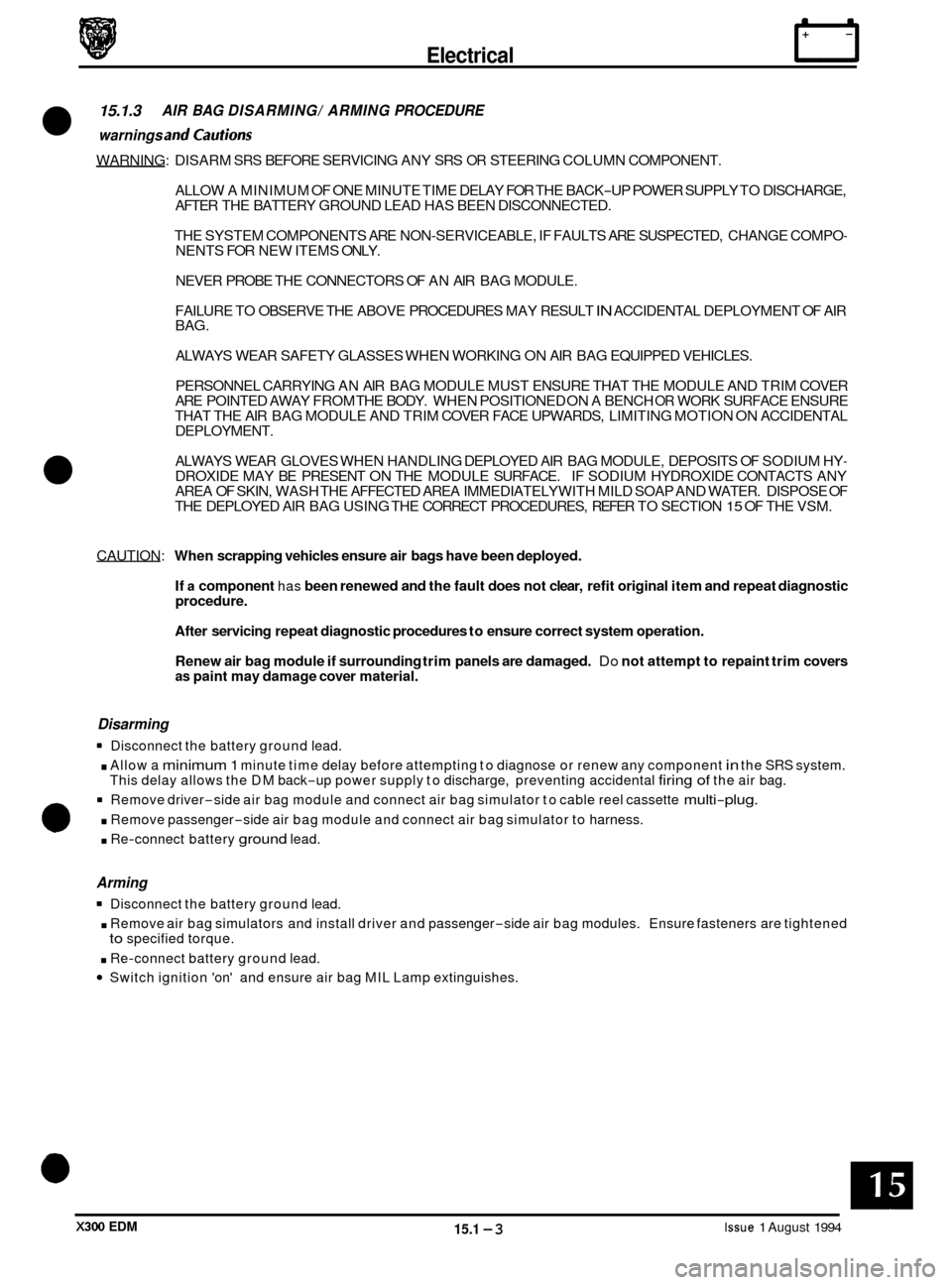
15.1.3 AIR BAG DISARMING/ ARMING PROCEDURE
warnings and cautions
WARNING: DISARM SRS BEFORE SERVICING ANY SRS OR STEERING COLUMN COMPONENT.
ALLOW A MINIMUM OF ONE MINUTE TIME DELAY FOR THE BACK
-UP POWER SUPPLY TO DISCHARGE,
AFTER THE BATTERY GROUND LEAD HAS BEEN DISCONNECTED.
THE SYSTEM COMPONENTS ARE NON
-SERVICEABLE, IF FAULTS ARE SUSPECTED, CHANGE COMPO- NENTS FOR NEW ITEMS ONLY.
NEVER PROBE THE CONNECTORS OF AN AIR BAG MODULE.
FAILURE TO OBSERVE THE ABOVE PROCEDURES MAY RESULT
IN ACCIDENTAL DEPLOYMENT OF AIR
BAG.
ALWAYS WEAR SAFETY GLASSES WHEN WORKING ON AIR BAG EQUIPPED VEHICLES.
PERSONNEL CARRYING AN AIR BAG MODULE MUST ENSURE THAT THE MODULE AND TRIM COVER
ARE POINTED AWAY FROM THE BODY. WHEN POSITIONED ON A BENCH
OR WORK SURFACE ENSURE
THAT THE AIR BAG MODULE AND TRIM COVER FACE UPWARDS, LIMITING MOTION ON ACCIDENTAL
DEPLOYMENT.
ALWAYS WEAR GLOVES WHEN HANDLING DEPLOYED AIR BAG MODULE, DEPOSITS OF SODIUM HY
- DROXIDE MAY BE PRESENT ON THE MODULE SURFACE. IF SODIUM HYDROXIDE CONTACTS ANY
AREA OF SKIN, WASH THE AFFECTED AREA IMMEDIATELY WITH MILD SOAP AND WATER. DISPOSE OF
THE DEPLOYED AIR BAG USING THE CORRECT PROCEDURES, REFER TO SECTION
15 OF THE VSM.
CAUTION:
When scrapping vehicles ensure air bags have been deployed.
If
a component has been renewed and the fault does not clear, refit original item and repeat diagnostic
procedure.
After servicing repeat diagnostic procedures to ensure correct system operation.
Renew air bag module if surrounding trim panels are damaged.
Do not attempt to repaint trim covers as paint may damage cover material.
Disarming
. Allow a minimum 1 minute time delay before attempting to diagnose or renew any component in the SRS system.
Remove driver-side air bag module and connect air bag simulator to cable reel cassette multi-plug.
. Remove passenger-side air bag module and connect air bag simulator to harness.
. Re-connect battery ground lead.
Disconnect
the battery ground lead.
This delay allows the DM back
-up power supply to discharge, preventing accidental firing of the air bag.
0
Arming
Disconnect the battery ground lead.
. Remove air bag simulators and install driver and passenger-side air bag modules. Ensure fasteners are tightened
. Re-connect battery ground lead.
Switch ignition 'on' and ensure air bag MIL Lamp extinguishes.
to specified torque.
X300 EDM 15.1 -3 Issue 1 August 1994
Page 110 of 327

Electrical n
15.1.4 DIAGNOSTICMODULE FAULT CODES
Fault codes can be extracted in one of two ways:
Through the
IS0 Communication Bus using Jaguar Diagnostic equipment.
As a series of flashes using the SRS Service Tool.
Each series offlashes represents a two digit number, representing the fault code. For example fault code
24 is displayed
as:
Two flashes, a one second pause, four flashes, three second pause. Then repeated.
All fault codes are listed in order of priority.
Page 112 of 327

Electrical
0
NO AIR BAG MIl LAMP
Inoperative lamp Circuit or No Ignition to the Diagnostic Module
Normal Operation
The air bag MIL Lamp is designed to illuminate for approximately six seconds when the ignition is switched ‘on’; this
time has been allocated to prove the MIL Lamp operation.
The DM requires an ignition supply to Pin
1, to energize the air bag MIL Lamp circuit. If the MIL Lamp is open circuit
or the DM does not receive ignition voltage at Pin 1, the MII Lamp will not illuminate.
Open circuit in the
MII Lamp supply will cause the DM to emit five tones, or ‘beeps’ every 30 minutes while ignition
is on. Repair faulty circuitry before further diagnostics.
Possible Causes
0 Bulb blown or faulty wiring in the air bag MIL Lamp circuit.
0 Loss of ignition voltage at DM pin 1.
Fault Diagnosis
1. Ignition voltage -check
8 Disarm the SRS system.
8 Switch on the ignition.
8 Measure the voltage between pin 1 (+vel and pin 3 (-vel of the connector.
8 Battery voltage present, proceed with step 2.
8 Battery voltage not present; open circuit on R / W wire from RH fuse-box or faulty ground at pin 3.
8 Check fuse 17, RH fuse-box.
8 Check the fuse connectors and wiring.
8 Check the ground at pin 3 of the DM connector.
8 Arm and verify the SRS system.
2. MIL Lamp open circuit
8 Renew the DM.
8 Arm and verify the SRS system.
If the MIL Lamp is not illuminated, check the bulb, instrument pack and associated wiring.
Issue 1 August 1994 15.1 - 6 X300 EDM
Page 114 of 327

rl E I ect r ica I
CONTINUOUS AIR BAG MIL LAMP ILLUMINATION
Inoperative Lamp Circuit or No Ignition to the Diagnostic
Module
Normal Operation
The air bag MIL Lamp is designed to illuminate for approximately six seconds when the ignition is switched 'on'; this
time has been allocated to prove the MIL Lamp operation. If, after this proving period, the DM detects faults within
the system the MIL Lamp will illuminate and 'AIR BAG' will be displayed to the driver. If the MIL Lamp remains ON constantly, for over 8 seconds after ignition switch on, a fault is present within the indicator circuit.
Poor connection, or disconnection, of the indicator harness will cause
a short between pins 4 and 5, connecting the
circuit to ground and giving constant illumination of the MIL Lamp.
Faulty operation
ofthe DM internal logic may fail to turn off the indicator control circuit and cause constant illumination
of the MIL Lamp.
Fault Diagnosis
1. DM connectors
8 Disarm the SRS system.
8 Inspect the DM connectors.
2. MIL Lamp short circuit.
8 Disconnect the DM.
8 Remove the plastic locking wedge from the grey DM connector.
Switch on the ignition.
8 If the MIL Lamp is not illuminated, go to step 3.
If the MIL Lamp is illuminated; short circuit to ground between pin 45 instrument pack to pin 4 DM (Y / W). Rectify
8 Arm and verify the SRS system.
the short circuit.
3. Shorting
bar
Is the connector shorting bar operating correctly ?
Yes -
8 Renew the DM.
Reconnect, arm and verify the SRS system.
8 Renew the plastic locking wedge.
. Reconnect, arm and verify the SRS system.
NO -
15.1 -8 X300 EDM Issue 1 August 1994
Page 116 of 327

n E I ectr ica I
FAULT CODE 12
Low Battery Voltage
Normal Operation
The DM monitors voltage at pin 13 which should be equal to battery voltage. If a voltage lower than 9V is detected at pin 13 the MIL Lamp will illuminate and fault code 12 will be present.
Possible Causes
Drop in battery voltage to DM pin 13 caused by:
0 Open circuit to pin 13 from battery.
0 Short circuit to ground on battery feed circuit.
0 Safing sensor feed shorted to ground.
0 Safing sensor internal short to ground.
0 Faulty charging system draining battery voltage.
Fault Oiagnosis
1. Battery voltage test
Disarm the SRS system.
8 Disconnect the DM.
8 Switch on the ignition.
Measure the voltage between DM connector pin 13 (+ve) and pin 3(-ve).
If battery voltage is present at pin 13, renew the DM.
8 Arm and verify the SRS system.
8 If battery voltage is not present, go to step 2.
2.
Fusecheck
8 Check fuse 17 in the RH fuse-box.
If the fuse has blown, check for short circuit to ground between fuse and pin 13 DM connector.
8 Renew the fuse, go to step 3.
8 If the fuse has not blown, check for open circuit between battery positive terminal and pin 13 DM connector.
3. Short circuit check
* Switch off the ignition.
8 Connect the DM.
8 Has the fuse blown 1
Yes -
= Short circuit to ground from pin 15 DM (R/ W) to pin 3 safing sensor, or from pin 23 DM (Y / P) to pin 6 safing sensor.
8 Intermittent short circuit to ground; check wire (R / W) from pin 15 DM to pin 3 safing sensor, and, wire (Y/ P) from
NO -
pin 23 DM to pin 6 safing sensor.
4. On completion
8 Renew the fuse as necessary.
8 Arm and verify the SRS system.
Issue 1 August 1994 15.1 - 10 X300 EDM