1994 JAGUAR XJ6 lock
[x] Cancel search: lockPage 103 of 327

Electrical IT
SECTION CON TENTS
Subsection 15.2 Instruments (continued)
Sub-Section Title SRO Page
15.2.7 ............ Fault Diagnosis ................................................................. 15.2-9
15.2.7.1
.......... Active High /Low Inputs ......................................................... 15.2-9
15.2.8.
........... Instrument Pack Pin-point Tests .................................................. 15.2-1 0
15.2.8.1 .......... Oil Pressure, Battery Condition, Coolant Temperature and Fuel Gauges ................. 15.2-1 0
75.2.8.2
.......... Speedometer .................................................................. 15.2-10
15.2.8.4
.......... Liquid Crystal Display .......................................................... 15.2-17
15.2.8.6
.......... Door Open Warning Lamp ...................................................... 15.2-12
15.2.8.7
.......... Exhaust Temperature Warning Lamp .............................................. 15.2-1 3
15.2.8.8 .......... Luggage Compartment Warning Lamp ............................................. 15.2-14
15.2.8.9
.......... Seat Belt Warning Indicator ...................................................... 15.2-1 5
15.2.8.3
.......... Tachometer ................................................................... 15.2-11
15.2.8.5
.......... Trip Computer ................................................................. 15.2-11
15.2.8.70
......... Park Brake Indicator ............................................................ 15.2-16
15.2.8.71
......... Main Beam Indicator ........................................................... 15.2-17
75.2.8.12
......... Direction Indicator Tell Tales ..................................................... 15.2-18
15.2.8.14
......... Washer Fluid Level Indicator ..................................................... 15.2-20
15.2.8.16
......... Brake Fluid Level Indicator ...................................................... 15.2-22
75.2.8.17
......... General Bulb Failure Indicator ................................................... 15.2-23
15.2.8.18
.........
75.2.8.19 .........
15.2.8.20 ......... Traction Control OFF Tell-tale .................................................... 15.2-24
0
75.2.8.13 ......... Generator IND Voltage Indicator ................................................. 15.2-19
7 5.2.8.15 ......... Engine Coolant Level indicator ................................................... 15.2-2 1
Transmission Sport mode Indicator ................................................ 75.2-24
Traction Control Failure Warning Lamp
............................................ 15.2-24
15.2.8.21
......... Anti-lock Failure Warning Lamp .................................................. 15.2-24
15.2.8.22
......... Check Engine Warning Lamp .................................................... 75.2-24
Issue 1 August 1994 iii X300 EDM
Page 114 of 327

rl E I ect r ica I
CONTINUOUS AIR BAG MIL LAMP ILLUMINATION
Inoperative Lamp Circuit or No Ignition to the Diagnostic
Module
Normal Operation
The air bag MIL Lamp is designed to illuminate for approximately six seconds when the ignition is switched 'on'; this
time has been allocated to prove the MIL Lamp operation. If, after this proving period, the DM detects faults within
the system the MIL Lamp will illuminate and 'AIR BAG' will be displayed to the driver. If the MIL Lamp remains ON constantly, for over 8 seconds after ignition switch on, a fault is present within the indicator circuit.
Poor connection, or disconnection, of the indicator harness will cause
a short between pins 4 and 5, connecting the
circuit to ground and giving constant illumination of the MIL Lamp.
Faulty operation
ofthe DM internal logic may fail to turn off the indicator control circuit and cause constant illumination
of the MIL Lamp.
Fault Diagnosis
1. DM connectors
8 Disarm the SRS system.
8 Inspect the DM connectors.
2. MIL Lamp short circuit.
8 Disconnect the DM.
8 Remove the plastic locking wedge from the grey DM connector.
Switch on the ignition.
8 If the MIL Lamp is not illuminated, go to step 3.
If the MIL Lamp is illuminated; short circuit to ground between pin 45 instrument pack to pin 4 DM (Y / W). Rectify
8 Arm and verify the SRS system.
the short circuit.
3. Shorting
bar
Is the connector shorting bar operating correctly ?
Yes -
8 Renew the DM.
Reconnect, arm and verify the SRS system.
8 Renew the plastic locking wedge.
. Reconnect, arm and verify the SRS system.
NO -
15.1 -8 X300 EDM Issue 1 August 1994
Page 120 of 327

Electrical I3
FAULTCODE 14
Front Impact Sensor Circuit Shorted to Ground
Normal Operation
The DM monitors voltage level at pins 2 and 6. If this voltage falls to 5 volts, or less, the MIL Lamp will illuminate and
fault code 14 will be present, indicating a short circuit to ground on either of the two front impact sensorcircuits. During
the presence of fault code 14 the DM internal thermal fuse will blow, disabling the air bag deployment circuit. If voltage
to pins
2 and 6 is restored after the fuse has blown,fault code 51, open internal fuse will be present. Fault code 14 will
be present only as long as the short to ground remains.
Possible Causes
Short to ground in any of the following circuits:
0 Front impact sensor wiring.
0 Disconnection, or poor connection of harness.
0 Front impact sensors internal ground.
Fault Diagnosis
1. Sub-circuit identification
. Disarm SRS system.
. Remove plastic locking wedge from the grey DM connector.
. Measure resistance between connector pin 3 and all of the following pins; 2,6, 17 and 18.
9 Does any resistance reading indicate short circuit ?
Yes - Renew faulty sensor.
No - Examine sensor wiring harness, locate and rectify faults as necessary.
Proceed to fault code 51 on successful diagnosis.
rm
0
0
0
0
X300 EDM Issue 1 August 1994 15.1 - 14
Page 130 of 327

rl Electrical
FAULT CODE 32
Driver-side Air Bag Circuit High Resistance or Open
Normal Operation
The DM monitors the resistance between pins 10 and 11. The value of this resistance is the sum of the two cable reel
cassettes, the air bag and is normally between
1.5~2 and 2Q. If the resistance measured exceeds 4Q the MIL Lamp will illuminate and fault code 32 will be present, indicating high resistance or open circuit on the air bag circuit.
Possible Causes
0 Poor connections or corrosion at clockspring / main harness connections.
0 Open circuit or high resistance of cable reel cassettes.
0 Open circuit or high resistance in driver-side air bag.
0 Faulty driver-side air bag wiring.
Fault Diagnosis
1. Circuit - check
. Disarm SRS system and disconnect DM.
Disconnect DM and remove plastic locking wedge from black DM harness connector.
. Measure resistance across harness connections to passenger air bag, wires KN and RF!
. Is resistance value less than 2Q ?
Yes -
. Ensure locking wedge has been removed correctly from black connector.
. Examine harness for broken, dirty or incorrectly seated connections.
. Rectify faults as necessary.
No - Proceed to step 2.
2. Resistance -check
. Is resistance measured in step 1 greater than 352 7
Yes - Proceed to step 4.
No - Proceed to step 3.
3. Fault code verification
. Reconnect DM and check if code 32 is still present.
Yes
- Renew DM.
No - Examine harness or broken, dirty or incorrectly seated connections. Rectify faults as necessary.
4. Resistance -check
. Disconnect cable reel cassette at base of steering column.
Install air bag simulator (ensure 2Q resistance of simulator before connection) in place of cable reel cassette.
Measure resistance across harness connections to air bag, wires KIN and RI?
Is resistance equal to between 1.m and 2.2Q 7
Yes - Renew cable reel cassette.
No - Examine harness wiring for open circuit, rectify faults as necessary.
5. On completion.
. Arm and verify the SRS system.
0
0
0
0
Issue 1 August 1994 15.1 - 24 X300 EDM
Page 132 of 327

Electrical rl
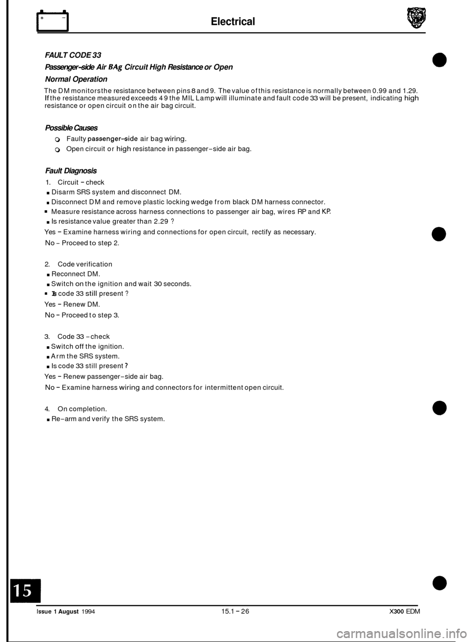
FAULT CODE 33
Passenger-side Air BAg Circuit High Resistance or Open
Normal Operation
The DM monitors the resistance between pins 8 and 9. The value of this resistance is normally between 0.99 and 1.29. If the resistance measured exceeds 49 the MIL Lamp will illuminate and fault code 33 will be present, indicating high resistance or open circuit on the air bag circuit.
Possible Causes
0 Faulty passenger-side air bag wiring.
0 Open circuit or high resistance in passenger-side air bag.
Fault Diagnosis
1. Circuit - check
. Disarm SRS system and disconnect DM.
. Disconnect DM and remove plastic locking wedge from black DM harness connector.
Measure resistance across harness connections to passenger air bag, wires RP and KP:
. Is resistance value greater than 2.29 ?
Yes - Examine harness wiring and connections for open circuit, rectify as necessary.
No - Proceed to step 2.
2. Code verification
. Reconnect DM.
. Switch on the ignition and wait 30 seconds.
Yes
- Renew DM.
No - Proceed to step 3.
Is code 33 still present ?
3. Code 33 -check
. Switch off the ignition.
. Arm the SRS system.
. Is code 33 still present 7
Yes - Renew passenger-side air bag.
No - Examine harness wiring and connectors for intermittent open circuit.
4. On completion.
. Re-arm and verify the SRS system.
rm
0
0
0
0
Issue 1 August 1994 15.1 - 26 X300 EDM
Page 134 of 327

rl E I ect r ica I
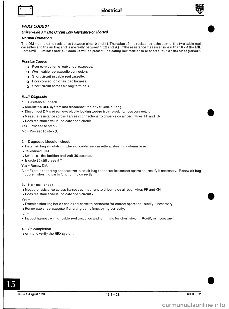
FAULT CODE 34
Driver-side Air Bag Circuit Low Resistance or Shorted
Normal Operation
The DM monitors the resistance between pins 10 and 11. The value of this resistance is the sum of the two cable reel
cassettes and the air bag and is normally between 1.552 and 2Q. If the resistance measured is less than 0.752 the MIL Lamp will illuminate and fault code 34 will be present, indicating low resistance or short circuit on the air bag circuit.
Possible Causes
0 Poor connection of cable reel cassettes.
0 Worn cable reel cassette connectors.
0 Short circuit in cable reel cassette.
0 Poor connection of air bag harness.
0 Short circuit across air bag terminals.
Fault Diagnosis
1. Resistance - check
. Disarm the SRS system and disconnect the driver-side air bag.
rn Disconnect DM and remove plastic locking wedge from black harness connector.
. Measure resistance across harness connections to driver-side air bag, wires RP and KN.
. Does resistance value indicate open circuit.
Yes
- Proceed to step 2.
No - Proceed to step 3.
2. Diagnostic Module -check
Install air bag simulator in place of cable reel cassette at steering column base.
. Re-connect DM.
. Switch on the ignition and wait 30 seconds.
rn Is code 34 still present ?
Yes - Renew DM.
No - Examine shorting bar on driver-side air bag connector for correct operation, rectify if necessary. Renew air bag
module if shorting bar is functioning correctly.
3. Harness -check
. Measure resistance across harness connections to driver-side air bag, wires RP and KN.
. Does resistance value indicate open circuit 7
Yes -
. Examine shorting bar on cable reel cassette connector for correct operation, rectify if necessary.
. Renew cable reel cassette if shorting bar is functioning correctly.
NO -
Inspect harness wiring, cable reel cassettes and terminals for short circuit. Rectify as necessary.
4. On completion
. Arm and verify the SRS system.
Page 136 of 327

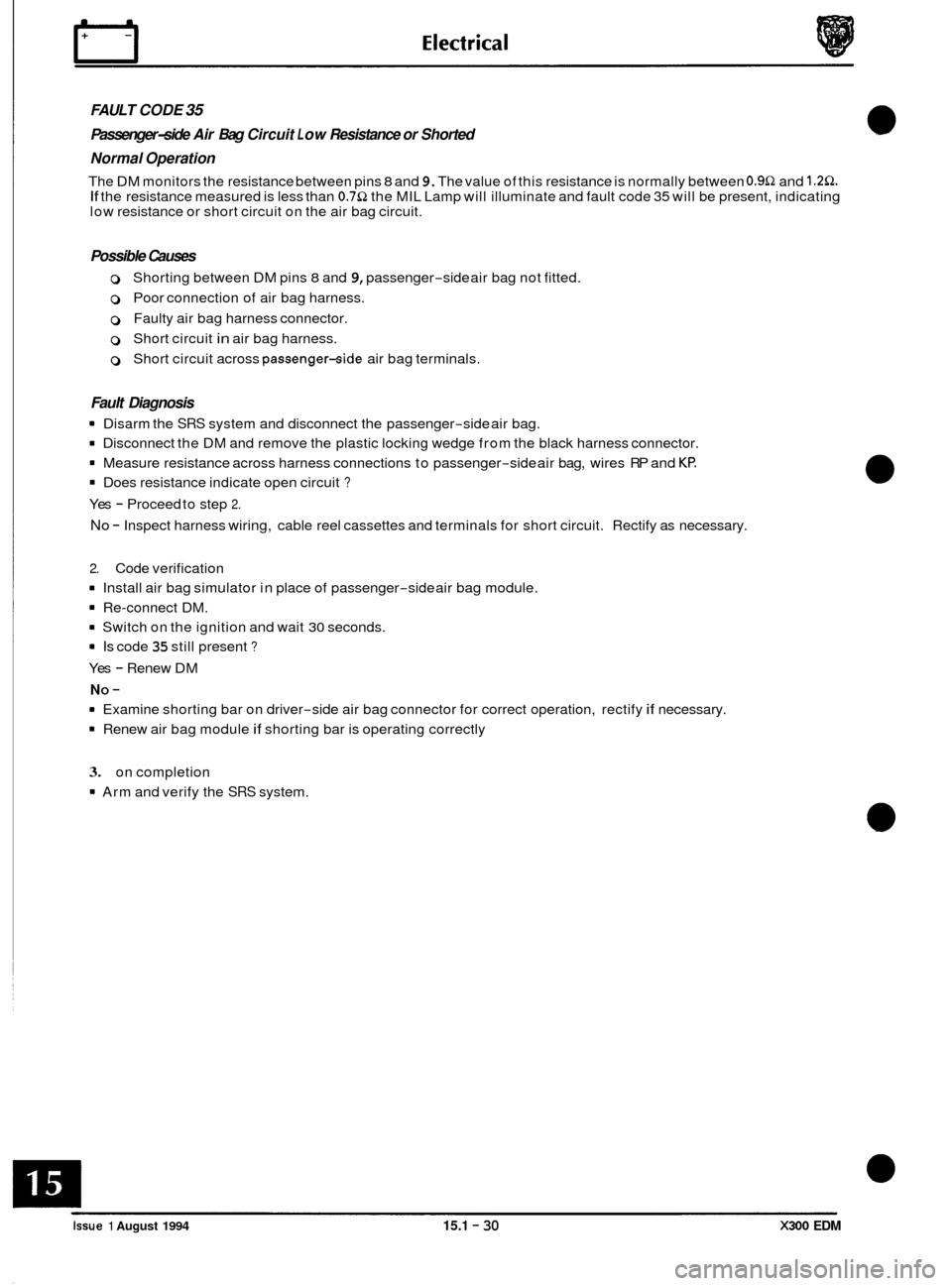
FAULT CODE 35
Passenger-side Air Bag Circuit L o w Resistance or Shorted
Normal Operation
The DM monitors the resistance between pins 8 and 9. The value of this resistance is normally between 0.9Q and 1.2Q. If the resistance measured is less than 0.7Q the MIL Lamp will illuminate and fault code 35 will be present, indicating
low resistance or short circuit on the air bag circuit.
Possible Causes
0 Shorting between DM pins 8 and 9, passenger-side air bag not fitted.
0 Poor connection of air bag harness.
0 Faulty air bag harness connector.
0 Short circuit in air bag harness.
0 Short circuit across passenger-side air bag terminals.
Fault Diagnosis
8 Disarm the SRS system and disconnect the passenger-side air bag.
8 Disconnect the DM and remove the plastic locking wedge from the black harness connector.
8 Measure resistance across harness connections to passenger-side air bag, wires RP and Kf?
8 Does resistance indicate open circuit ?
Yes - Proceed to step 2.
No - Inspect harness wiring, cable reel cassettes and terminals for short circuit. Rectify as necessary.
2. Code verification
8 Install air bag simulator in place of passenger-side air bag module.
8 Re-connect DM.
8 Switch on the ignition and wait 30 seconds.
8 Is code 35 still present ?
Yes - Renew DM
8 Examine shorting bar on driver-side air bag connector for correct operation, rectify if necessary.
8 Renew air bag module if shorting bar is operating correctly
NO -
3. on completion
8 Arm and verify the SRS system.
0
0
e
0
Issue 1 August 1994 15.1 - 30 X300 EDM
Page 150 of 327

rl Electrical
FAULT CODE 53
Front Impact Sensor Circuits Resistance to Ground or Internal Diagnostic Monitor Failure
Normal Operation
The DM measures the voltage on pins 2,6,17 and 18. If there is any resistance to ground on any of these pins or across
the front impact sensors contacts, it will cause the diagnostic voltage on these pins to drop below normal levels. If the
DM measures voltage drop to between 5 and 10 volts, the DM senses an internal voltage regulation failure and code
53 will be present.
A direct short to ground in the front impact sensor circuits
will drop the voltage to less than 5 volts and code 14 will
be present.
!!IQ&: The DM also performs several system self-tests every ignition cycle. If any of these tests fail, fault code 53 will
be present.
Fault Diagnosis
1. System verification
. Disarm the SRS system.
. Disconnect the battery ground lead, allow one minute for DM back-up power to drain.
. Disconnect the DM.
Remove the plastic locking wedge from the grey harness multi-plug connector.
= Measure the resistance between pin 3 (ground) and the following circuits:
. Pin2(ON)
. Pin 6 (VU)
. Pin 17 (KU)
* Pin 18 (KG)
. Are all circuit readings infinite (open circuit) ?
Yes - Renew DM.
No
- Proceed to step 2.
2.
. Using schematic, identify suspect sensor and circuitry.
. Disconnect the suspect sensor.
9 Measure the resistance across the normally open contacts.
. Is the resistance reading infinite (open circuit) ?
Yes - Locate and rectify short to ground on low resistance circuit.
No - Renew front impact sensor.
Impact
sensor open circuit
- check
0
0
e
0
Issue 1 August 1994 15.1 - 44 X300 EDM