1994 JAGUAR XJ6 fuse box
[x] Cancel search: fuse boxPage 187 of 327

rl E I ect r ica I
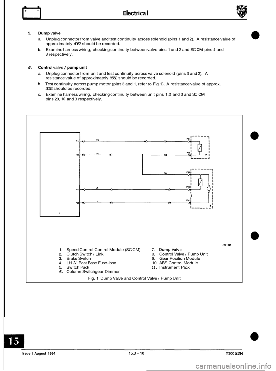
5. Dump valve
a.
b.
Unplug connector from valve and test continuity across solenoid (pins 1 and 2). A resistance value of
approximately 4052 should be recorded.
Examine harness wiring, checking continuity between valve pins 1 and
2 and SC CM pins 4 and
3 respectively.
6. Control valve / pump unit
a. Unplug connector from unit and test continuity across valve solenoid (pins 3 and 2). A
resistance value of approximately 8552 should be recorded.
b. Test continuity across pump motor (pins 3 and 1, refer to Fig 1). A resistance value of approx.
2052 should be recorded.
c. Examine harness wiring, checking continuity between unit pins 1,2 and 3 and SC
CM
pins 20, 10 and 3 respectively.
I Ii
1
1. Speed Control Control Module (SC CM) 7. Dumpvalve
2. Clutch Switch / Link 8. Control Valve / Pump Unit
3. Brake Switch 9. Gear Position Module
4. LH 'A' Post Base Fuse-box 10. ABS Control Module
5. Switch Pack
11. Instrument Pack 6. Column Switchgear Dimmer
Fig. 1 Dump Valve and Control Valve
/ Pump Unit
0
0
0
0
Issue 1 August 1994 15.3 - 10 X300 EDM
Page 188 of 327

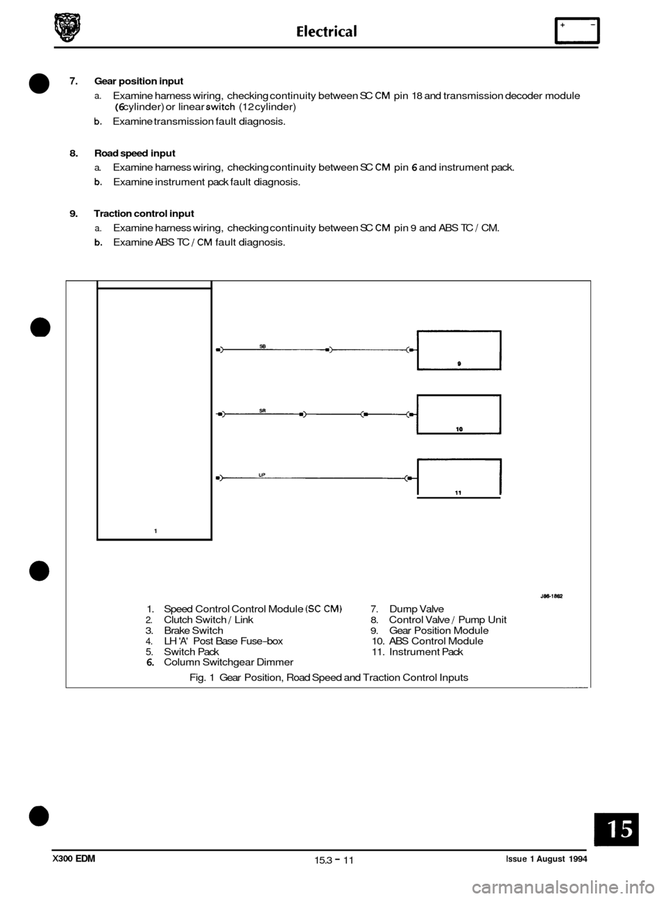
7. Gear position input
a. Examine harness wiring, checking continuity between SC CM pin 18 and transmission decoder module
(6 cylinder) or linear switch (12 cylinder)
b. Examine transmission fault diagnosis.
8. Road speed input
a. Examine harness wiring, checking continuity between SC CM pin 6 and instrument pack.
b. Examine instrument pack fault diagnosis.
9. Traction control input
a.
b.
Examine harness wiring, checking continuity between SC CM pin 9 and ABS TC J CM.
Examine ABS TC
J CM fault diagnosis.
1
1. Speed Control Control Module (SC CM) 7. Dump Valve
2. Clutch Switch J Link 8. Control Valve / Pump Unit
3. Brake Switch
9. Gear Position Module 4. LH 'A' Post Base Fuse-box 10. ABS Control Module
5. Switch Pack 11. Instrument Pack 6. Column Switchgear Dimmer
Fig. 1 Gear Position, Road Speed and Traction Control Inputs
Issue 1 August 1994 15.3 - 11 X300 EDM
Page 214 of 327

Electrical rl
15.4.8 DlAG NOSTIC SUB-ROU T1 NES
0
The following information details possible fault conditions, causes and remedies. Detail test procedures for compo-
nents are covered in 'PIN-POINT TESTS' (Sub-Section 15.4.9).
Fault:
Possible causes:
Remedy:
Fault: Possible causes:
Remedy:
0
Fault:
Possible causes:
Remedy:
Fault:
Possible causes:
Remedy: Driver's
seat adjustment inoperative
1.
2.
3. Mechanical mechanism fault.
1.
2.
3.
No power supply to SCM.
Wiring harness or connectors faulty.
Check fuses
in 'A' post base fuse boxes.
Check harness and connectors between
SCM -fuse box,
SCM
-switch pack and SCM - motors.
Identify and repair mechanical faults.
Seat positional adjustment restricted
1.
2. Motor faulty.
3. Switch faulty.
4. Mechanical mechanism fault.
5. SCM faulty.
1.
2. Renew motor.
3. Renew switch pack.
4.
5. SCM faulty.
Harness
wiring or connector fault.
Examine wiring and connectors between SCM
- switch
pack and SCM
- motors.
Identify and repair mechanical faults.
Seat lumbar pump only inoperative
1.
2.
3. Motor faulty.
4. Switch faulty.
5. Mechanical mechanism
fault.
1.
2.
3. Renew motor.
4. Renew switch.
5. No
power supply to SCM.
Harness wiring or connector fault.
Check fuses in
'A' post base fuse boxes.
Examine wiring and connectors between SCM
- switch
pack and SCM
- motors.
Identify and repair mechanical faults.
Seat heaters only inoperative
1.
2.
3. Heater element faulty.
4. Heater thermostat faulty.
5. Heater switch faulty.
6. Body processor signal fault.
1.
2.
3.
4. Renew faulty switch.
5.
No power supply to SCM.
Wiring harness or connectors faulty.
Check fuses in
'A' post base fuse boxes.
Examine harness and connectors between SCM
- heater
circuit and SCM
- BPU.
Locate and renew faulty heater and thermostat unit.
Refer to BPU fault diagnosis.
X300 EDM 15.4 - 17 Issue 1 August 1994
Page 215 of 327

Electrical IT
Fault:
Possible causes:
Remedy:
Fault: Possible causes:
Remedy:
Fault:
Possible causes:
Remedy:
Fault:
Possible causes:
Remedy:
Fault:
Possible causes:
Remedy: Steering
column positional adjustment inoperative
1. No power supply.
2. Wiring harness or connector fault.
3. Switch faulty.
4. Mechanical failure.
1. 2. Examine harness and connectors between S 1 CM -
3. Renew switch.
4.
Check fuses in 'A' post base fuse boxes.
fuse,
S I C CM - joy-stick switch and SI C CM - motors.
Identify and repair mechanical faults.
Steering column positional adjustment restricted
1. Wiring harness or connector fault.
2. Motor faulty.
3. Switch faulty.
4.
1.
2. Renew faulty motor.
3. Renew faulty switch.
4.
M echa n ica I mechanism fa i I u re.
Examine harness and connectors between
S 1 C CM -
motors and SI C CM and switch.
Identify and repair mechanical faults.
Rear view mirror positional adjustment inoperative or restricted
1. No power supply.
2.
3. Motor faulty.
4. Switch faulty.
5. Mechanical mechanism failure.
1.
2.
3. Renew faulty motor.
4. Renew faulty switch.
5.
Wiring harness or connector fault.
Check fuses in
'A' post base fuse boxes.
Examine harness and connectors between
S 1 C CM -
motors and SI C CM and switch.
Identify and repair mechanical faults.
Recall / Memory set facility inoperative or incorrect
1. Wiring harness or connector fault.
2. Potentiometers out of range or faulty.
3. Switches faulty.
1. Examine harness and connectors between SCM, S I C
CM and switches.
2. PDU only to check.
3. Renew faulty switches.
Exit \Entry facility inoperative or incorrect
1. Wiring harness or connector fault.
2. Potentiometers out of range or faulty.
3. Switch faulty.
1. Examine harness and connectors between SCM, S 1 C
CM and switches.
2.. PDU only to check.
3. Renew faulty switches. ~
Issue 1 August 1994 15.4 - 18 X300 EDM
Page 216 of 327

15.4.9 PIN-POINT TESTS
The following tests give detailed information on component fault diagnosis. Refer to sub-section 15.4.9.16 for key to
schematic diagrams.
1. Seat power supply
a.
b.
Check fuses F3, F4, F9 and F12 in RH and fuse F6 in LH 'A' post base fuse boxes are
intact.
If blown determine reason for failure and renew.
Unplug harness connector from SCM and check for battery supply voltage to ground,
at pins 4,6,7 & 12 (B1 connector) and pin 11 (82 connector) with ignition on. If supply
is not recorded on all pins switch off ignition and check harness wiring continuity from
'A' post base fuse boxes to faulty lines as follows:
Connector B1
Pin 4 -fuse F 3, RH fuse box
Pin
6 -fuse F 4, RH fuse box
Pin
7 -fuse F 6, LH fuse box
Pin
12 -fuse F 9, RH fuse box
Connector 82
Pin 11 -fuse F12, RH fuse box
1 I
J86 - 1867
Fig. 1 SCM power supplies
Issue 1 August 1994 15.4 - 19 X300 EDM
Page 217 of 327

n E I ectr ical
2A. Seat movement motors (memory seats)
a.
b.
Check motor operation is not obstructed, and that mechanical linkage is not damaged
or disconnected.
Examine wiring harness, checking continuity between SCM Connector
A1 and motor
unit connector pins as follows:
SCM Motor Function Unit Pin
Pin 8 Seat forward 1
Pin
7 Seat rearward 3
Pin 5 Seat rear raise 1
Pin
6 Seat rear lower 3
Pin 3 Seat front raise 1
Pin
4 Seat front lower 3
Check resistance between motor pins 1 and 3, a value of approximately 2S2 should be
indicated.
Check motor position potentiometer as described in test
4.
C.
d.
28. Seat movement motor (manual seats)
a.
b.
C.
d.
Check motor operation is not obstructed, and that mechanical linkage is not damaged
or disconnected.
Check continuity from motor connector pins (1
& 3) to each relay contact connector
(pin
3, raise relay, pin 8, lower relay) respectively.
Check power supply
(+12V) from LH 'A' post base fuse box, fuse F6, to seat switch
connector pin
9.
Check power supply (+12V) from RH 'A' post base fuse box, fuse F3, to pin 5, raise relay
connector and pin 10, lower relay connector.
Check continuity from switch pack connector pin
4 to raise relay connector pin 5 and
from switch pack connector pin 5 to lower relay connector pin
6
Check continuity to ground from raise relay connector pins 2 and 4 and lower relay
connector pins
7 and 9
e.
f.
3. Seat squab 1 headrest motors
a.
b.
Check motor operation is not obstructed, and that mechanical linkage is not damaged
or disconnected.
Examine wiring harness, checking continuity between SCM Connector
A1 and motor
unit connector pins as follows:
SCM Motor Pin
Pin 1 Squab recline 1 incline +ve 3
Pin 2 Squab recline 1 incline -ve 1
Pin 11 Headrest raise
1 lower +ve 1
Pin 12 Headrest raise
1 lower -ve 3
Check resistance between motor pins 1 and 3; a value of approximately 28 should be
indicated.
Check motor position potentiometers as described in step
4.
C.
d.
Issue 1 August 1994 15.4 - 20 X300 EDM
Page 222 of 327

68. Heating (manual seats)
0 a. Examine harness wiring, checking fuse F9 in RH 'A' post base fuse box.
Ensure continuity between heater relay connector pin 85 and BPU yellow 48
-way
connector pin 23. Measure resistance from heater relay pin 87 and console switch
connector pin 10.
Check continuity from BPU black 48
-way connector B pin 38 to center console seat
heater switch module connector pin
4. Operate switch and check continuity from
BPU black 48
-way connector pin 38 to ground.
Check for
+12V supply at seat heater relay connector pins 30 and 86.
Check continuity between cushion heater module and squab module pins; resistance
values
of 1.0-2.052 and 0.5-1.252 respectively should be achieved. Ensure secure
ground connection from squab connector pin 3.
Check continuity from console switch connector pin
10 through console switch LED to
ground;
a resistance value of 0-0.5Q should be recorded.
b.
C.
d.
e.
I' T
I 19 15 16
17 OK
J86 - 1873
Fig. 1 Manual Seat Heaters
Issue 1 August 1994 X300 EDM 15.4 - 25
Page 226 of 327

E I ect r ica I
10. Column movement switches
0 a. Examine harness wiring, checking continuity between connector pins as follows:
CIMCM Switch Pack RH 'A' post base fuse box
- Pin 15 Fuse F2
Connector block A
Pin 5 Pin 14 -
Connector block B
Pin 7 Pin 17 -
Check resistance values between pins 14 and 15 when switch is operated, in all
planes. Values should be as follows; switch up - 220Q, switch down - IOOQ, switch
forward
470Q and 8208.
Check for continuity between switch pack pin 17 and ground when mode switch is in
'auto'.
b.
C.
2
1
'5i 11 v
L-
L-,,,,,,,,J
Fig. 1 Column Movement Switches
PO6 C
PO7 B
w5 A
22
J86 - 1875
Issue 1 August 1994 15.4 - 29 X300 EDM