Page 1387 of 1413
Supplemental Restraint System (SRSI
Troubleshooting (cont'dl
SRS Indicator Light Stays on Continuously
NOTE: Before troubleshooting, make sure that battery
voltage is 12 V or mo.e. Otherwise you'll obtain wrong
test readings.
1. Make a photocopy of the chart on page 23-283,
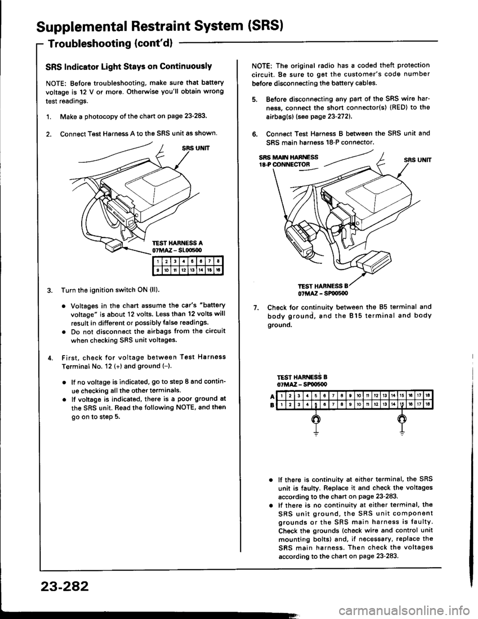
2. Connect Test Harness A to the SRS unit as shown.
Tu.n the ignition switch ON (lll.
. Voltages in the chart assume the car's "battery
voltage" is about 12 volts. Less than 12 volts will
result in different or possibly talse readings.
. Do not disconnect the airbags ftom the circuit
when checking SRS unit voltages.
First, check for voltage between Test Harnoss
Terminal No. 12 (+) and ground (-).
. lf no voltage is indicated, go to step I and contin-
ue checking all the other terminals.
o lf vottsge is indicated, there is a poor ground at
the SRS unit. Read the following NOTE, and then
go on to step 5.
I21I
tolll2t3tlrt
23-282
TEST HANNESS
NOTE: The original .adio has a coded theft protection
circuit. Be sure to get the customer's code number
before disconnecting the battery cables.
Before disconnecting any pan of the SRS wire har-
ness, connect the short connecto(s) {RED) to the
airbag(s) (see page 23-2721.
Connect Test Harness B between the SRS unit and
SRS main harn€ss 18-P connector.
7. Check for continuitv between the 85 terminal and
body ground, and the Bl5 terminal and body
ground.
TEST HARNESS B07MAZ - SPqrS{X)
lf there is continuity at either terminal, the SRS
unit is faulty. Replace it and check the voltages
according to the chan on page 23-283.
lf there is no continuity at either terminal, the
SRS unit ground, the SRS unit component
grounds or the SRS main harness is faulty
Check the grounds (check wire and control unit
mounting bolts) and, if necessary, replace th€
SRS main harness. Then check the voltages
according to the chart on page 23-283
Page 1397 of 1413
Supplemental Restraint System (SRSI
Troubleshooting {cont'dl
Modc H: Blown SRS No. 25 fur., ol opcn in the wire
NOTE: The original radio has a coded theft protection
circuit. Be sure to get the customer's code number
betore disconnecting the battery cables.
1. Ch€ck the SRS No. 25 (10 A) fuse in the under-dash
fuse/relay box. lf it's OK, go on to step 2.
lf it's blown, replace it with a now 10 A fuse, then
turn the ignition switch ON (ll):
. lf the fuse doesn't blow, 90 on to step 2.
. lf the fuse blows. troublsshoot as necessary to
find th6 short.
2. Disconnect the battery negative cable and then the
positive cable. Then connect the short connector(sl
(RED) to the airbag(s) (see page 23-272).
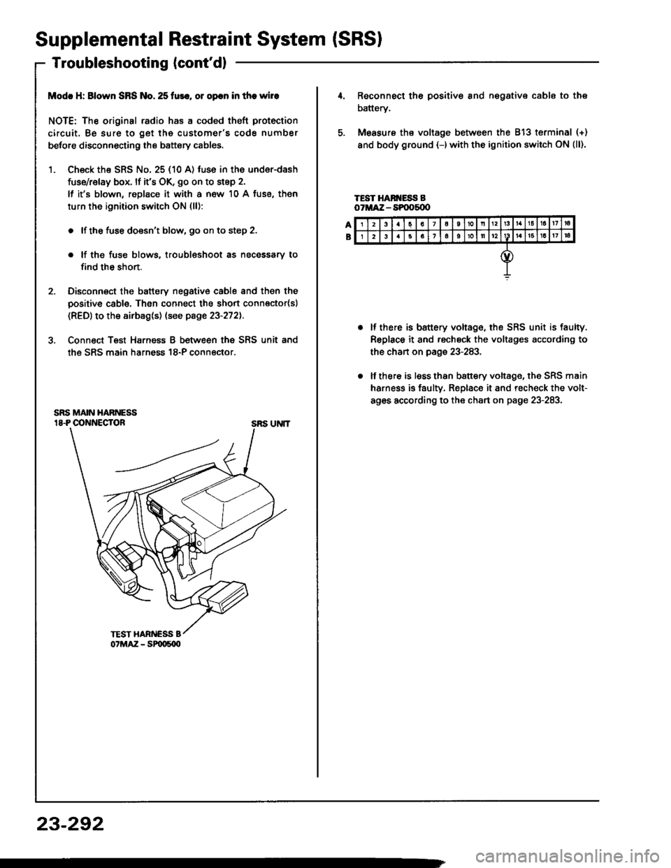
3. Conn€ct Teat Harnsss B between the SRS unit and
the SRS main harness 18-P connector.
SRS UNIT
23-292
23a7a10nl3161a17ra
26161oll12161a17|a
Reconnect th6 positiv€ 8nd negative cable to the
battery.
Measure ths voltage between the 813 terminal (+)
and body ground {-)with the ignition switch ON (ll).
TEST HAN ESS BoTMA:Z - SPOOs{X'
lf there is battery voltage, the SRS unit is faulty.
Replace it and rscheck the voltages according to
the chan on page 23-283.
lf there is lsss than b8ttery voltage, the SRS main
harness is faulty. Replace it and recheck the volt-
ag6s according to the chart on page 23-283.
Page 1398 of 1413
Modc l: Short 01 opcn in SRS indicrtor whc hrrnaas
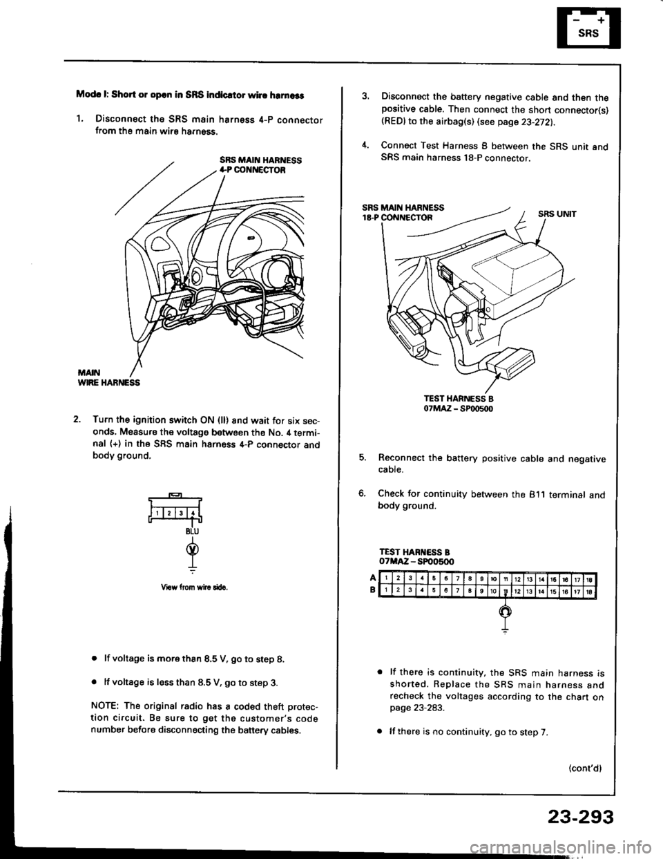
1. Disconnect tho SRS main harness 4-p connectorfrom the main wirs harn6ss.
WIRE HABNESS
2. Turn the ignition switch ON (ll) 8nd wait for six sec-onds. Measu.s the voltage between ths No. il termi-nal (+) in the SFS main harness 4-P connector andbody ground,
. lf voltage is more thsn 8.5 V, go to step 8.
. It voltage is less than 8.5 V, go to step 3.
NOTE: The original radio has a coded theft protec-
tion circuit. Be sure to get the customer's codenumber before disconnecting the banery cables.
*-
F4
BLU
d.L
Vrow llom wi|! rftro.
Disconnect the battery negative cable and then thepositive cable. Then connect the sho.t connector(s)(REDlto the airbag(s) (see page 23-272).
Connect Test Harness B between the SRS unit andSRS main harness 18-P connector.
5. Reconnect the battery positive cable and negativecaote.
6, Check for continuity between the 811 terminalbody ground.
lf there is continuity, the SRS main harness isshorted. Replace the SBS main narness anorecheck the voltages according to the chart onpage 23-283.
lf there is no continuity, go to step 7.
(cont'dl
23-293
Page 1399 of 1413
Supplemental
Troubleshooting(cont'dl
RestraintSystem (SRSI
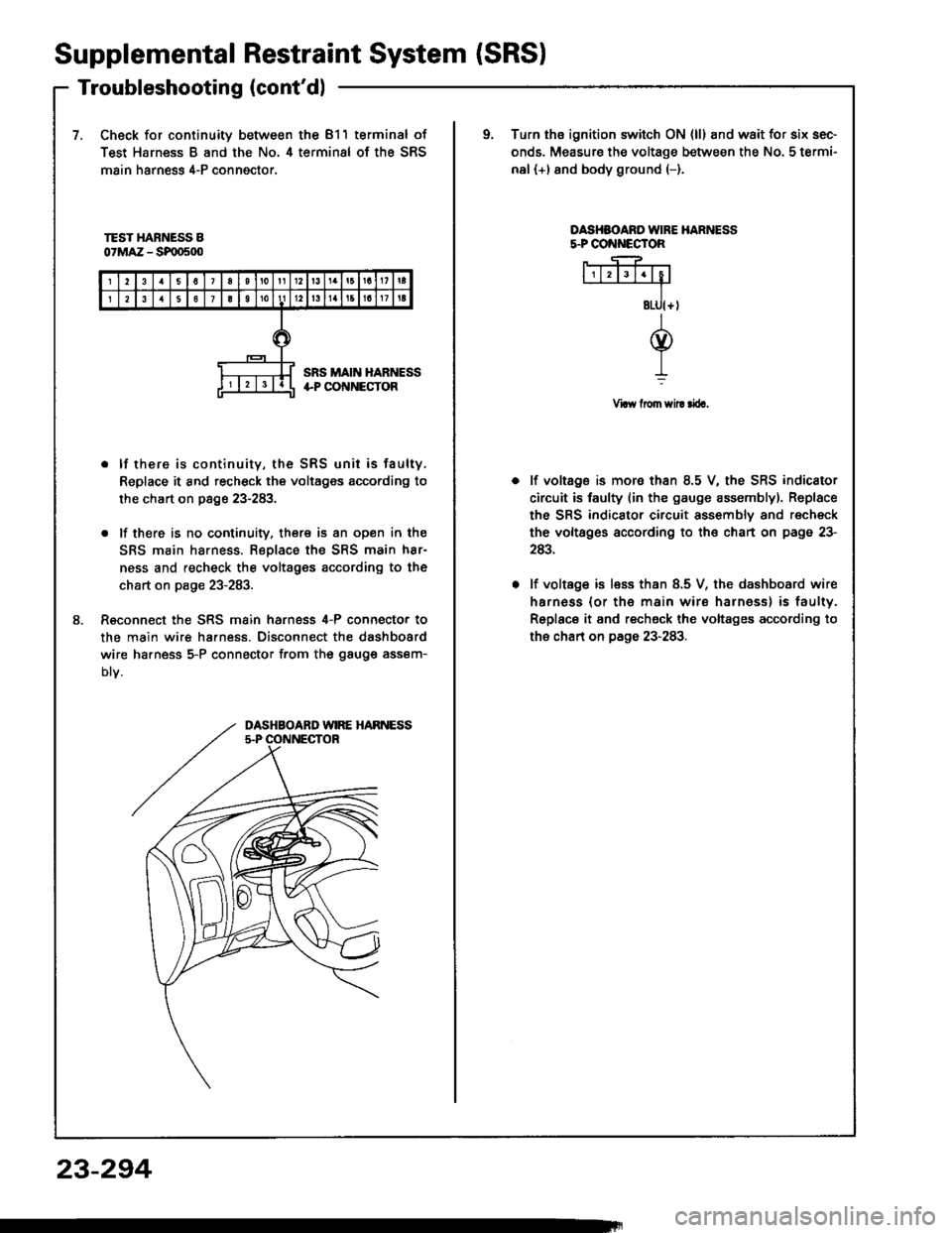
7.Check for continuity between the 811 terminal of
Test Harness B and the No. 4 terminal of the SRS
main harness 4-P conngctor,
oTurn ths ignition switch ON {ll} and wait for six sec-
onds. Measure the voltage between the No. 5 termi-
nal (+) and body ground (-).
TEST HARNESS B07MAZ - SF|D500
OASHSOARO IVIRE HARNESSs.PCO ECTOR
Vraw from sil! rira,
8.
. lf there is continuity, the SRS unit is faulty,
Replace it and recheck the voltages according to
the chart on page 23-283.
. lf there is no cootinuity. there is an open in the
SRS main harness. Replace the SRS main h8r-
ness and recheck the voltages according to the
chart on page 23-283.
Reconnect the SRS main harness 4-P connecto. to
the main wire ha.ness. Disconnect the dashboard
wire ha.ness 5-P connector from the gauge assem-
Dtv.
lf voltage is mora than 8.5 V, the SRS indicator
circuit is faulty (in the gauge assemblyl. Replace
the SRS indicator circuit assembly and recheck
the voltsges according to the chart on page 23-
243.
lf voltage is less than 8.5 V, the dashboard wire
harness (or th€ main wire harness) is faulty.
Replace it and recheck the voltages according to
the chart on page 23-283.
DASHBOARD WIRE HARNESS5.P OONNECTOR
23-294
Page 1404 of 1413
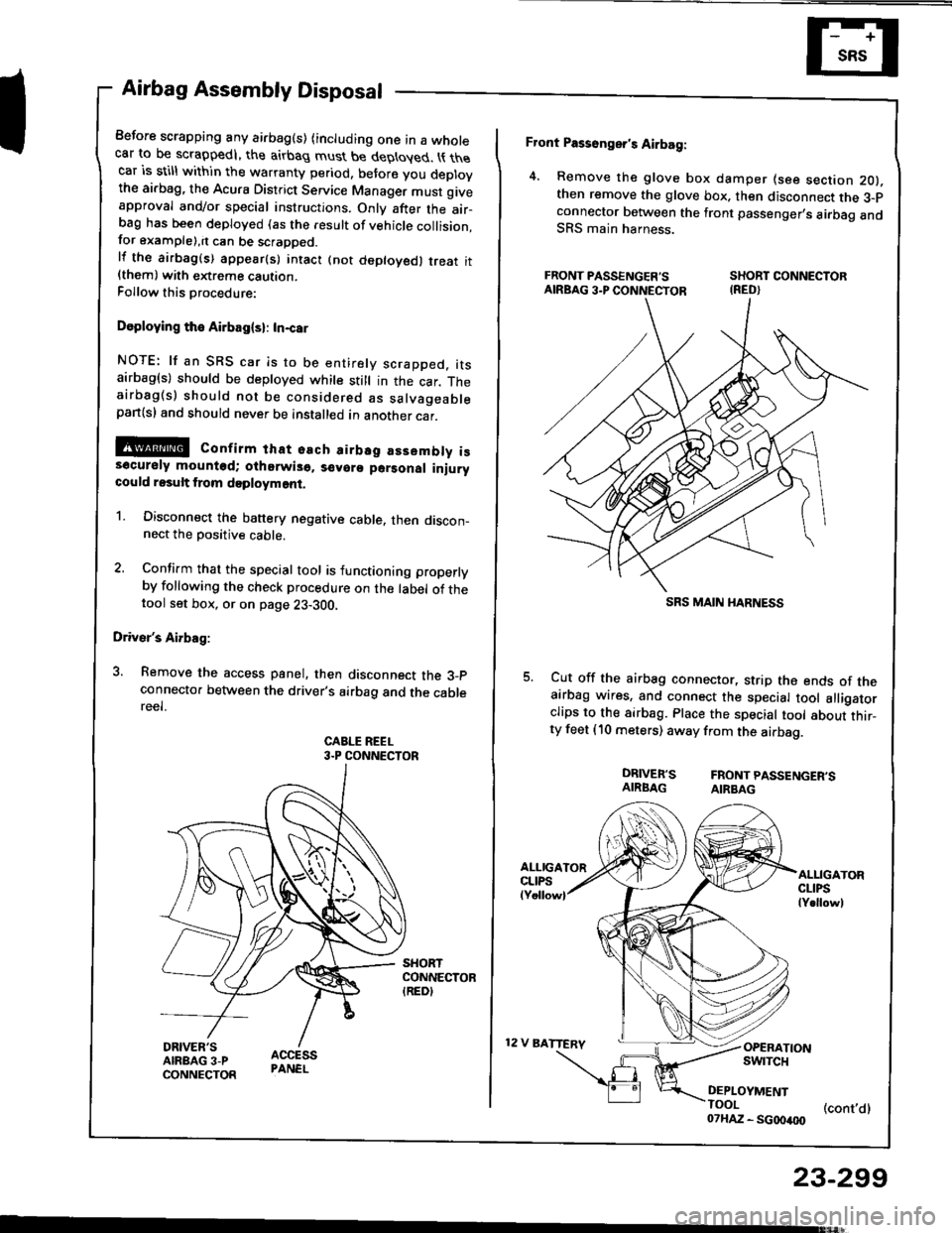
Airbag Assembly Disposal
Before scrapping any airbag(s) (including one in a wholecar to be scrappedl, the airbag must be deployed. t{ thecar is still within the warranty period, before you deplovthe ai.bag, the Acura District Service Manager must giveapproval and/or special instructions. Onlv after the air-ba9 has been deployed (as the result of vehicle collision,for example),it can be scrapped.lf the airbag(s) appear(s) intact (not deptoyed, treat it{them) with extreme caution.Follow this Drocedure:
Doploying the Airbag(sl: In-car
NOTE: lf an SRS car is to be entirely scrapped. itsairbag(s) should be deployed while still in the car. Theairbag(s) should not be considered as salvageablepan(sl and should never be installed in another car.
@ confirm that osch airbsg assembly iss6cursly mounted; oihorwis6. s€voro parsonal iniurycould result from doployment.
1. Disconnect the banery negative cable. then discon_nect the Dositive cable.
2. Confirm that the special tool is functioning properlyby following the check procedure on the label of thetool set box, or on page 23-300,
Driver's Airbag:
3. Remove the access panel, then disconnect the 3_pconnecto. between the driver's airbag and the cablereel.
CABLE REEL3.P CONNECTOR
Front Passonger's Airbag:
4. Remove the glove box damper (see section 2O).then remove the glove box. then disconnect the 3-pconnector botween the front passenger,s airbag andSRS main harness.
FRONT PASSENGER'S SHORT CONNECTORAIRBAG3.PCONNECTOR IRED}
Cut off the airbag connector, strip the ends of theairbag wires, and connect the special tool alligatorclips to the sirbag. Place the special tool about thir_ty feet (10 meters) away from the airbag.
DRIVER'S FRONTPASSENGER'SAIRBAG AIRBAG
12 V BATTERV
ALLIGATORCLIPSlY.llowl
OPERATIONswrTcH
DEPLOYMENTTOOI (cont,dl07HAZ - SG00400
23-299
SRS MAIN I{ARNESS
Page 1412 of 1413
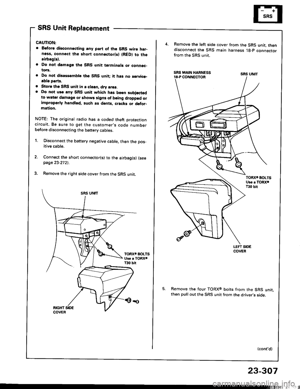
SRS Unit Replacement
CAUTION:
. 8€tor6 disconneciing any part of the SRS wire har-ness, connect the short connectorlsl (RED) to thosirbagl3).
o Do nol drmsgo thc SRS unit terminal! o. connoc-to.s.
. Do not disassemblo tho SRS unit; it ha3 no rervico-.blo parts.
. Storo tho SRS unit in a cleln, dry srea.. Do not us€ lny SRS unit which h.s been subisctodto wator damag€ or shows sign3 ol b€ing droppad orimproperly handl6d, such as dents. cracki or d6tor-mation.
NOTE: The original radio has a coded theft protectioncircuit. Be sure to get the customer,s code numberbefore disconnecting the baftery cables.
1. Disconnect the battery negative cable, then the pos_
itive cable.
Connect the short connector(s) to the airbag(s) (seepage 23-2721.
Remove the right side cover from the SRS unit.
4.Remove the left side cover from the SRS unit. thendisconnect the SRS main harness lg-p connectorfrom the SRS unit.
Remove the four TORXo bolts from the SRS unit,then pull out the SRS unit from the driver,s side.
(cont'd)
SRS UNIT
23-307