Page 1168 of 1413
Ground Distribution
Circuit ldentification
lHi0h berm)
'LK H[l[llsf#"ff'"Jfl1"'o"
Hom rol.y
lgdtion koy lrvitch
8r -;€[email protected]*'*.,F Cftxch svynch {M/T whh cruisc controllL Intorlocl conlrclunit I lArtoq_r- Ct rch htodock swhch lM/TlRa'r window wioar/washot lwitdl
t.BIK -{ |-{N�| 4.X -7 P!.rsong.r'! doot loct kcy cylind€r sYritchl- - l- P!s!6n06r's door bck 3witch
Windlhiald wio.r/w$h6r rwhch
Engin6 comprrtmonl wiro htrnds
Main wiro hftn.ss
Frcnt prsongor'! door wim hlmosg
llort.| lub - hamar! A
H6!t6r lub - harara$ B
BIK
@:
tlt .tr
tr
E
23-62
Page 1186 of 1413
![HONDA INTEGRA 1994 4.G Workshop Manual Starting
Startel
System
Overhaul
from clutch side.
-s@]
MOLYBDENUMDISULFIDE
CAUTION: Disconnecl th€ battery n€gative cable befole
lomoving the startet.
NOTE: The original radio has a coded theft p HONDA INTEGRA 1994 4.G Workshop Manual Starting
Startel
System
Overhaul
from clutch side.
-s@]
MOLYBDENUMDISULFIDE
CAUTION: Disconnecl th€ battery n€gative cable befole
lomoving the startet.
NOTE: The original radio has a coded theft p](/manual-img/13/6067/w960_6067-1185.png)
Starting
Startel
System
Overhaul
from clutch side.
-s@]
MOLYBDENUMDISULFIDE
CAUTION: Disconnecl th€ battery n€gative cable befole
lomoving the startet.
NOTE: The original radio has a coded theft protection
citcuit. Be sure to get the customer's code number before
- disconnecting the batterY.- removing the No.3 2 (7.5 A) fuse from the under-hood
fuse/relay box.- removing the tadio.
Atter service, reconnect power to the radio and turn at
on. When the word "CODE" is displayed, enter the cus-
tomer's 5-digit code to restore radio operation.
tr./.' BRUSH HOLDERTest, page 23-8'l
ERUSH
COVER
I
6
OVERRUNNING CLUTCH ASSEMBLYInspection, page 23_84
SOLENOIDPLUNGERInspection, page 23-85
BRUSH HOLOER
ARMATURE
STARTERSOLENOIDTest, page 23-78
PINION GEAR IDLER GEAR
Inspection, page 23-11
IDLER GEAR
I
@*
SOLENOID HOUSING
HARNESS BRACKET
STEEL BALL
install steel ball
lnspection and Test,page 23-82
ROLLER BEARINGSand CAGEPrevenl rollers trom being scattered and lost.
MOLYBDENUM DISULFIDE
_R1
MOLYADENUMDISULFIDE
23-80
ENO COVER
ARMATURE
GEAR HOUSING
Page 1242 of 1413
A/T GearPosition Indicator
A/T GeaPosition Switch Test
23-136
1.
2.
I I gear Fosluon Dwtrcn I esr -
Remove the console. then disconnect the 14-P con-
nector from the switch.
Check for continuitv between the terminals in each
position according to the table.
a Move the lever back and forth at each position
without touching the push button, and check tor
continuity within the range of free play.
a lf there is no continuity within the.ange of free
play, adjust the installing position ol the switch
as described on the next page.
A/T Goar Position Swhch (Without crulso contloll
A/T Goar Position Switch (With cruiss controll
tgrminal90e
14-P CONI{ECTOR
Back-up Noutrrl
Ught Swhch Polition Swhch
Back-up t{outral
Llght Swltch Potidon Swltch
Terminal
P*ii-_\BFNMDK
tro-
ao---o
Eo---o
Eo-
No--.oo-
tro--oo---o
tro---oo---o
Terminal
P*,i-
_\6NMDJK
tro---o
ao---.o
Eo---o
E--o
EG_o-
Eo-o---o
Eo---oo---o
Page 1261 of 1413
Gircuit Diagram (Canadal
BATTERY
G"*
UNOER_HOOD FUSEiRETAY 8OX
coMBrNAtor{ rcHrswnc
-il w
| '.=r" I
ll'L I I
I I *o\." l-'li' ;- ;j
I LI
"- r.r-,9 "orr
I
d "
L
RED/BLU REO/}VHT RED,ll
I UNDEN-DASH II FUSEiIEI,AY 8OX I
tl
L-J
t'GRN
/d\BATtG2\9-l
rGNrTrot{swITcH
No.2lfl0A)\I
No.l9|l04]Jm.tr (
t10A) ttt
I
No.l6{7.54}
tl
i,"#
llrrff li'rrt,
RED/GRtIIBLU REOr'TVHTINED/B
V
WHTTYEL
. DASH LGHTS BRIGHTNESSCOI{TROLLER. DASH I-IGHTS. PARKING I-GHIS. TAII,LIGHTS. UCENSE N"AT€ LIGI{TS
I a-rneonru jllA/Vr l"o I f# wxrintoRED/GRI{ +\{H I
DAYTIME RUNNINGUGI{TS RESISTOR
IRED/GRN
Hr I r-01651,1/) | l55W)HIt85W)LOt55Wl
HIGH BEAMINOICATORUGHTfl.4W
I
RIGHTHEADLIGHTPARKIIIGBRAKEsw{TcH
23-155
Page 1277 of 1413

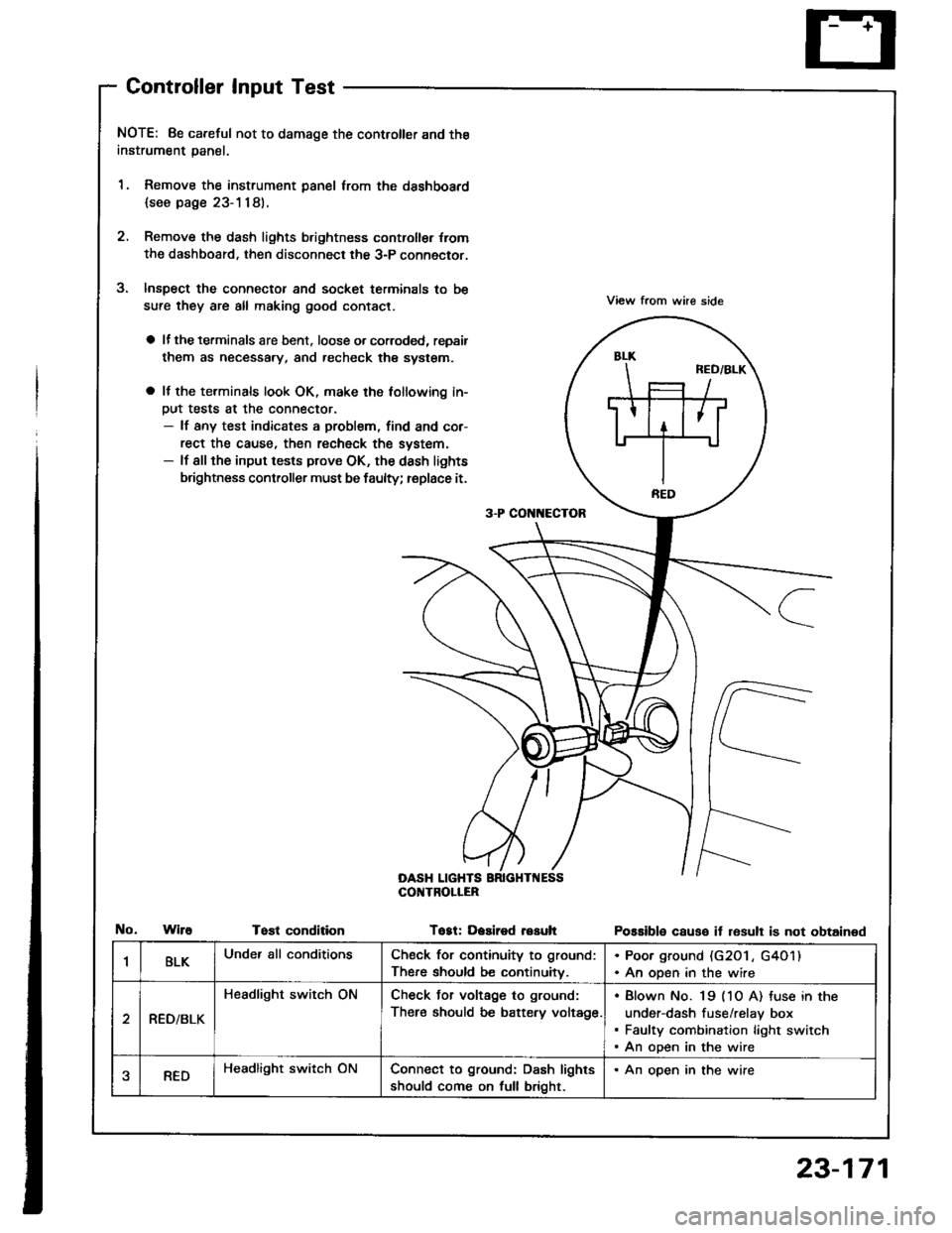
Controller Input Test
NOTE: 8e careful not to damage the controller and the
instrument panal.
1. Remove the instrument panel lrom the dsshboard
{see page 23-1181.
2. Remove the dash lights b.ightness controller {rom
the dashboard. then disconnect the 3-P connector.
Inspect the connector and socket terminals to be
sure they are all making good contact.
a lf the terminals are bent. loose o. corroded, repsir
them as necessary, and recheck the system.
a It the terminals look OK, make the tollowing in-
Dut tests at the connector.- lf any test indicates a problem, find and cor-
rect the cause, then recheck the system.- lf all the input tests prove OK, the dash lights
brightness controller must be faulty; replace it.
View from whe side
Possible causo it resull is not obtained
3-P CON[{ECTOR
OASH LIGHTSCOI{TROLIER
WireTost conditionTogt: Dasired resuh
1BLKUnder all conditionsCheck for continuity to ground:
There should be continuitv.
. Poor ground (G20 l , G4O1). An open in the wire
RED/BLK
Headlight switch ONCheck Jor voltage to ground:
There should be battery voltage.
Blown No. 19 (1O A) tuse in the
under-dash fuse/relay box
Faulty combination light switch
An open in the wire
aREDHeadlight switch ONConnect to ground: Dash lights
should come on full bright.
. An open in the wire
23-171
Page 1291 of 1413
UNDEN-HOOD FUSE/RELAY 8OX
N0.41 1100A) No.40 (50A)
Gircuit Diagram
COMBINATIONLIGHTSWTCHA.---of-RED/GRN
IGNITION SWITCH
/6i\WHT/BTK +WHT+ +- BIK/YET
\jv
UNDER-DASH FUSE/RELAY 8OX
FUSE HOTJER
GRN/BtU
TURN SIGiIALswtTcH
I
|l
+DASH TIGHTSBRIGHTNESSCONTROLLER
SIOE MAFKER LIGHTFLASHER CIRCUITlln tho intogruted controlunitl
RIGHT TURN SIGNAT TIGHTS
INOICATOR I FRONT I REARL|GHT I t32CD I t32CPl(1.4W1
23-185
Page 1312 of 1413
Rear Window Defogger
Component Location Index
CAUTION:
a All SRS olectrical wi ng ham€$6s are covoled with
y€llow insulation.
B6foro disconnocting any part of ths SRS wire har-
ness. connoct tho short connector(s).
Roplacs the ontire affectod SRS harness assombly if
it has an open circuit or damagcd wiring.
REAB WINDOWDEFOGGER RELAYTest, page 23-68
REAR WINDOWDEFOGGER SWITCHRemoval, page 23-209Test, page 23-2Og
REAR WINDOW DEFOGGERTest, page 23-210
UI{DER.DASH FUSE/RELAY BOX
REAR WINDOW DEFOGGER TIMER CIRCUIT
{ln the integrated control unil)fnput Test, page 23-147
SRS MAII{ HAR'{ESS
The rear window defogger is controlled by the integrated control unit, Pushing the defogger switch in the instrument
panel it sends a signal to the defogger time. in the integrated control unit, and the detogger stays on tor 25 minutes
or until the ignition switch is turned off. The indicator light in the switch comes on when the deJogger works.
23-206