Page 155 of 1413
Pistons
Inspection
1. Check the oiston for distortion or cracks.3, Calculate the difference betw€on cvlinder bore
diameter on (see page 7-13) and piston diametsr.
Pbton-io"Cy'indor Clea18nco:
Stsndard (Nrwl: 0.010 - 0.0/O mm
{o.ofira - 0.0016 in}
S.rvic. Limit: 0.05 mm {0.002 in)
NOTE: lf the cylinder is bored, an oversized piston
must be used,
2. Moasur€ the piston diameter at a point l5 mm
(0.6 in) from the bottom of the skin.
Pbion Diamat6r:
Standard lNowl: 80.S - 80.99 mm(3.188 - 3.189 inl
Sorvica Limit 80.97 mm (3.188 in)
lf the clearance is near or €xc€eds the service limit,
inspect the piston and cylinder block for excessive
wear.
Ov.rsizc Pilton Diamcter:
O.25t 81,23 - 81.21|rnm {3.1980 - 3.198'l in)
rKI
7-1
Page 156 of 1413

Piston
lnstallation
'1.
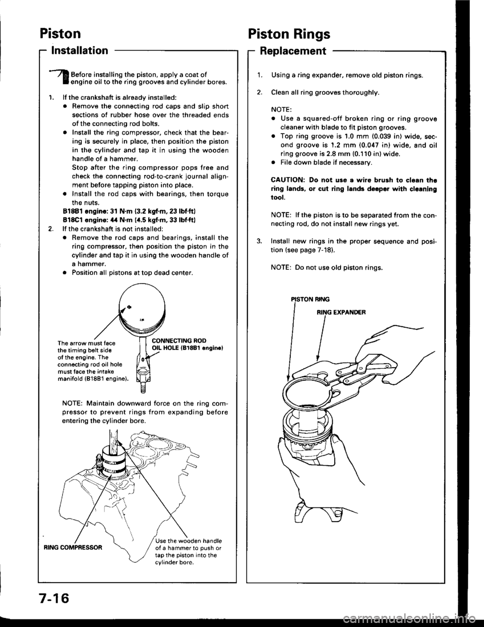
Before installing the piston, apply a coat ofengine oil to the ring grooves and cylinder bores.
lf the crankshaft is already installed:
. Remove the connecting rod caps and slip short
sections of rubber hose ove. the threaded ends
of the connecting rod bolts.
a Install the ring compressor, check that the bear'
ing is securely in place, then position the piston
in the cylinder and tap it in using the wooden
handle of a hammer.
Stop after the ring compressor pops free and
check the connecting rod-to-crank journal align-
ment before tapping piston into place.
. Install the rod caps with bearings, then torque
the nuts,
81881 ongino: 31 N.m {3.2 kgf.m, 23 lbf.ftl
818C1 cngino: 44 N'm 1,t.5 kgf.m, 33 lbf.ftl
lf the crankshaft is not installed:
o Remove the rod caps and bearings. install the
ring compressor, then position the piston in the
cylinder and tap it in using the wooden handle of
a nammer.
. Position all Distons at toD dead center.
CONNECTING RODOIL HOI-E (Br8Bl onginelThe arrow must facethe timing belt sideof the engine. Theconnecting rod oil holemust lace the intak€manifold {81881 €ngine).
NOTE: Maintain downward force on the ring com-
pressor to prevent rings from expanding before
entering the cylinder bore,
BING COMPRESSORUse the wooden handleof a hammer to push ortap the piston into thecylinder bore.
Piston Rings
Replacement
1.Using a ring expander, remove old piston rings.
Clean all ring g.ooves thoroughly.
NOTE:
. Use a squared-oJf broken ring or ring groove
cleaner with blade to fit piston grooves.
. Top ring groove is 1.0 mm (0.039 in) wide, sec-
ond groove is 1.2 mm (0.047 in) wide. and oil
ring groove is 2.8 mm (0.110 in) wide.. File down blade if necessary.
CAUTION: Do not use a wire brush to cloan thr
ring lands, or cut ring lands dsopo. with cl€aning
tool.
NOTE: lf the piston is to be separated from the con-
necting rod, do not install new rings yet.
Install new rings in the prope. sequence and posi-
tion (see page 7-18).
NOTE: Do not use old piston rings.
Page 157 of 1413

I
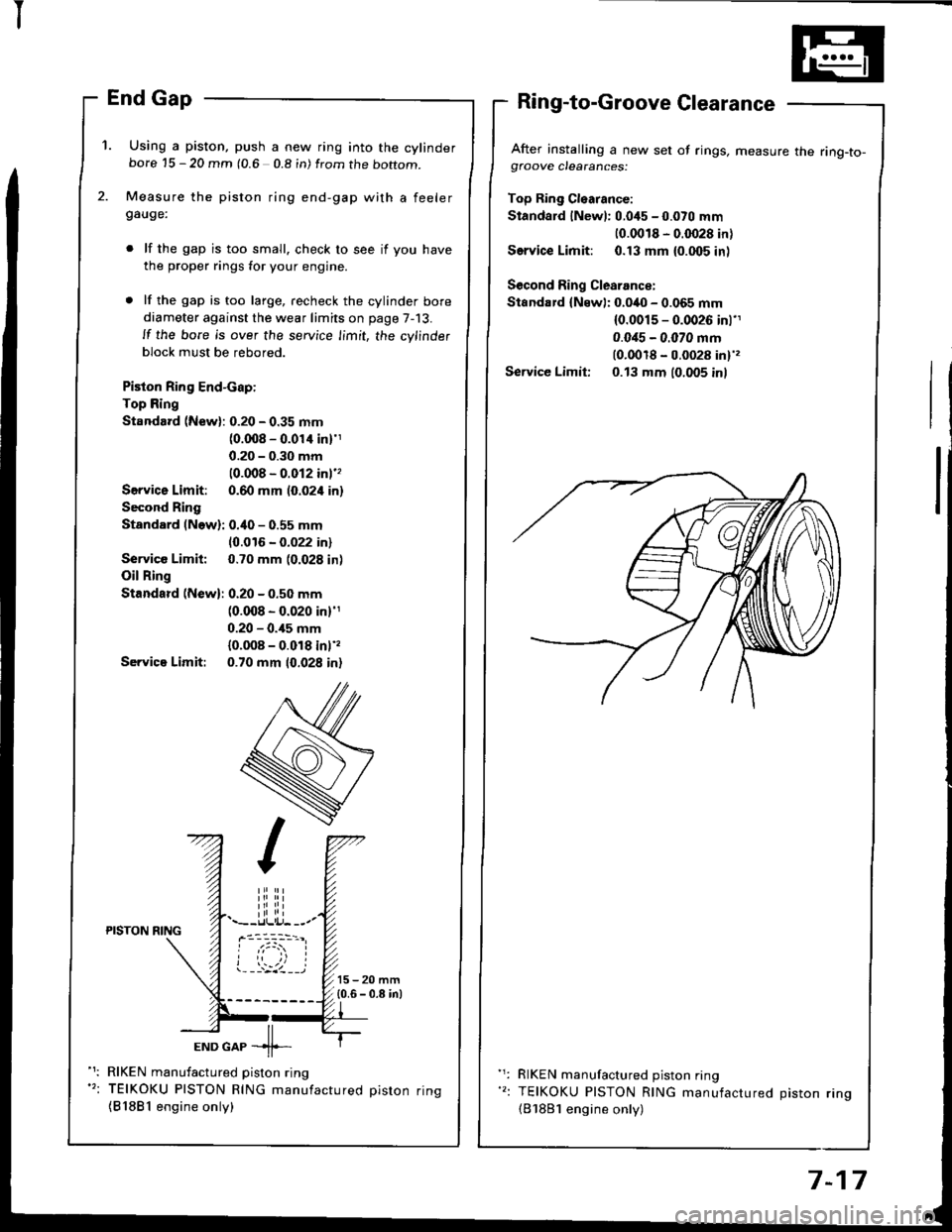
'1. Using a piston, push a new ring into the cylinderbore 15 - 20 mm (0.6 0.8 in) from the boftom.
Measure the piston ring end-gap with a feelergauge:
lf the gap is too small. check to see if you have
the proper rings for your engine.
lf the gap is too large, recheck the cylinder bore
diameter against the wear limits on page 7-13.
ll the bore is over the service limit, the cylinder
block must be rebored.
Piston Ring End-cap:
Top Ring
Standard (New): 0.20 - 0.35 mm(0.008 - 0.01'l inl'1
0.20 - 0.30 mm
10.008 - 0.012 inl''
Servica Limit: 0.60 mm (0.024 in)
Second Ring
Standard (Now): 0.40 - 0.55 mm
10.016 - 0.022 in)
Service Limit: 0.70 mm (0.028 in)
Oil Ring
Standard (New): 0.20 - 0.50 mm(0.008 - 0.020 in)'1
0.20 - 0.,15 mm
{0.008 - 0.018 inl',
Servica Limit: 0.70 mm 10.028 in)
After installing a new set of rings, measure the ring-to-gfoove clearances:
Top Ring Cl€arance:
Standard lNewl: 0.045 - 0.070 mm
10.0018 - 0.0028 in)
Service Limit: 0.13 mm {0.005 inl
Second Ring Clearance:
Standard {Newl: 0.040 - 0.065 mm(0.0015 - 0.0026 inl'1
0.0i15 - 0.070 mm(0.0018 - 0.0028 in)',
Service Limit: 0.13 mm (0.005 inl
iliiii.--r.llli.j- --.-PISTON NING
ioi
---'z llEND GAP -11--
RIKEN manufactured piston ring
TEIKOKU PISTON RING manufactured oiston rinq
{81881 engine only)
RIKEN manufactured piston ring
TEIKOKU PISTON RING manufactured Diston rino(B'1881 engine only)
7-17
Page 161 of 1413
3. Measuro the piston pin-to-piston clearance.
NOTE: Check the Diston for distonion or cracks.
It the piston pin clearance is greater than 0.022 mm(0,0009 in), remeasure using an ovorsize piston pin.
Pbton Pin-to-PLton Cloeranco:
StlndErd (Ncwl: 0.010 - 0.022 mm(0.(xto4 - o.(Xxlg inl
4. Check the difference betwsen piston pin diameter
and connecting rod small end diam€ter.
Pbton Pin-to4onnocting Rod Inlcdaranca:
Strndlrd {Ncw}:
Bl8Bl ongino: 0.013 - 0.G12 mm(0.fiX15 - 0.0013 inl
Bl8Cl cngin.: 0.017 - 0.036 mm
IO.ON1 - O.|,o11 int
Connecting Rods
End Play
NOTE: End play should bs insp€cted before removing
the crankshaft.
Connrcting Rod End Pl.y:
Stlndrrd (Nrwl: 0.15 - o.3o mm(0.(xt6 - 0.012 inl
Scrvict Limit o./to mm (0.016 inl
lf out-of-tolerance, install a new connscting rod.
lf still out-of-to16rance, replace the crankshaft
pages 7-10 and 7-22)
a
a
7-21
Page 163 of 1413

Rotate the crankshaft clockwise, put journals into
connecting rods No. 1 and No. 4, and install the rod
caps and nuts finge.-tight.
NOTE: lnstall caps so the bearing recess is on the
samg side as the .ecess in the rod.
Check rod bearing clsarance with plastigage (see
page 7-9), then tighten the capnuts in 2 steps.
l3t 3t.p: 20 N.m (2.0 kgf.m, rl btfil
2nd 3tep:
81881 cnginc: 31 N.m (3.2 kgf.m, 23 lbf.ft)
818C1 .ngin!: ,14 N.m (4.5 kgt.m,33 lbf.ft)
NOTE: Reference numbers on connecting rod are
for big-end bore tolorance and do NOT indicate the
positioo of piston in the engine.
Install the main bearings/caps and cap b.idge(818C1 engine onlyl.
NOTE: Coat the bolt threads with oil.
CAP BRIDGElBlSCl .noin. onlyl
EEARIlTG
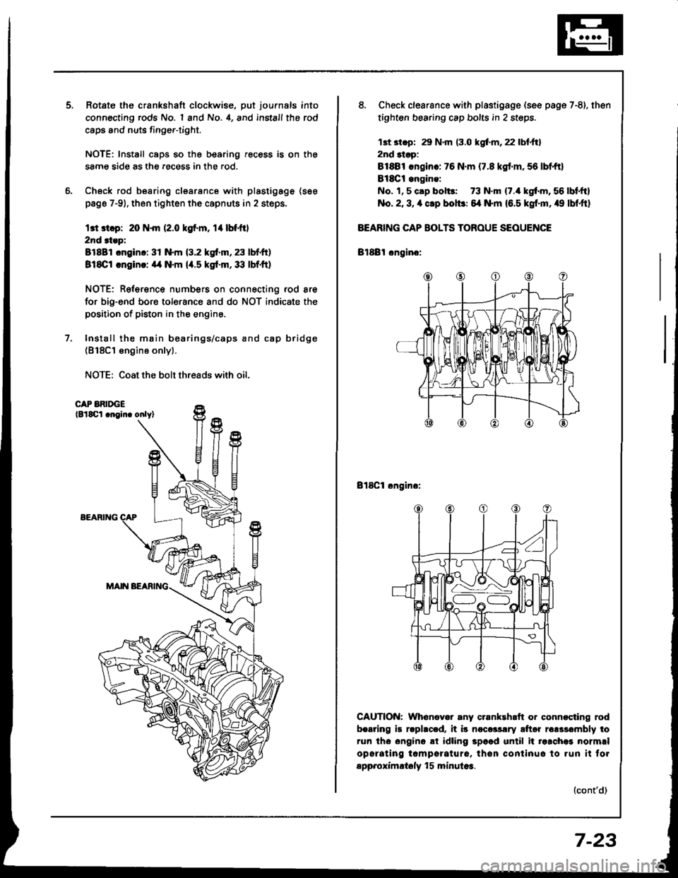
8. Check clearsnce with plastigsge (see page 7-8). then
tighten bearing cap bolts in 2 steps.
13t st.p: 29 N.m (3.0 kgf.m, 22 lbt.ftl
2nd 3tsp:
81881 .ngin.: 76 N.m (7.8 kgt.m,56 lbf,ft)
Bl8Ct engine:
No. 1, 5 cap bol$: 73 N.m (7./r kgf'm, 56 lbf,ftl
No. 2, 3, a clp bolbr 6{ N.m (6.5 kgf'm, /r9 lbf,ftl
BEARING CAP BOLTS TOROUE SEOUENCE
Bl88l cngino:
Bl8Cl ongino:
CAUTION: Whenever any crsnkehaft or connocting rod
b.aring is rlphccd. it i5 ncccrsrry aftor rclssombly to
run tho ongino ai idling 3p6ad until it re.chei normrl
opcrating tcmporature, thon continuo to run it fol
spp.oximltoly f 5 minula3.
(cont'd)
7-23
Page 169 of 1413

lllustrated Index
DRATT PIUG \44 .m (4.5 tgf.m, 33 lbf'ftl \Do not ovgr tightgn. \-@5
OIL PAI{
6 r l.O mtn121{.m 11.2 kol.m,I lbl.ttl
CAUTIOIiI: Do not ovortighten the drain plug.
81881 sngine:
WASHERReplace.
O|L BNEATHERTAIIK
eq
nU2o@
\
u
I
#-'
GASKETR6placs,
NOTE;
o Use new O-rings when reassembling.
a Apply oil to O-rings betore installation,
. Use liquid gasket, Part No. O8718-OOO1.
a Clean the oil pan gasket mating surtaces before in-
stalling it.
6 x'l.o mm12 N.m {1.2 kgt.m, 9 lbt.tt)
6 x 1.0 mm'11 N.m 11 .1 kgt'm,8lbt.ftl
6 x 1.O mmll N.m {1.1 kgf'm,
OIL SCREEN
A
,F
HEAD OILCONTROL ORIFICECIean.
I tbt.ftl
OIL FILRepl.cemont, p6gs 8-6
ENGINE OIL PRESSUREswlTcH18 .m 11.8 kgl.m, 13lbl.ftl'l/8 in. BSP lgritish StandardPioo Taporl 28 Threads/inch.Use propgr laquid 56alant.
GASKETReplace.
BAFFLE PTATE
I x 1.25 mm24 N.m 12.4 kgf..n,17 rbr.ftl
6 x 1.O mm11 N-m (1.1 kgt.m,8lbf.ft)OIL PUMPOverhaul, page 8-9lnspection page, 8-1OApply liquid gasket toblock mating surlace.(cont'dl
8-3
Page 170 of 1413

lllustrated Index
(cont'dl
CAUTION: Do not overtighten rhe dlain ptug.
818C1 engine:
NOTE:
a Use new O-rings when reassembling.
a Apply oil to O rings before installation.. Use liquid gasket. Part No. 08718-OOO1.
a Clean the oil pan gasket mating surfaces before in-
stalling it.
OIL PAN
Replace.
6 x 1.0 mm12 N.m 11.2 kgl.m, 9 lbf.ftl
6 x 1.0 mm11 N.m 11.1 kgt.m,S lbf.fil
OIL JET BOLT16 N.m {'1.6 kgf.m, '13 lbf.ft}
OIL JETBe careful not to damage.Inspection, page 8-8
O-RINGReplace.
EAFFLE PLATE
6xl.0mm11 N.m (1.1 kgt.m, I lbt.ft)
OIL SCREEN
GASKETReplace.
6 r '1.0 mml1 N.m (1.18 rb-trlK9-m,
O-RINGReplace.
HEAD OIL CONTROLORIFICEClean.
8 x 1.25 mm24 N.m (2.4 kg-m, 17 lb-ft)ENGINE OIL PR€SSUREswtTcH1A N.m {1.8 kgf.m, 13 lbf.ft)1/8 in. BSP {British StandardPipe Taperl 28 threads/inch.Use proper liquid gasket.
OIL PUMPOverhaul, page 8-9Removal/lnspection/lnstallation, page 8-10Apply liquid gasket to matingsurface ot the engine block.
Il
,--)e6V
ENGINE OIL COOLER
ENGINE OIL FILTERReplacement, page 8-6
OIL COOLERCE TER BOLT74 N.m (7,5 kgf.m, 54 lbf.ft)
DRAIN PLUG44 N.m (4.5 kgf.m, 33 lbt.ftlDo not overtighten.
8-4
Page 174 of 1413

Oil Pressure
Testing
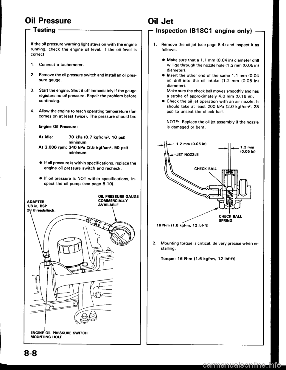
lf the oil pressure warning light stays on with the enginerunning, check the engine oil level. lf the oil level is
correct:
1. Connect a tachometer.
2. Remove the oil pressure switch and install an oil pres-
sure gauge.
3. Stan the engine. Shut it off immediately if the gauge
registers no oil pressure. Repair the problem before
continuing.
4. Allow the engine to reach operating temperatu,e {fancomes on at least twice). The Dressure should be:
Engine Oil Pressure:
At ldle: 70 kPa (0.7 kgf/cmr, 10 psi)
minimum
At 3,OOO lpm: 340 kPa {3.5 kgf/cmz, 50 psi}
minimum
a lJ oil pressure is within speciJications, replace the
engine oil pressure switch and recheck.
a lf oil pressure is NOT within specifications, in-
spect the oil pump (see page 8-1O).
1.2 mm 10.05 in)
'16 N.m (1.6 kgt.m, l2lbt.ftl
Oil Jet
Inspection (B18C1 engine only|
Remove the oil jet (see page 8-4) and inspect it as
follows.
a Make sure that a I .l mm (O.04 in) diameter drill
will go through the nozzle hole {1 .2 mm {O.OS in)
diameterl.
a Insert the other end of the same 1.1 mm (O.O4
in) drill into the oil intake {1.2 rnm {0.05 in}
diameter).
Make sure the check ball moves smoothlv and has
a stroke of approximately 4.0 mm {O. 16 in).a Check the oil jet operation with an air nozzle. lt
should take at least 2OO kPa (2.O kgf/cmr,28
Dsi) 10 unseat the check ball.
NOTE: Replace the oiljet assembly if the nozzle
is damaged or bent.
2. Mounting torque is critical. Be very precise when in-
stalling.
Torque: 16 N.m (1.6 kgt.m, 12lbf.ftl
OIL PRESSURE GAUGECOMMERCIALLYAVAILABI.E
8-8