Page 139 of 1413
11.
12.
13.
Cylinder Head
Installation lcont'd)
lnstallthe timing belt lsee page 6-51).
Adjust the valve clearance (see page 6-44).
Install the rubber seal in the groove of the cylinder
head cover. Seat the seal in the recesses for the
camshaft first, then work it into the groove around
the outside edges.
NOTE:
. Before installing the rubber seal. thoroughly
clean the seal and the groove.
. When installing, make sure the seal is seatedsecurely in the corners of the recesses with nogap.
COVER
6-78
14. Apply liquid gasket to the rubbe. seal at the eightcorne.s of the recesses.
NOTE:
. Use liquid gasket, Part No. 08718 - 0001.. Check that the mating surfaces are clean and dry
before applying liquid gasket.
a Do not install the parts if 20 minutes or more
have elapsed since applying liquid gasket.
Instead,.eapply liquid gasket after removing oldresidue.
r After assembly, wait at least 20 minutes beforefilling the engine with oil.
Apply liquid gasket tothe shaded areas.
Page 140 of 1413
When installing the cylinder head cover. hold the
rubber seal in the groove by placing your fingers on
the camshaft contacting surfaces (top of the semi-
circles).
Once the cylinder head cover is on the cylinder
head, slide the cover slightly back and forth to seat
the rubber seal.
NOTE:
Before installing the cylinder head cover, clean
the cylinder head contacting surfaces using a
shop towel.
Do not touch the pans where liquid gasket was
applied.
6x1.0mm9,8 N.m 11.0 kgt'm,7.2 tffirl
Tighten the nuts in 2 or 3 steps. In the final step'
tighten all nuts, in sequence, to 9.8 N'm (1.0 kgf'm,
7.2 tbf.ft).
After installing, check that all tubes, hoses and con-
nectors are installed correctly.
17.
6-79
Page 142 of 1413
Special Tools
I
Raf. No. I Tool NumbcrDcacriptionOty I Pago Rotcrenc.
o
@
@
@
o
@
o
@
o
@
o
07GAF - PF60300
07HAF - P120102
OTLAD _ PR4O1OA
07LAF - PR30100
07LAB - PV00100 or
07924 - PD20003 or
01924 - PD20002
07948 - S800101
07749 - 0010000
07973 - PE00310
07973 - PE00320
07973 - 5570500
07973 - 6570600
Piston Pin Ease lnsert
Piston Base Head
Seal Oriver
Pilot Collar
Ring Gear Holder
Driver Attachment
Driver
Piston Pin Driver Shaft
Piston Pin Driver Head
Piston Base
Piston Base Spring
1
I
1'I
1
1
1
1
1
1
1
7-14,19,20
1-18, 19,20
7-19,20
7-1
7 -25, 26
7-19,20
1-19.20
1-18, 19, 20
1-18
Eg
o@,a\
o@
@@
0
7-2
Page 158 of 1413
Piston Rings
Alignment
1.Installthe rings as shown.
ldentify top and second rings by the chamfer on the
edge. Make sure they are in their proper grooves on
the prston.
NOTE: The manufacturing marks must be facing
upwaro.
TOP BING
OIL RINGSPACER
3. Position the ring end gaps as shown:
DO NOT position any ring gapsEcoNo R|NG GAp -.- :': :.-"' : - ' '----'-- { _- - - at prston thrust surfaces.
App.ox. 90"
OIL RING
ls" GAP
TOP BING GAPSPACER GAP
Rotate the rings
do not bind.
DO NOT position any ring gapin line with the piston pin hole.
SECOND RING
in their grooves to make sure they
MARK
OIL RING GAP
Piston Pins
Removal
1. Assemble the Piston Pin Tools as shown.
PISTO]T PIN BASE INSEN|T--r otGAF- PH6{t1,0
PISTON BASE HEAD
--l
PISTON BASE SP '{G07973 - 65r06{X'
7-18,
Page 159 of 1413

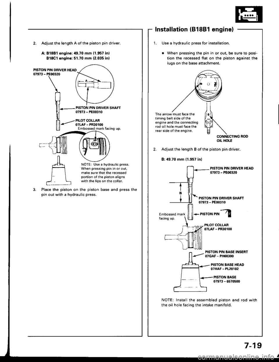
Installation (B18Bl engine)
2. Adjust the length A of the piston pin driver.
A:81881 engine:49.70 mm {1.957 inl
Bl8Cl €ngin€:51.70 mm {2.035 inl
PISTON PIN DRIVER HEAD07973 - PE00320
PISTON PIN DRIVER SHAFT07973 - PE00310
PILOI COLLAR07LAF - PR30100Embossed mark facing up.
NOTE: Use a hydraulic press.When pressing pin in or out,make sure that the recessedportion of the piston alignswith the lips on the collar.
Place the piston on the piston base and press the
pin out with a hydraulic press.
1. Use a hvdraulic oress for installation.
When pressing the pin in or out, be sure to posi-
tion the recessed flat on the piston against the
lugs on the base attachment.
The arrow must face thetiming belt side o{ theengine and the connectingrod oil hole must face therear side of the engine,
otl Hols
2. Adjust the length B of the piston pin driver.
B: 49.70 mm (1.957 inl
PISTON PIN DRIVER HEAD07973 - PEfl)320
PISTON PIN DR|VEN SHAFT079?3 - PE|X)310
Embossed mark
ffi*.r,"ror","l
PILOT COLLAN07LAF - PF301(x)
PISTON PIN BASE INSERT07GAF- PH603oO
PISTON BASE HEAD07HAF - PL20t02
PISTON BASE079?3 - 6570500
NOTE: lnstall the assembled piston and rod with
the oil hole facing the intake manifold.
7-19
Page 160 of 1413

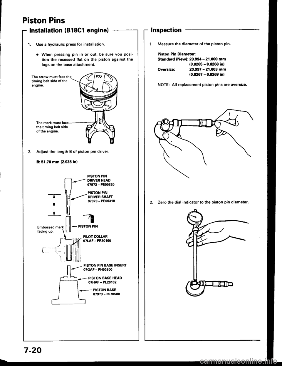
Piston Pins
Installation lB18C1 enginel
1. Use a hydraulic press for installation.
. When pressing pin in or out, be sure you posi-
tion the recessed flst on the piston against the
lugs on the base attachment,
Th€ arrow must tacetiming belt sid€ of rheengino.
Tho mork must tacethe timing belt sideot the engine.
PISTON PIN
fl--.l DRr
ER HEAD
I j 07e73 - PEm32o
ll t PlsroN PtN-T- \J ---..'' DRtvER sHAFr
; tl i- 07s73 - PEoo3lo
r ll-,H, -4
ilil r
Embossed m.rk ll ll-- PISTON PIN
facins up. l!-lJ
t PILOT COLLAR
I =)ffi o?LAF-PR3o1n'
r --t- 'llllrllilill
i_r_,llll,ltlllll
L-lt|lllltlll
Adjust the l€ngth B of piston pin driver.
Br 51.70 mm (2.035 inl
_- PrsroN PIN BASE INSERTO?GAF - PH6O3q)
PISTON BASE HEAD07HAF - P120102
PISTON BASE07973 - 65705U)
Inspection
Measure the diameter of the piston pin.
Pi3ton Pin Dirmltlr:
Standard lN.wl: 20.994 - 21.dlo mm(0.8265 - 0.8:168 inl
20.907 - 21.(xxt mm
(0.8267 - 0.&16S in)
Ovo.3ize:
NOTE: All replacement piston pins are oversize.
2. Zero the dial indicator to the piston oin diamater.
7-20
Page 169 of 1413

lllustrated Index
DRATT PIUG \44 .m (4.5 tgf.m, 33 lbf'ftl \Do not ovgr tightgn. \-@5
OIL PAI{
6 r l.O mtn121{.m 11.2 kol.m,I lbl.ttl
CAUTIOIiI: Do not ovortighten the drain plug.
81881 sngine:
WASHERReplace.
O|L BNEATHERTAIIK
eq
nU2o@
\
u
I
#-'
GASKETR6placs,
NOTE;
o Use new O-rings when reassembling.
a Apply oil to O-rings betore installation,
. Use liquid gasket, Part No. O8718-OOO1.
a Clean the oil pan gasket mating surtaces before in-
stalling it.
6 x'l.o mm12 N.m {1.2 kgt.m, 9 lbt.tt)
6 x 1.0 mm'11 N.m 11 .1 kgt'm,8lbt.ftl
6 x 1.O mmll N.m {1.1 kgf'm,
OIL SCREEN
A
,F
HEAD OILCONTROL ORIFICECIean.
I tbt.ftl
OIL FILRepl.cemont, p6gs 8-6
ENGINE OIL PRESSUREswlTcH18 .m 11.8 kgl.m, 13lbl.ftl'l/8 in. BSP lgritish StandardPioo Taporl 28 Threads/inch.Use propgr laquid 56alant.
GASKETReplace.
BAFFLE PTATE
I x 1.25 mm24 N.m 12.4 kgf..n,17 rbr.ftl
6 x 1.O mm11 N-m (1.1 kgt.m,8lbf.ft)OIL PUMPOverhaul, page 8-9lnspection page, 8-1OApply liquid gasket toblock mating surlace.(cont'dl
8-3
Page 170 of 1413

lllustrated Index
(cont'dl
CAUTION: Do not overtighten rhe dlain ptug.
818C1 engine:
NOTE:
a Use new O-rings when reassembling.
a Apply oil to O rings before installation.. Use liquid gasket. Part No. 08718-OOO1.
a Clean the oil pan gasket mating surfaces before in-
stalling it.
OIL PAN
Replace.
6 x 1.0 mm12 N.m 11.2 kgl.m, 9 lbf.ftl
6 x 1.0 mm11 N.m 11.1 kgt.m,S lbf.fil
OIL JET BOLT16 N.m {'1.6 kgf.m, '13 lbf.ft}
OIL JETBe careful not to damage.Inspection, page 8-8
O-RINGReplace.
EAFFLE PLATE
6xl.0mm11 N.m (1.1 kgt.m, I lbt.ft)
OIL SCREEN
GASKETReplace.
6 r '1.0 mml1 N.m (1.18 rb-trlK9-m,
O-RINGReplace.
HEAD OIL CONTROLORIFICEClean.
8 x 1.25 mm24 N.m (2.4 kg-m, 17 lb-ft)ENGINE OIL PR€SSUREswtTcH1A N.m {1.8 kgf.m, 13 lbf.ft)1/8 in. BSP {British StandardPipe Taperl 28 threads/inch.Use proper liquid gasket.
OIL PUMPOverhaul, page 8-9Removal/lnspection/lnstallation, page 8-10Apply liquid gasket to matingsurface ot the engine block.
Il
,--)e6V
ENGINE OIL COOLER
ENGINE OIL FILTERReplacement, page 8-6
OIL COOLERCE TER BOLT74 N.m (7,5 kgf.m, 54 lbf.ft)
DRAIN PLUG44 N.m (4.5 kgf.m, 33 lbt.ftlDo not overtighten.
8-4