1994 HONDA INTEGRA valve cover
[x] Cancel search: valve coverPage 1071 of 1413
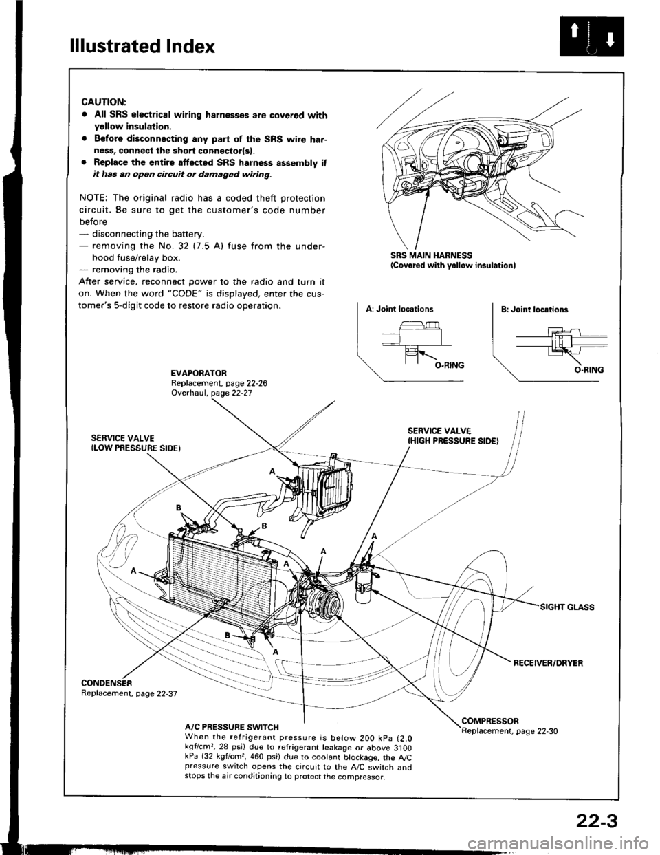
lllustrated Index
CAUTION:
. All SRS electrical wiring harnossos are cover€d withyellow insulation.
. B€fors disconnacting any part of the SRS wire har-ness, connsct the 3hort connsctor(s).. Replace the entirs affscted SRS harness assembly itit has an open circuit or damaged wiring.
NOTE; The original radio has a coded theft protection
circuit. Be sure to get the customer's code number
before- disconnecting the battery.- removing the No.32 (7.5 A) fuse from the under-
hood fuse/relay box.- removing the radio.
After service, reconnect Dower to the radio and turn it
on. When the word "CODE" is displayed, enter the cus-
tomer's 5-digit code to restore radio operation.
SRS MAIN HARNESSlcover€d with yellow insulationl
EVAPORATORReplacement, page 22-26Ovethaul. Oase 22.27
SERVICE VALVE(LOW PRESSURE SIDEI
SERVICE VALVEIHIGH PRESSURE SIDE)
RECEIVER/DRYER
CONDENSERReplacement, page 22,37
A/C PRESSURE SWITCHCOMPRESSORReplacement, page 22-30When the refrigerant pressure is below 200 kpa (2.0kqflcm,,28 psi) due to refrigerant leakage or above 3]OOkPa (32 kgf/cm,, 460 psi) due to coolant btockage, the A,/Cpressure switch opens the circuit to the A"/C switch andstops the air conditionang to protect the compressor.
22-3
Page 1074 of 1413
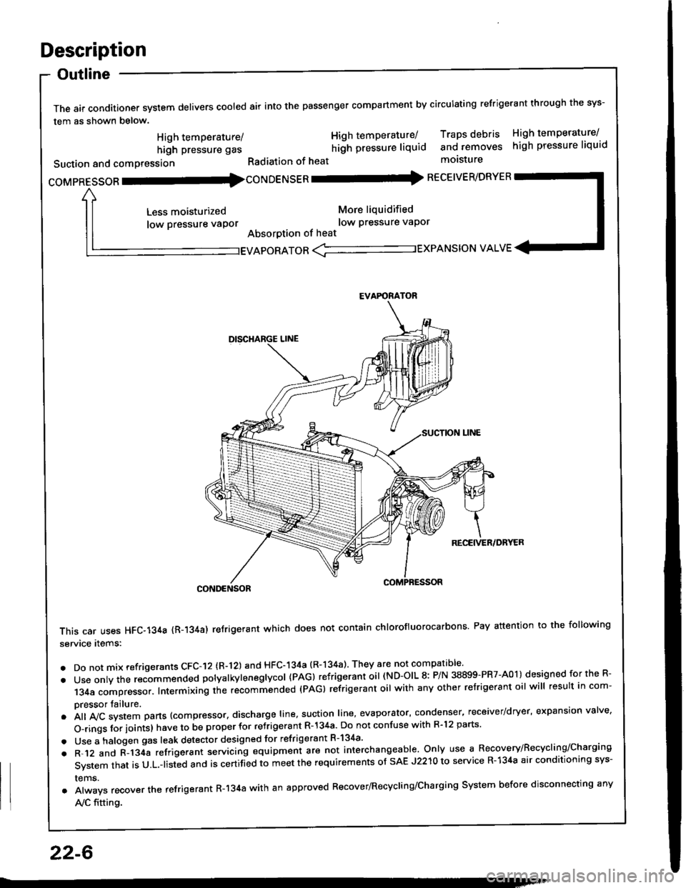
Description
Outline
The air conditioner system delivers cooled air into the passenger compartment by circulating refrigerant through the sys-
tem as shown below.
CONDENSOR
This car uses HFC-134a {R-134a) refrigerant which does not contain chlorofluorocarbons Pay attention to the following
service items:
. Do not mix refrigerants CFC-I2 (R-l21 and HFC-134a (R-134a) They are not compatible'
. Use onty the recommended potyatkytenegtycol {PAG) refrigerant oil (ND-OIL 8: P/N 38899-PR7-A01) designed for the R-
134a compressor. Intermixing the recommended (PAG) refrigerant oil with any other refrigerant oil will result in com-
pressor tailure.
.A||lvcsystemparts(compressor.dischargeIine,suotionIine,evaporator,condenser.receiver/dryer,expansionva|ve.
o-ringsforioints}havetobeproperforre'rigerantR-l34a.DonotconfusewithR.l2parts.
. Use a halogen gas leak detector designed for refrigerant R-134a'
. R-.12 and C-l34a refrigerant servicing equipment are not interchangeable. Only use a Recovery/Recyclins/Charging
System that is U.L.-listed and is certifLd to meet the requirements of sAE J2210 to service R-134a air conditioning sys-
rems.
. Always recover the refrigerant R-134a with an approved Recover/Recycling/Charging System before disconnecting any
A,/C fitting.
coMpRESsoR -coNDENSER - RECEIVER/DRYER
High temperature/
high pressure gas
Suction and comPression
Less moisturized
low pressure vaPor
High temperature/ Traps debris High temperature/
hilh pressure liquid and removes high pressure liquid
Radiation of heat molsture
More liquidified
low Pressure vaPor
Absorption of heat
EVAPORATOR <-'----------.- EXPANSION VALVE
EVAFORATOR
22-6
Page 1091 of 1413
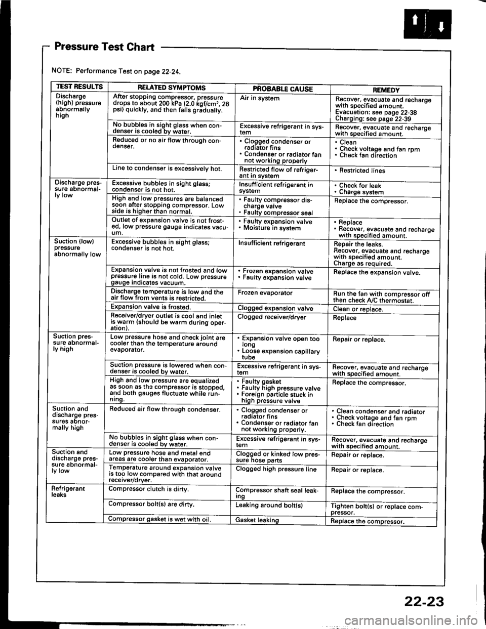
Pressure Test Chart
NOTE: Performance Test on page 22-24.
TEST RESULTSRELATED SYMPTOMSPROAABLE CAUSEREMEDYDischsrge(high) pressureabnormallynrgn
AftEr stopping compressor, pressuredrops to about 200 kPa (2.0 kof/cmr. 28psi) quickly, and then falls gr;dua y.
Air in systemRecover, evacuate and recharqowith sDecified amount. -
Evacuation: see Daqe 22-38Charoino: se6 D;op--2?-?qNo bubbles in sight g16ss when con-denser is cooled bv water.E-\cessive refrigerant in sys-Recover, evacuate and recharqewith specitied amount. -
Reduced or no air flow through con-oenser.Clogged condenser orradiato. finsCondenser o. radiator fannot working properly
CleanCheck voltage and fan rpmunecK lan ofeclton
Line to condenser is excessivelv hot.Restricted flow of refriger-ant In syslem. Restricted lines
Discharge pres-su re abnormal-Excossive bubbles in sight glass;condenser is not hot.Insuff icient refrigerant insyslemCheck for leakCharge systemHigh and low pressures are balancedsoon after stopping compressor. Lowside is higher than normal,
Faulty compressor dis-cnarge vaNsFaulty compressor seal
Replace the compressor.
Outlet of expansion vslve is not frost-ed, low pressure gauge indicates vacu-um,
. Faulty expansion valve. Moisture in sysiem. Replace. Recover, evacuate and recharoewith specified amount. -
Suction (lowlpressureabnormally low
Excessive bubbles in sight glass;conqenser rs not hot_Insuff icient ref rigerantReoair the leaks.Reaover, evacuate and recharoewith sDecifisd amount. -
Charqe as required.Expansion valve is not trosted and lowpressur€ line is not cold. Low pressuregauge Inorcates vacuum.
Frozen expansion valveFaulty expansion valveReplace the expansion valve.
Discharge temperaturg is low and theair flow from vents is restricted.Froren evaporatorRun the tan with comoressor oftthen check Ay'C thermostat.Expansion valve is frost€d.Clogged expansion valveCl€an or replace.Receiver/dryer outlet is cool and inletisrryarm (should be warm during oper-Clogged r€ceiver/dry€rReplace
Suction pres-su re abnormal-ly high
Low pressure hose and check joint arecooler than the temDeraturo aroundevaDorator.
'
ffin"nsion u"lu" oD"n too
. Loose expansion capillary
Repair or replace.
Suction pressure is lowered when con-denser is cooled by water,Excessive refrigerant in sys-remRecover, evacuate and recharqewith sDecifi€d amount. -
High and low pressure are equalizedas soon as the compressor is stopped,and both gauges fluctuate while run-nrng.
Faultv oasketFaulty Figh pressure valveForeign particle stuck inhigh pressure valve
Replace the compressor.
Suction anddischarg€ pres-sufes aonor-mally high
Reduced air flow through condenser.. Clogged condenser orradiator fins. Condenser or radiator fannot working properly.
Clean condenser and radiatorCheck voltage and fan rpmCheck fan direcrion
No bubbles in sight glass when con-cl€nser is cooled bv water.Excessive refrigerant in sys-remRgcover, €vacuate and recharoewith sp€cified amount.Suction snddischarge pres-su r€ abnormal-
Low pressure hose and metal endafeas are cooler than evaDorator.Clogged or kinked tow pre€-sure nos€ pansFepair or replace.
Temperature around expansion valveis too low compared with that aroundrecerver/orver.
Clogged high pressure lineRepair or replace.
Refrig€rantleaksCompressor clutch is dirty.Compressor shaft seal leak-IngReplace the comDressor.
Compressor bolt(s) are dirty.Leaking around bolt(s)Tighten bolt(sl or replace com-pressor.Compressor gasket is wet with oil. IGasket leakingReplace the compressor.
22-23
Page 1106 of 1413
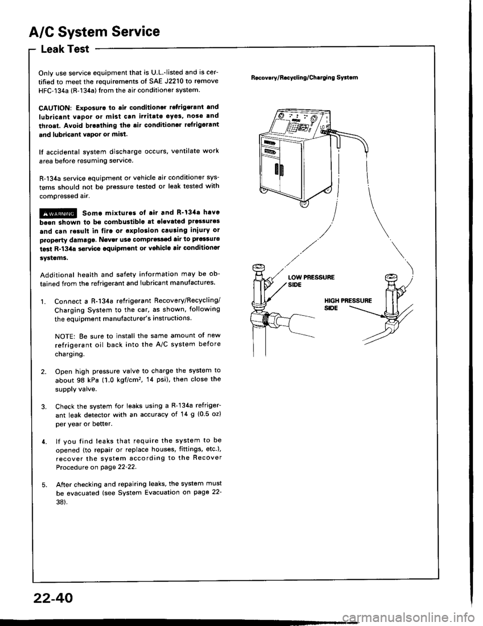
A/C System Service
Leak Test
Only use service equipment that is U.L.-listed and is cer-
tified to meet the requirements of SAE J2210 to remove
HFC-134a (R-134a) from the air conditioner system.
CAUTION: Exposura to air condition ratrigerant and
lubaicant vapor or mist can irritato oyes. nose and
throat. Avoid br€athing tho sir conditionsr reftigolant
and lubricant vapor or mist.
lf accidental svstem discharge occurs, ventilate work
area before resuming service.
R-134a service equipment or vehicle air conditioner sys-
tems should not be pressure tested or leak tested with
comoressed air.
@ some mixturos ot air and R'13'la have
b.6n shown to b€ combustible at glsvated pressur€s
and can result in firo or sxplo3ion causing iniury or
proporty damage. Ngvar uso compress€d tir to pro33ure
tost R-134a $rvics oquipmont or vohicl€ air Gonditionsr
systcms.
Additional health and satetY information may be ob-
tained from the refrigerant and lubricant manufactures'
1. Connect a R-134a retrigerant Recovery/Recycling/
Charging System to the car. as shown, following
the equipment manufacturer's instructions.
NOTE: Be sure to install the same amount of new
refrigerant oil back into the A/C system before
chargtng.
2. Open high pressure valve to charge the system to
about 98 kPa (1.0 kgf/cm'�, 14 psi), then close the
supply valve.
3. Check the system for leaks using a R-134a refriger-
ant leak detector with an accuracy of '!4 g {0.5 oz)
per year or better.
4. lf you find leaks that require the system to be
opened (to repair or replace houses, fittings, etc.),
recover the system according to the Recover
Procedure on page 22-22.
5. Aiter checking and repairing leaks, the system must
be evacuated (see System Evacuation gn page 22-
38).
Rocov.ry/R.cycling/Ch.tging Sy3tcm
LOW PRESSURESIDE
HIGHSIDE
22-40
Page 1120 of 1413
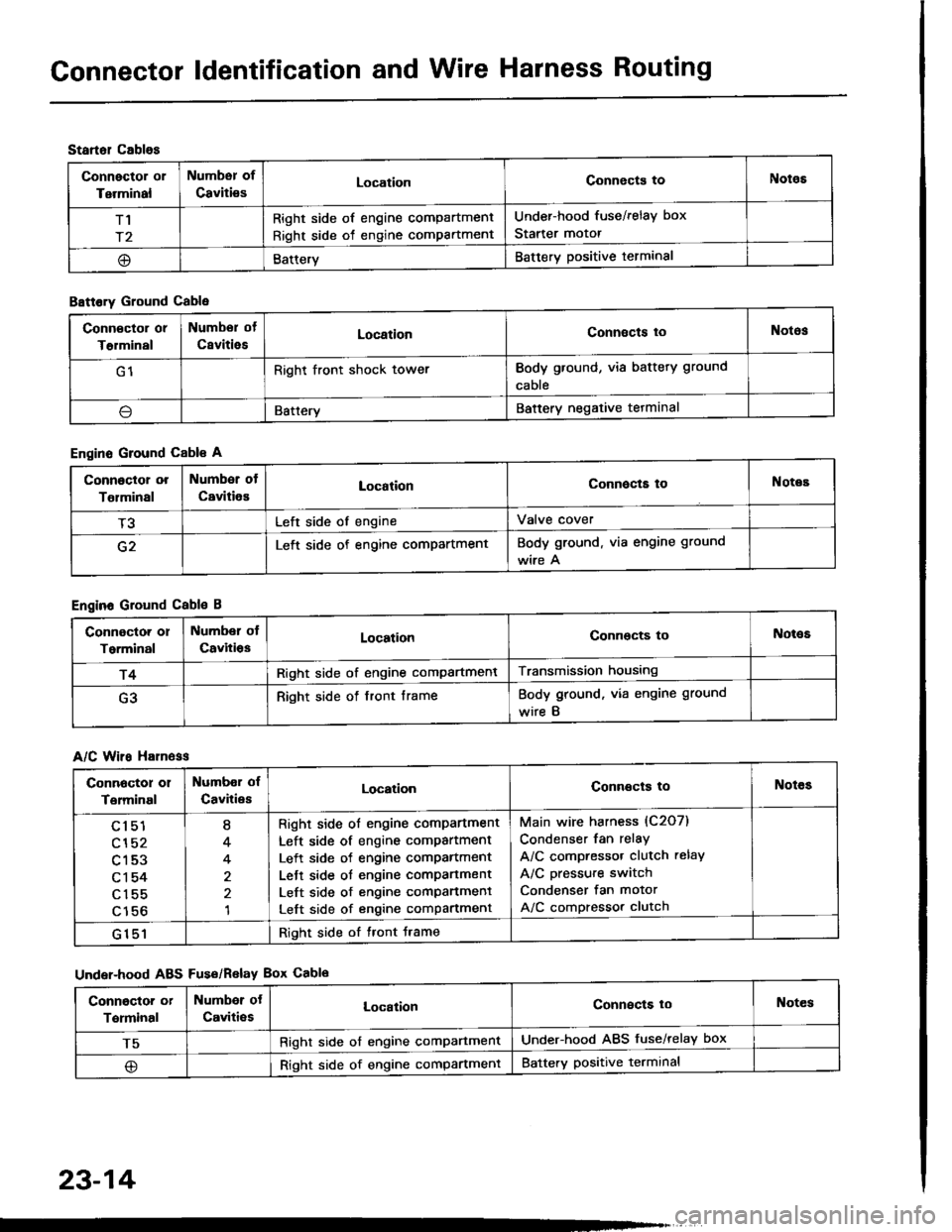
Gonnector ldentification and Wire Harness Routing
Startol cablos
Connector or
Terminal
Numbsr of
CavitiesLocationConnects toNotos
T1
r2
Right side of engine compartment
Right side of engine compartment
Under-hood fuse/relay box
Starter motor
@BatteryBattery positive terminal
B8ttory Ground Cable
Engine Ground Cable A
Engine Ground Cable B
A/C Wiro H81n6ss
Under-hood ABS Fus€/Relav Box Cablo
Conn€ctor or
T€rminal
Numbor of
CsvitiesLocationConnects toNotos
G1Right front shock towerBody ground, via battery ground
cable
\lBatteryBattery negative tetminal
Connoctor or
Tolminal
Number of
CavitiesLocationConnocta toNotes
T3Left side of engineValve cover
G2Left side of engine compartmentBody ground. via engine ground
wire A
Connoctor or
Torminal
Number ol
CavitiosLocationConnocts toNot€s
r4Right side of engine compartmentTransmission housing
G3Right side of front frameBody ground, via engine ground
wire B
Connoctor 01
Terminal
Numbor of
CavitiesLocationConnects toNotes
cl51
cl52
c153
c1 54
c155
c156
I
4
4
1
Right side ol engine comPartment
Left side of engine compartment
Left side of engine comPartment
Lett side ot engine compartment
Left side of engine comPanment
Left side of engine compartment
Main wire harness (C2O7)
Condenser fan relay
A/C compressor clutch relay
A/C pressure switch
Condenser fan motor
A/C compressor clutch
G151Right side of tront Jrame
Conngctor or
Terminal
Numbor ot
Caviti€sLocalionConnects loNotes
T5Right side of engine comPartmentUnder-hood ABS fuse/relay box
@Right side of engine compartmentBattery positive terminal
23-14