Page 463 of 1413

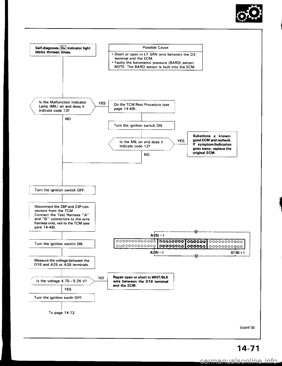
Disconnect lhe 26Pand 22P con-nectors trom the TCMConnect the Test Hahess "A"
and "D" connectors to the wireharness only, not to th€ TCM {seepare'14-49).
Possible Cause
. Short or open in LT GRN wire between the D3terminal and the ECM.. Fauky the barometric pressure {8ARO} sensor.NOTE: The BARO sensor is built into lhe ECM.
ooooooooooooo
oooooooooooo0oOOqgopg I,oiOOOOol ooo ooooooooooocqooo:Joo.oipggl o oooooo o 9ooTurn the ignition swirch ON.
Measure the voltage between theD18 and A25 or A26 terminals.
ls the voltage 4.75-5.25 V?
Turn the ignition swith OFF.
A25t- |
Soll-diagnosis Lq! indicator lightblinks thirtoon tim6.
ls rhe Malfunction lndicatorLamp (MlL) on and does itindicate code 13?
Do the TCM Rest Procedure (seepage 14-49).
Turn the ignition switch ON.
Substituto a known-good ECM and rechock.ll symptom/lndicationgoos away, .oplace theoriginal ECM.
ls the MIL on and does itindicare code 13?
Turn the ignition switch OFF.
Ropair opon or short in WHT/BLKwir6 botwoon th€ D18 to.minaland tho EcM.
fo page 14-72
14-71
Page 465 of 1413
S.fdl.enorl! L&l indicdor lighlblinks fourtoon tlmoa.
ls the Malfunction IndicatorLamp (MlL) onl
Stan the ongine and warm it upto normal operating temperature{th€ radiator lan com€s on).
Shift to E position,
Turn rhe ignition switch OFF.
Possible Cause
. Sh"rt ". "e"" i" FAS |YEU ,"rirt. Fsulty ECM.
Connect the Test Harness be-tween the TCM and connociors{see page 14-491.
Turn the ignition switch ON andwsit for at least two seconds.
o oooooo ooo ooo l.tto.oodooo l:,gEoo.ottl o ooooo oooo o
o oooo oooooooo l:OOOO OO 60 l.,OO{tO.O6,'l o oooooooooo
Measure lhe voltage betwgan thso16l+ ) and A25 or A26(- | tor-mrnals.
lcont'd)
Ropair tho PGM-FI Syrtom lloo..ctlon 111.
Chock for looro TCM connoctora.lf noco$ary, subatituta a known-good TCM and .ech€ck.ls thoro approx. 5 V?
Turn the ignition switch OFF.
Dkconnect the Test Harness fromthe TcM.Leave connect€d to car harness.
Turn the ignition switch ON.
fo page 14-74
14-73
Page 469 of 1413
@ indic"to, light i8 on st6sdyInot blinkingl whenevor the ioni-tion switch is ON.
Disconnect the 26P connectorfrom the TCM.Connect the Test Harness "A"
connector to the wite harnessonly, not to the TCM (see page14-49).
Turn the ignition switch ON.
Measure the voltage between theA8 terminal and body ground.
Ropair shon to power in GRN/BLKwiro botwoen A8 terminal andgauge assembly.
Check for a sho.t to ground on thePNK/GRN wi.e. ll th€ wir. is OK,roplac€ the A/T gear poaition in-dicator.
Turn the ignition switch OFF.
ls there voltage?
Connect the Test Harness "A"
conneclor to the TCM.
Measure the voltage between the417 terminal and body groundwith the selector lever in anv oo'sition other than El.
ls there volrage?
ReDlace tho TCM.
o o o o oo o oo o oo o l:qssoo9pc,I:oocto:osil o o o oo o o o o oooooQoooooooooo oo o oooo ooo
{cont'd)
14-77
Page 470 of 1413

Electrical Troubleshooting
Troubleshooting Flowchaft (cont'dl
Does the @ indicatorcome on?
ls there baftery voltage?
YES
lighr
I A25
| | o ooooo o oo o ooo r:sjc.o.sl'1*st,li*os.s.4tcl ooo oo oooooo I
I I o o o o o o o o o o o o q lifrif.S..n${5git:li$gg-:aiiigitll o o o o o o o o o o o I|--.-T..-I a26
+d
+
I + )A23 A25l - l
(+ tA24 426(- |t\@
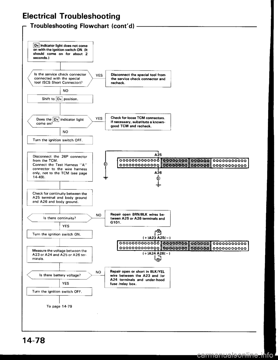
Lq4 indicator light do6s not comeon with the ignition switch ON. (ltshould come on Ior about 2seconds.l
ls the service check connectorconnected with the specialtool ISCS Short Connectod?
Diaconnect tho spocial tool fromth6 sgrvice check connoctor andrecheck.
Check {or loos6 TCM connoctors.lf necessaw, substitute a known-good TCM and recheck.
Turn the ignition switch OFF.
Disconnect the 26P connectorfrom the TCM.Connect the Test Harness "A"
conneclor to the wile harnessonly, not to the TCM (see page14-49).
Check for continuity between theA25 terminal and body groundand A26 and body ground.
R€pair open BRN/BLK wires be-twe6n A25 or A26 torminals andG 101.
Turn the ignition switch ON.
Measure the voltage between theA23 or A24 and A25 or A26 termrnals-
Repaii open or short in BLK/YELwire between tho A23 and /ot424 terminals and underhoodtuse /relav box.
Turn the ignition switch OFF.
To page 14-79
14-78
Page 471 of 1413
Connect the Test Harness "A"
connector to the TCM.
Turn the ignition switch ON.8e sure that voltage is availablefor 2 seconds between thg A8 tor-minal and A25 or A26 terminal.
Chrck for opon or rhort in GR /8LK wirc bctw.on th. A8 termi-nal and tha gauOa arrambly.
Turn the ignition switch OFF.
Disconnect the Test Harness "A"
connector from the TCM.
Check for continuity between theA8 terminal and the GRN/BLKwire at tho gaugo assgmbly (see
section 23).
B.p.ir op.n in GRI{/BLK wi.. bo-lwaen the A8 terminal and th.gauga 6aaombly.
Ch€ck for loor6 TCM conn6ctor3.Check the A/T goa. polition
awitch. ll noc€$ary, subrtitutg aknown-good TCM .nd rochock.
ooooooooooo
ooooooooooo
oooooooooooo
oooooooooooo
a26t - |
A8(+)
(cont'd)
14-79
Page 640 of 1413
7.
Connect the ignition switch wire connectors to the
under-dash fuse/relav box.
Install the combination switch and turn signal can-
celing sleeve onto the steering column.
NOTE: Be sure the wires are not caught or pinched
by any parts when installing the combination
switch.
TURN SIGNAL CANCELINGSLEEVE
Install the cable reel onto the steering column, then
connect the SRS main harness and cable reel wiro
harness and install the connector holder.
NOTE: Align the slot in the cable reel with the pro-
jection on the canceling sleeve.
coMatNATroN swncH
UPPER COLUMN COVER
9. Installthe column covers.
scREws
lnstall the driver's knee bolster.
lnstall the lower cover.
Installthe steering wheel {see page '17-26).
10.
11.
't2.
17-33
Page 1083 of 1413

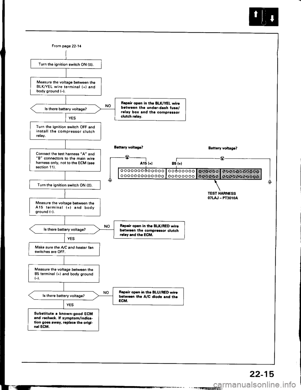
Frcm page 22-11
Bdt ry vohro.?
_@_____-l
Turn the ignition switch ON (lI).
M€asure the voltage betweon th6BLK/YEL wire terminsl {+) andbody ground (-).
R.p.i. opcn in th. 3LX/YEL wirrbalwarn tha undar.da3h tuaa/.clay box and iha como.aaao.clutch rahy.
ls there battery voltage?
Turn the ignition switch OFF andinstall the comprossor clutchrelay.
Connect the test harness "A" and"8" conoectors to th6 main wireharness only, not to the ECM (s6gsection 11).
Turn th6 ignition switch ON (II).
Measure the voltagG between theA15 terminal (+) and bodyground (-1.
R.prir op.n in th. BLK/RED wirtb.twran the compraa.or clotch..1.y .nd th. ECM.
Make sure the A/C and heate. tenswitch6s are OFF.
Measure tho voltage b€tween the85 terminsl (+) and body ground(-).
R.p.ir op.n in th. BI-U/RED wir.b.tw.rn th. A/C diod. .nd th.CCM.
Sub.titute r known-good ECMand rocheck. lt lymptom/indicr-tion go€3 rwry, rapbca th. origi-nrl ECM.
Blttary vohago?
r_--@_Bs {+)
TEST HARNESS07t4, - PT3010a
" , -1llltf,'tfrSfiiwiafi
22-15
Page 1154 of 1413
Fuses
Under-dash Fuse/Relay Box
c918lTo root wiro harness (C661llc919
lTo dashboard wire harness (C55'l )lc920lTo lurn signal/hszard .elayl
c928lTo SRS luso block {C931}l
cg22lTo powor window rclaylAuxili.ry fulo holdei
r: Not usod.: Canadd| ): S6dan
O: C923 loplion lBATll
@: C924 toption (BATll
O: C925 toption llc2)1
@r C926 loption {No. 19 fusoll
@: C927 loption {ACC)I
r.-------l
SRS FUSE BLOCK
c929
J To SRS main II harnass {C8011 I
c930
I To ignitionl
I switch i
c931
I To und€rdash II fuso/rolay box {C928) I
Elnnnr.'trJnnrJn12 13 14 15 16 17 18 19 20 21
UUIJUIJULJLILIIJ
n|:]nnnnnn r''l
1 2 3 t4l 5 6 (7) 8 9.
LIIJLIULJUUU U
22 23
UIJ
N11
10 11
LILI
23-48