Page 1150 of 1413

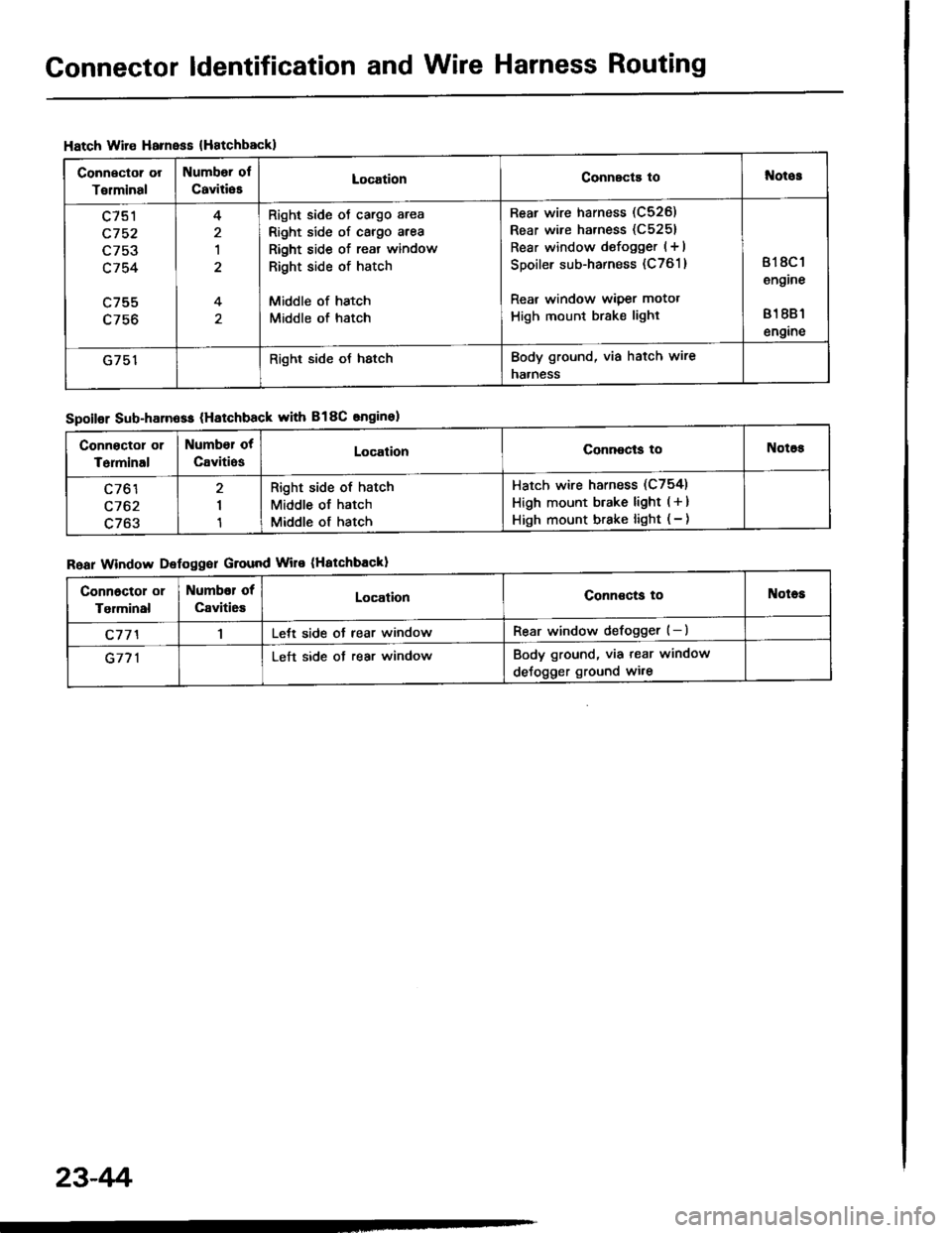
Connector ldentification and Wire Harness Routing
Hatch Wire Harnsss {Hatchbackl
Connector or
Torminal
Numbor ol
CaviliesLocationConnscts tol{otos
c751
c752
L/5J
c754
c755
4
1
4
Right side oJ cargo area
Right side of cargo area
Right side of reat window
Right side of hatch
Middle of hatch
Middle of hatch
Rear wire harness (C526)
Rear wire harness (C5251
Rear window defogger (+ I
Spoiler sub-harness (C761 )
Rear window wiper motot
High mount brake light
818C 1
engine
81 881
engine
G751Right side oJ hstchBody ground, via hatch wire
naaness
Spoilor Sub-harn6ss (Hatchback with B18C snginel
Roar Window Defoggor Ground Wire (Hatchbackl
Connoctor or
Terminal
Number ot
CavitiosLocalionConnocls toNotos
c761
c762
c763
I
1
Right side of hatch
Middle of hatch
Middle of hatch
Hatch wire harness (C754)
High mount btake light ( + )
High mount brake light ( - )
Connoctol or
Tgrminal
Numbor of
Caviti6sLocationConnoctg toNotes
c77'l1Lett side ot rear windowRear window defogger (-)
G771Left side ot rear windowBody ground, via tear window
deJogger ground wi.e
23-4r'i
Page 1185 of 1413
1.
2.
Starter Replacement
Disconnect the negative cable from the batterv.
Remove the intake air duct.
AIR CIEANERHOUS|L
Remove the engine wire harness and startef cablesfrom their brackets.
ENGINE WIRE HARI{ESS
CAALES
4.Disconnect the staner csble from the B terminal onthe solenoid, then the BLK/WHT wire from the Sterminal.
Remove the two bolts holding the staner, then re-move the startef.
UPPER MOUI{TII{G BOLT44 N..h (4.5 kgl.m, 33 lbt,ftl
8 TERMII{AL MOUIITTI{G NUT9 .ln (0.9 kgf.m, 6.5 tbf.ttl
TERMINAL
BLI(AA/HT WIRE
6. Install in the reverse order of removal,
23-79
Page 1219 of 1413
Gauge Assembly
Component Location Index
CAUTION:
a All SRS electrical wiring harnosses are cov€rod withyellow insulation.
a Bofore disconnecting any prn ot th€ SRS wire har-ness, connect tho short connector(sl.a R€place th6 entirs affGcted SRS halne$ assembly ifit has an open circuit o? damaged wiring.
SRS MAIN HARNESS{Cov.r6d with yollow inrularionl
GAUGE ASSEMBLYGauge Location Index, page 23-114Indicator Location Index, page 23-1 14Terminal Location Index, page 23-114Bulb Location. page 23-'l 15Disassembly. page 23-1 19Removal, page 23-118
FUEL GAUGE SENDING UNtTTest, page 23'124Repfacemenr, page 23-124
VEHICLE SPEEO SENSOB IVSS}Test, page 23-120fnput Test. page 23-120Repfacement, page 23-122
PARKITTG BRAKE SWITCHTest, page 23-127
BRAKE FLUID LEVEL SWITCHTesr, page 23-127
EI{GINE OIL PBESSURE SWITCHTest, page 23-122
ENGINE COOLANT TEMPERATURE IECTI GAUGESENOING UNITTest, page 23-126
(C61'ios tho SBS indicator signal)
23-113
Page 1226 of 1413

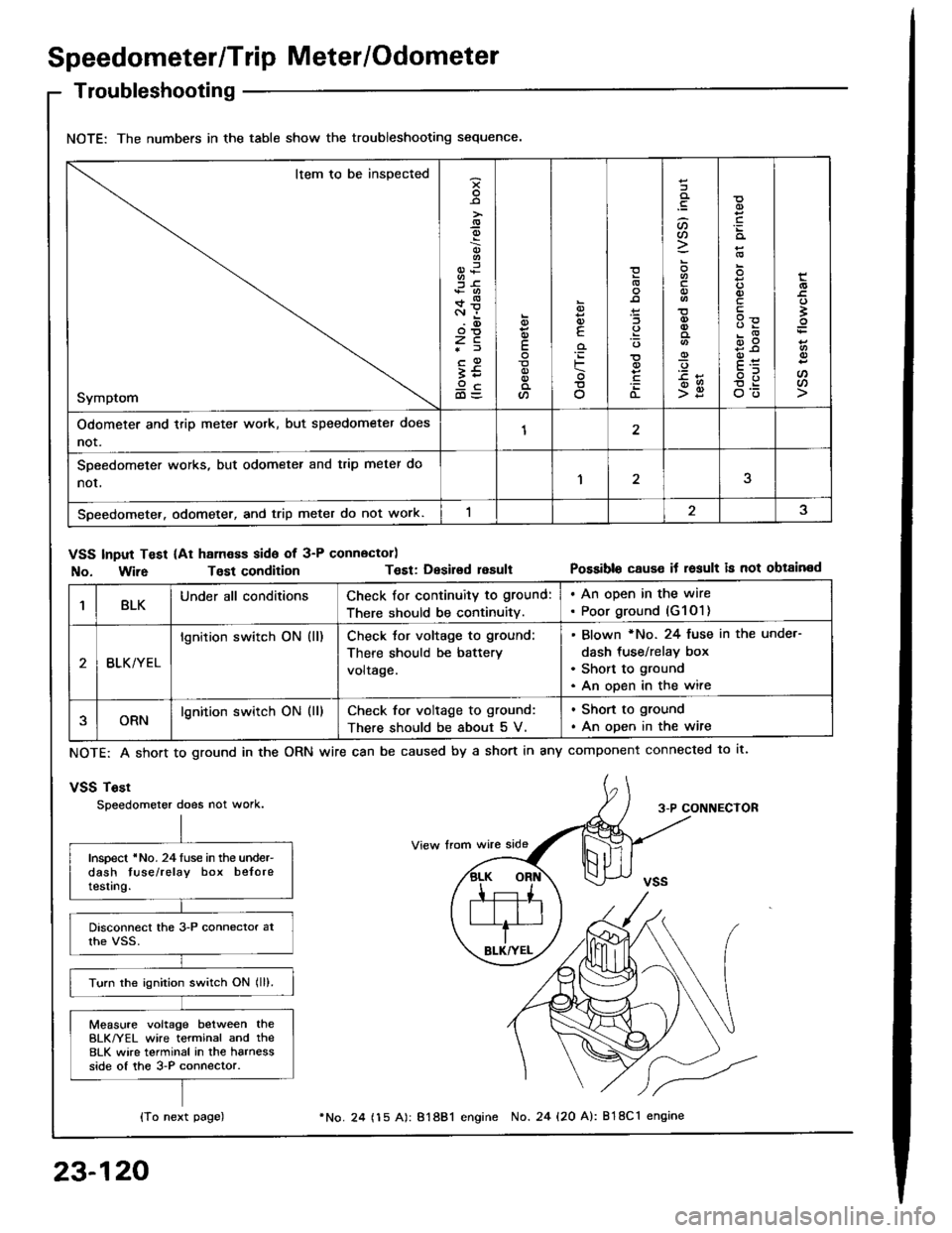
Speedometer/Trip Meter/Odometer
Troubleshooting
NOTE: The numbers in the table show the troubleshooting sequence.
Item to be inspected
Symptom
-9
;6+*c.r i.(D
zc*f
;59cd)=
E
a
6
E
'iF
o
(L
:lt)a
o
-9
>g
q)
qlv
E
'
E
oo
Odometer and trip meter wotk, but speedometer does
not.12
SDeedometer works, but odometer and trip meter do
nor,1
Speedometer. odometer, and trip meter do not work.
VSS Input Test (At ham€ss side of 3-P connector)
No. Wir6Tost conditionT€st: Desirsd resultPossible cause it result is not obtained
1BLKUnder all conditionsCheck for continuity to ground:
There should be continuity.
. An open in the wire. Poor ground (G1O1)
BLK/YEL
lgnition switch ON (ll)Check tor voltage to ground:
There should be battery
voltage.
Blown *No. 24 fuse in the unde.-
dash tus€/relay box
Short to ground
An open in the wire
ORNlgnition switch ON (ll)Check for voltage to ground:
There should be about 5 V.
. Shon to ground
. An open in the wire
NOTE: A short to ground in the
vSS Tost
Speedometer does not work.
ORN wire can be caused by a short in any component connected to lt.
3-P CONNECTOR
Inspect 'No. 24luse in the under-dash tuse/relay box beloretesting.
Turn the ignition switch ON lll).
Measure voltage between theBLK/YEL wire terminal and the8LK wire terminal in the harnessside of the 3-P connector.
{To next page)
23-120
24 (15 A): 81881 engine No. 24 {20 A): 818C1 engine
Page 1243 of 1413

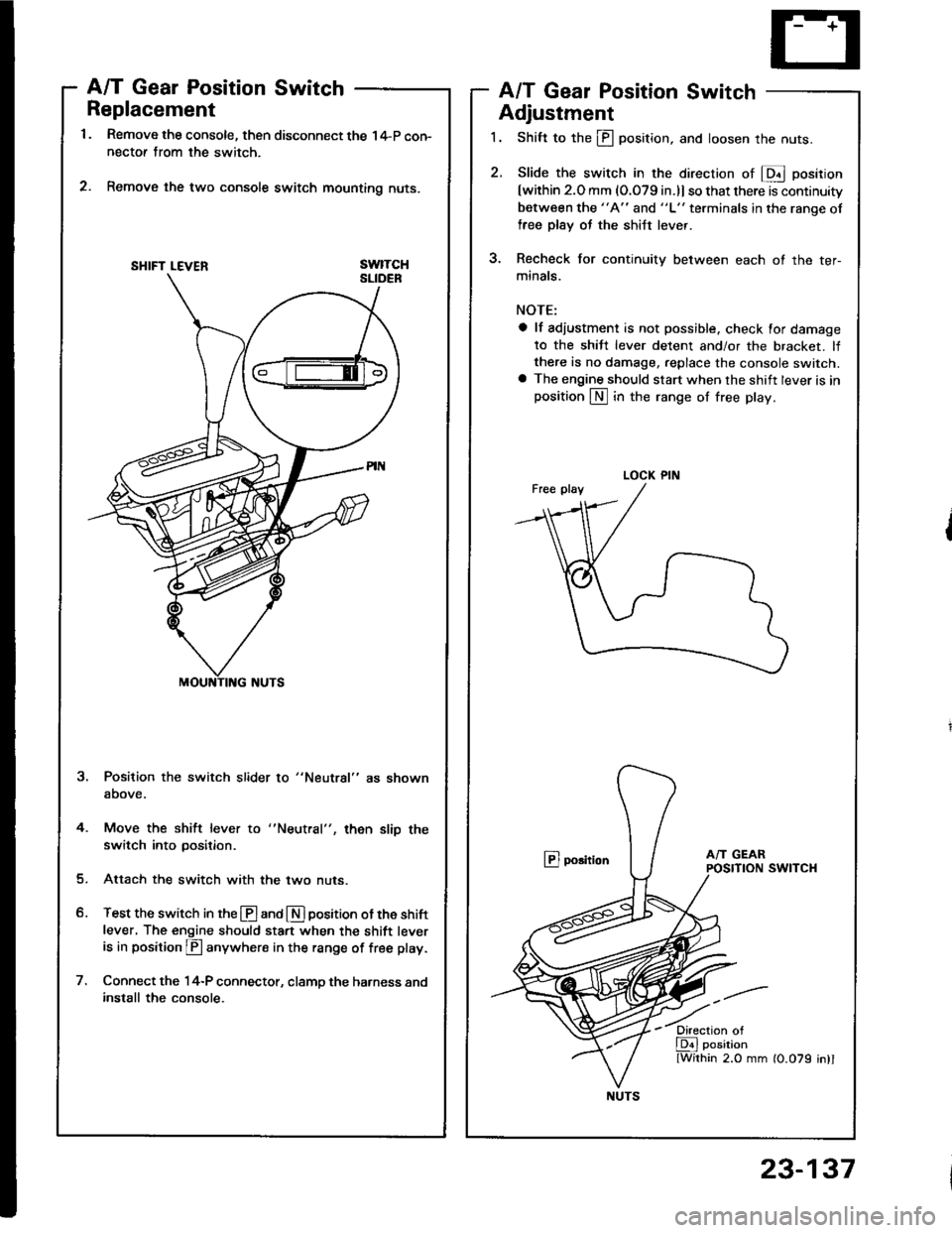
Replacement
Remove the console, then disconnect the 14-P con-nectof from the switch.
Remove the two console switch mounting nuts.
swtTcH
A/T Gear Position SwitchA/T Gear Position Switch
Adjustment
1. Shift to the ill position, and loosen the nuts.
2. Slide the switch in the direcrion of E position
[within 2.O mm (O.079 in.)l so that there is continuity
between the "A" and "L" terminals in the ranqe of
free plsy oJ the shiJt lever.
3. Recheck for continuity between each ot the ter-
minals.
NOTE:
a lf adiustment is not possible. check for damage
to the shiJt lever detent and/or the bracket. lfthere is no damage, replace the console switch.a The engine should start when the shift lever is inposition LN] in the range of free play.
@ porition
Position the switch slider to "Neutral" as shown
above.
4. Move the shift lever to
switch into position.then slip the
Attach the switch with the two nuts.
Test the switch in the @ and E] position ot the shift
lever. The engine should sta.t when the shift leveris in position p anywhere in the range of free play.
Connect the 14-P connector, clamp the harness andinstall the console.
SHIFT LEVER
LOCK PIN
NUTS
23-137