1994 HONDA INTEGRA connector
[x] Cancel search: connectorPage 1398 of 1413
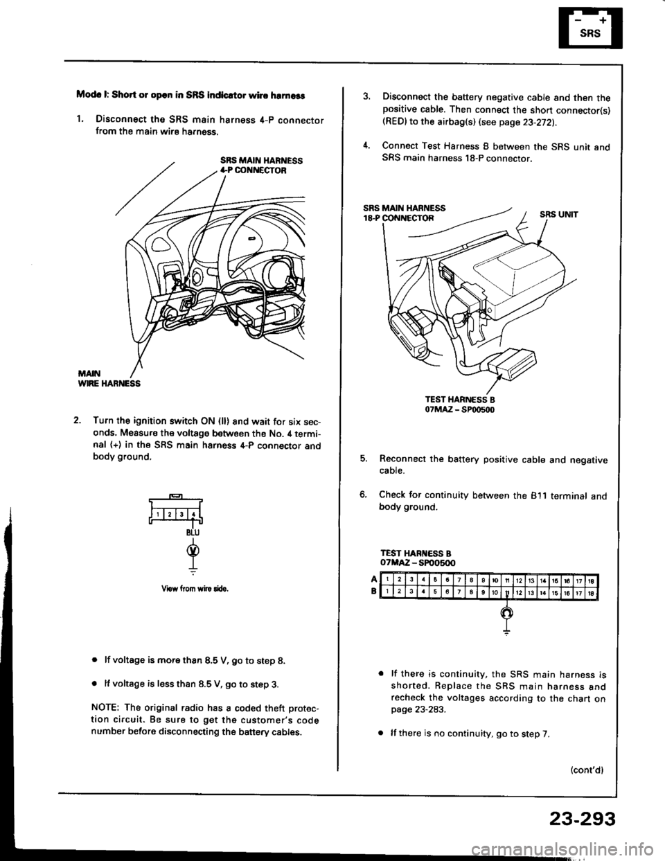
Modc l: Short 01 opcn in SRS indicrtor whc hrrnaas
1. Disconnect tho SRS main harness 4-p connectorfrom the main wirs harn6ss.
WIRE HABNESS
2. Turn the ignition switch ON (ll) 8nd wait for six sec-onds. Measu.s the voltage between ths No. il termi-nal (+) in the SFS main harness 4-P connector andbody ground,
. lf voltage is more thsn 8.5 V, go to step 8.
. It voltage is less than 8.5 V, go to step 3.
NOTE: The original radio has a coded theft protec-
tion circuit. Be sure to get the customer's codenumber before disconnecting the banery cables.
*-
F4
BLU
d.L
Vrow llom wi|! rftro.
Disconnect the battery negative cable and then thepositive cable. Then connect the sho.t connector(s)(REDlto the airbag(s) (see page 23-272).
Connect Test Harness B between the SRS unit andSRS main harness 18-P connector.
5. Reconnect the battery positive cable and negativecaote.
6, Check for continuity between the 811 terminalbody ground.
lf there is continuity, the SRS main harness isshorted. Replace the SBS main narness anorecheck the voltages according to the chart onpage 23-283.
lf there is no continuity, go to step 7.
(cont'dl
23-293
Page 1399 of 1413
Supplemental
Troubleshooting(cont'dl
RestraintSystem (SRSI
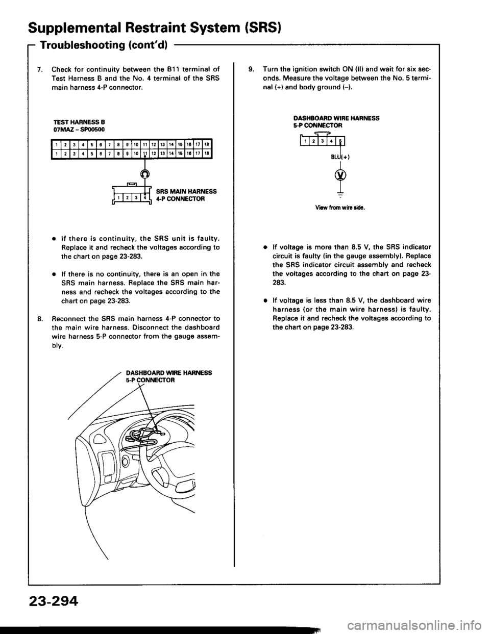
7.Check for continuity between the 811 terminal of
Test Harness B and the No. 4 terminal of the SRS
main harness 4-P conngctor,
oTurn ths ignition switch ON {ll} and wait for six sec-
onds. Measure the voltage between the No. 5 termi-
nal (+) and body ground (-).
TEST HARNESS B07MAZ - SF|D500
OASHSOARO IVIRE HARNESSs.PCO ECTOR
Vraw from sil! rira,
8.
. lf there is continuity, the SRS unit is faulty,
Replace it and recheck the voltages according to
the chart on page 23-283.
. lf there is no cootinuity. there is an open in the
SRS main harness. Replace the SRS main h8r-
ness and recheck the voltages according to the
chart on page 23-283.
Reconnect the SRS main harness 4-P connecto. to
the main wire ha.ness. Disconnect the dashboard
wire ha.ness 5-P connector from the gauge assem-
Dtv.
lf voltage is mora than 8.5 V, the SRS indicator
circuit is faulty (in the gauge assemblyl. Replace
the SRS indicator circuit assembly and recheck
the voltsges according to the chart on page 23-
243.
lf voltage is less than 8.5 V, the dashboard wire
harness (or th€ main wire harness) is faulty.
Replace it and recheck the voltages according to
the chart on page 23-283.
DASHBOARD WIRE HARNESS5.P OONNECTOR
23-294
Page 1400 of 1413
Airbag Assembly Replacement
@E storc a r.movcd lirb.g rslombty with thcp.d surfaco up, if tho lirbrg is improparly 3iorad frcadown, accidontal d.ploymert could plopcl tha unit withcnough torcr lo causc lariour iniury.
CAUTION:
. Do not inst.ll urld SRS plrts trom lnothar c!1,Whon lepairing, uss only now SRS prrt!.o Carefully inlpcct thc airblg rlrcmbly bltorc you
install it. Do not inst.ll an airbag !$.mbly thrt3how! sign3 of bcing droppcd or improparly hrn-dlod, such as dont!. crack3 or dstormation.. Alwry! koop ths rhort connactor(3l (REDI on thaairbrg{s} whon tho hsrnca3 i! dirconnastld.. Do not diras3ombl! or tamp€l with tha lirbrga$ombly.
NOTE: The original radio has a coded th6ft protection
circuit. Be sure to get the customer's code number
before disconnecting the battery cables.
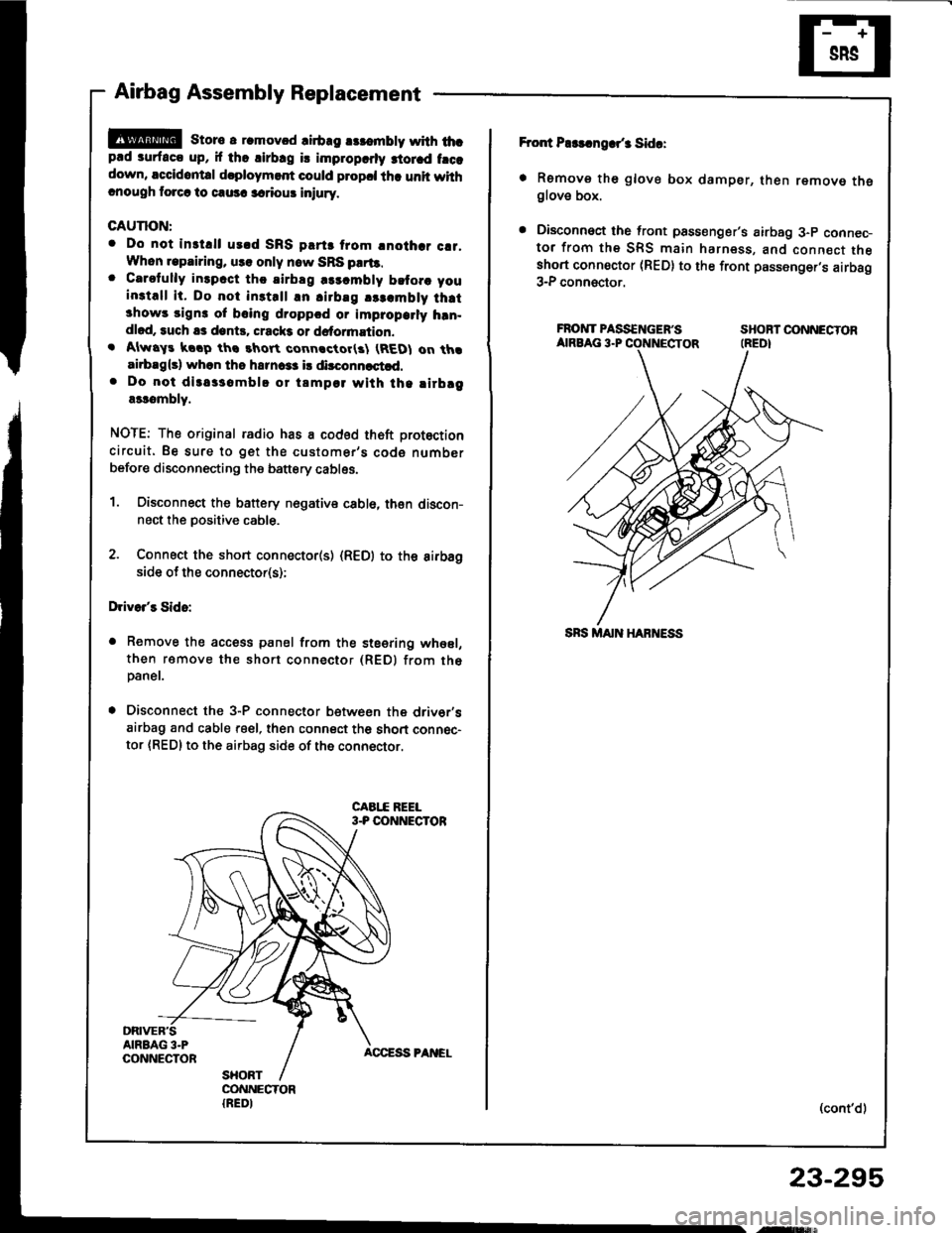
1. Oisconnect the battery nogative cabl6, then discon-nect the positive cable.
2. Connect the short connecto(s) (R€D) to the aifbagside of the connector(s);
Drivo/s Sido:
a Remove the access panel from the steering whesl,
then ramove the short connector (REDI from th6paner.
. Disconnect the 3-P connector betwesn the driv6r'sairbag and cable reel, then connect th6 short connec-
tor {RED} to the airbag side of the connector.
Fror{ P$!.ngar/3 Sida:
. Remove th6 glove box damper, then remove theglove box.
. Disconnoct the front psssenger's airbag 3-p connec-tor from the SRS main harness, and connect theshort connoctor (RED) to the front passenger,s airbag3-P connector.
FROIVTPASS€NGEF'S SHOBTOONNECTORAIRBAG 3.P CONNECTOR (REDI
(cont'd)
23-295
,ry!$,
Page 1402 of 1413
CAUTION: Bo 3uro to in3tsll tho SRS wiring so that it isnot pinchod or intoforing with other car parts.
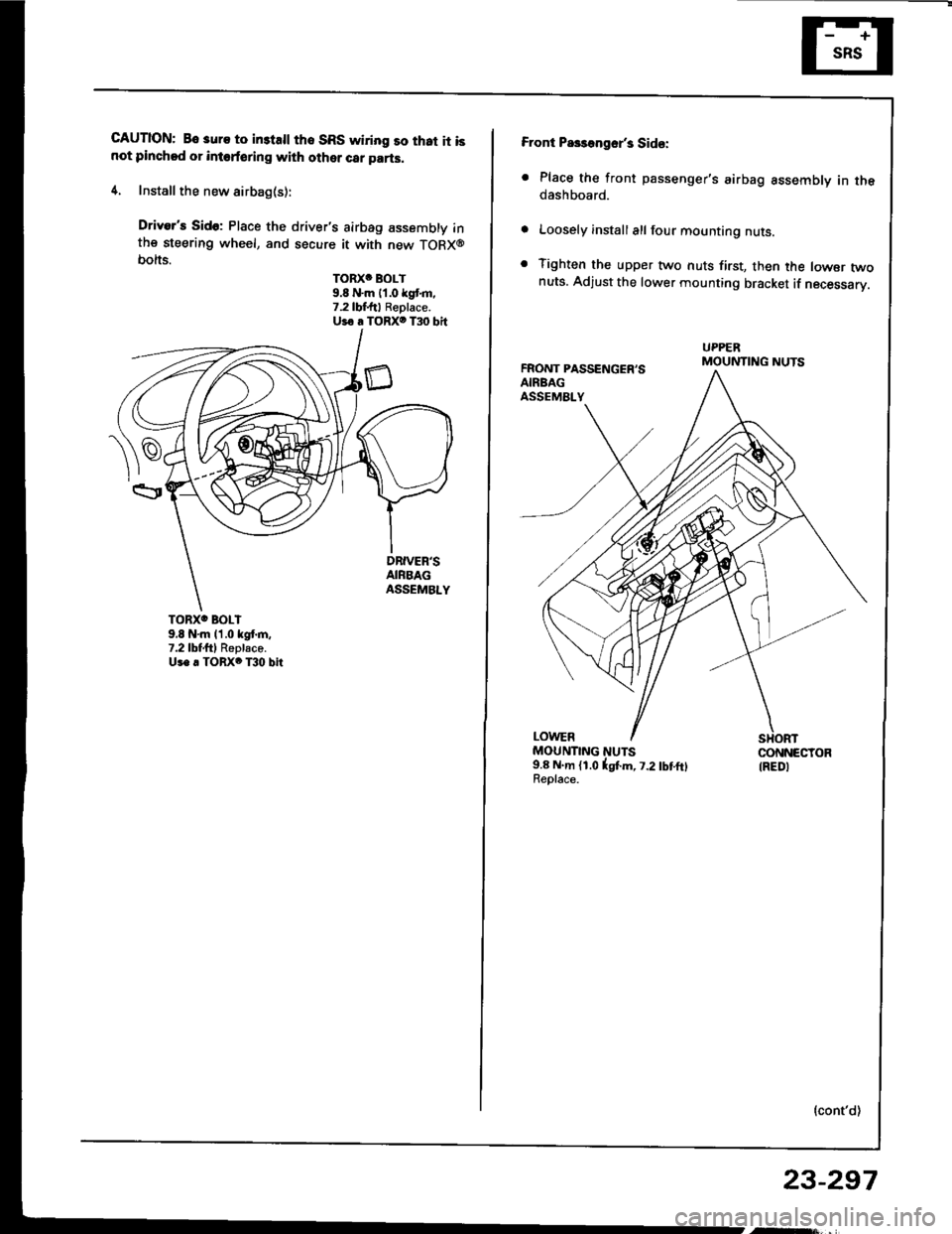
4. Install the new airbag(s):
Driver's Sido: Place the driver's airbag assembly inthe steering wheel, and secure it with new TORX@bolts.
TORXC BOLT9.8 N'm 11.0 kgt m.7.2lbf.ftl Replace.Uio a TORXO T30 bit
TORXO BOLI9,8 N'm l'1.0 kgf.m,7.2lbtftl Replaco.Us. . TORX6 T30 bit
Front Pa$aogsr's Sid€:
. Place the front passenger's airbag assembly in thedashboard.
Loosely install all four mounting nuts.
Tighten the upper two nuts first, then the lowsr twonuts. Adjust the lower mounting bracket if necessarV.
FRONT PASSENGER'SAIRBAGASSEMALY
UPPERMOUNTING NUTS
LOWERMOUNTING NUTS9.8 N.m (1.0lgtm, t.2lbtftlReolace.
CONNECTORIREDI
{cont'd)
23-297
Page 1403 of 1413
Supplemental Restraint System (SRSI
Airbag Assembly Replacement (cont'd)
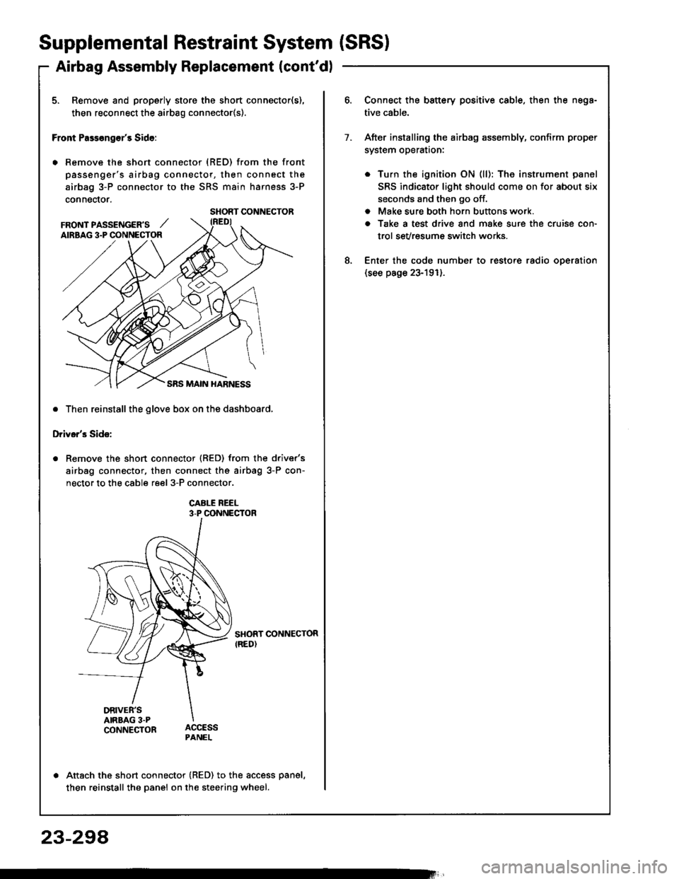
5. Remove and properly store the short connector(s),
then reconnect the airbag connector(s).
Front Pass€ng€r's Side:
. Remove the short connector (RED) from the front
passenger's airbag connector, then connect the
airbag 3-P connector to the SRS main harness 3-P
connector.
. Then reinstall the glove box on the dashboard,
Driver's Side:
Remove the short connector (RED) from the driver's
airbag connector, then connect the airbag 3-P con-
nector to the cable reel 3-P connector.
CABI-E REEL3-P CONNECTOR
SHORT CONNECTORIRED)
DRIVER'SAIRBAG 3.PCONNECTOR
Attach the short connector (RED) to the access panel,
then reinstall the panel on the steering wheel.
SHORT CONNECTOR
FRONT PASSENGER'S ,,'AIRBAG 3.P CONNECTOR
Connect the battery positive cable, then the nega-
tive cable.
After installing the airbag assembly, confirm proper
system operataon:
. Turn the ignition ON (ll): The instrument panel
SRS indicator light should come on for about six
seconds and then go off.
. Make sure both horn buttons work.
a Take a test drive and make sure the cruise con-
trol sevresum€ switch works.
Enter the code number to restore radio oDeration(see page 23-191).
7.
8.
23-294
Page 1404 of 1413
Airbag Assembly Disposal
Before scrapping any airbag(s) (including one in a wholecar to be scrappedl, the airbag must be deployed. t{ thecar is still within the warranty period, before you deplovthe ai.bag, the Acura District Service Manager must giveapproval and/or special instructions. Onlv after the air-ba9 has been deployed (as the result of vehicle collision,for example),it can be scrapped.lf the airbag(s) appear(s) intact (not deptoyed, treat it{them) with extreme caution.Follow this Drocedure:
Doploying the Airbag(sl: In-car
NOTE: lf an SRS car is to be entirely scrapped. itsairbag(s) should be deployed while still in the car. Theairbag(s) should not be considered as salvageablepan(sl and should never be installed in another car.
@ confirm that osch airbsg assembly iss6cursly mounted; oihorwis6. s€voro parsonal iniurycould result from doployment.
1. Disconnect the banery negative cable. then discon_nect the Dositive cable.
2. Confirm that the special tool is functioning properlyby following the check procedure on the label of thetool set box, or on page 23-300,
Driver's Airbag:
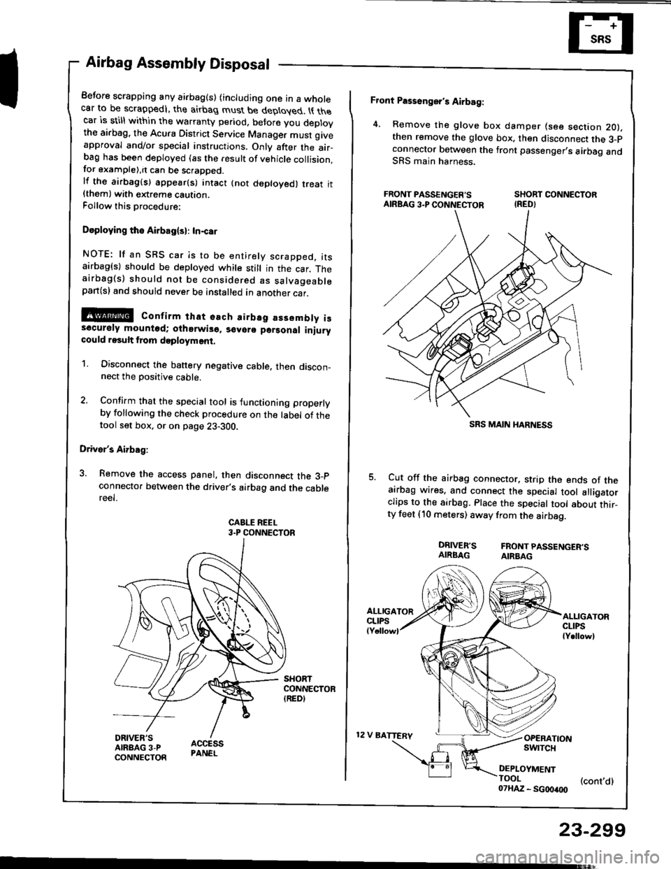
3. Remove the access panel, then disconnect the 3_pconnecto. between the driver's airbag and the cablereel.
CABLE REEL3.P CONNECTOR
Front Passonger's Airbag:
4. Remove the glove box damper (see section 2O).then remove the glove box. then disconnect the 3-pconnector botween the front passenger,s airbag andSRS main harness.
FRONT PASSENGER'S SHORT CONNECTORAIRBAG3.PCONNECTOR IRED}
Cut off the airbag connector, strip the ends of theairbag wires, and connect the special tool alligatorclips to the sirbag. Place the special tool about thir_ty feet (10 meters) away from the airbag.
DRIVER'S FRONTPASSENGER'SAIRBAG AIRBAG
12 V BATTERV
ALLIGATORCLIPSlY.llowl
OPERATIONswrTcH
DEPLOYMENTTOOI (cont,dl07HAZ - SG00400
23-299
SRS MAIN I{ARNESS
Page 1405 of 1413
Supplemental Restraint System (SRSI
Airbag Assembly Disposal (cont'd)
Connect a l2 volt batterv to the tool:
. lf the green light on the tool comes on, th€
airbag igniter circuit is d€fective and cannot
deploy the airbag. Go to Dsmag€d Airbag
Special Procedure.
. lf the red light on the tool comes on, the airbag is
ready to be deployed.
Push the tool's deployment switch. Th6 sirbag
should deploy (deployment is both highly audible
and visibls - a loud noise and raDid inflation of the
bag, followed by slow deflationl.
. lf audible/visible deploym€nt happsns and the
green light on the tool comes on, continus with
this Drocedure.
. lf the airbag doesn't deploy, yet the green light
comes ON, its igniter is dofectiv€. Go to
Damaged Airbag Special Procedure.
@ During deploym€nt, the airbsg assom-
bly can become hot enough to burn you. Wait thirty
minutes after deployment beforo touching the
assemblv.
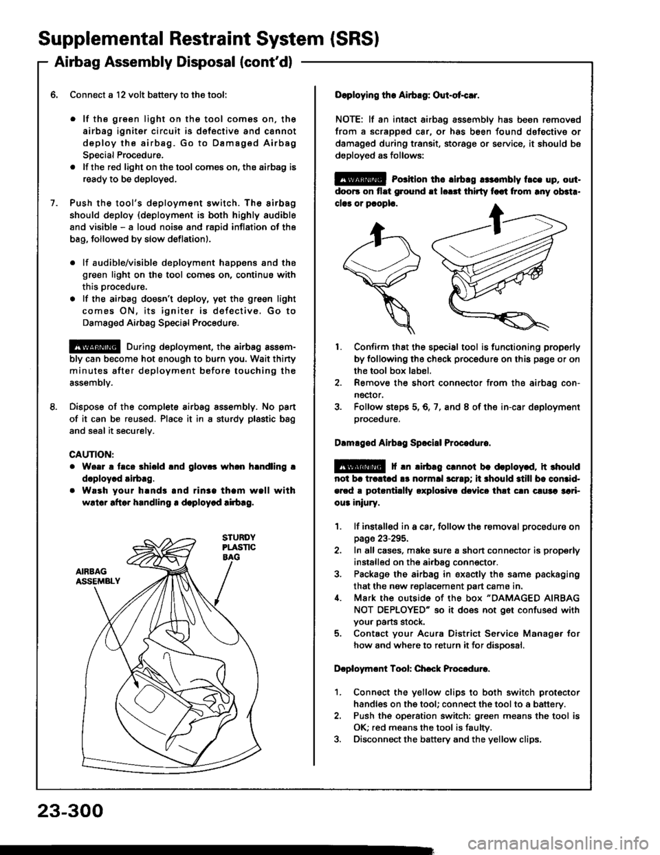
Dispose of the complete airbag sssembly. No pan
of it can be reused. Place it in I sturdy plastic bag
and seal it securelv.
CAUTION:
Woar a taco shiold lnd glov.s whon hlndling !
doploy.d airbag.
Waeh your hands and rin3a tham wall with
wslor aftor handling r deploycd !irb!g.
23-300
Doploying the Airbag: Out-ot{!r.
NOTE: lf an intsct airbag assembly has been removed
from a scrapped car, or has been found dofective or
damagsd during transit, storage or service, it should bs
dsployed as follows:
@ Porition th6 lirbrg rr:.mbly t.ce up, out-
doo6 on flat ground !t lorrt thirty foot from rny ob3t..
clar or pcoplo.
1. Confirm that the special tool is functioning properly
by following the check procedure on this page or on
the tool box label.
2. Remove the short connector from the airbag con-
nector.
3. Folfow steps 5,6,7, and 8 of the in-car deployment
orocequre.
Dlmlged Airbsg Sp.ci8l Procoduro.
E!@ f rn lirbag crnnot be deploy.d, it rhould
not br trcltcd !s normll scrrp; ii 3hould still bc comid-
ercd a potantillly oxplolivr dcvicc thli cln c!u3a 3ari-
ou3 iniury.
1. lf instslled in a car, follow the removal procedure on
page 23-295.
2. In all cases, make sure a short connector is properly
installed on the airbag conn€ctor.
3. Package the airbag in sxacily the same packaging
that the now replacement part cama in.i[. Mark the outside 0f the box "DAMAGED AIRBAG
NOT OEPLOYED" so it does not get confused with
your parts stock.
5. Contact your Acura District Service Manager for
how and where to return it for disoosal.
Dcploymont Tool: Chcck Procedure.
1. Connect the yellow clips to both switch protector
handles on the tool; connect the tool to a battery.
2. Push th€ operation switch: green means the tool is
OK; red means the tool is faulty.
3. Disconnect the battery and the yellow clips.
Page 1406 of 1413
Cable Reel Replacement
!!@ store r rcmov.d rirbrg rsldnbty with thrprd ruf.cc up. It th. .irb.g i3 impropcrly 3to.rd f.ccdown, sccid.ntd d.ploym.rf could propcl th. unit withrnough torca to caure a.?iour iniury.
GAUTION:
o Clrdully in3pcct thc airbrg r$.mbly brtorc instll_ling it. Do not inttrll !n lirb.g |3..mbly ihst fiow3rignr of bring droppcd or improp.rly handled. ruch.3 dant!, crrck3 or dafo?mation.. Atw!$ krro th. tkroR connctot(3l on ths rtbrg \connactor whan tha h|rn!|a l! dbconncstad,. Do lo-t dis.tlambla or tampar with thc ai.brg !r-t.mbly.
NOTE: The original radio has a codod theft Drotoctioncircuit. Bs sure to get the customer,s code numberbsfore disconnecting th6 battery cables.
l. Disconnect th6 banory negstive cable and thsn thepositive cable.
2. Make sure the whe€ls are aligned straight ahoad.
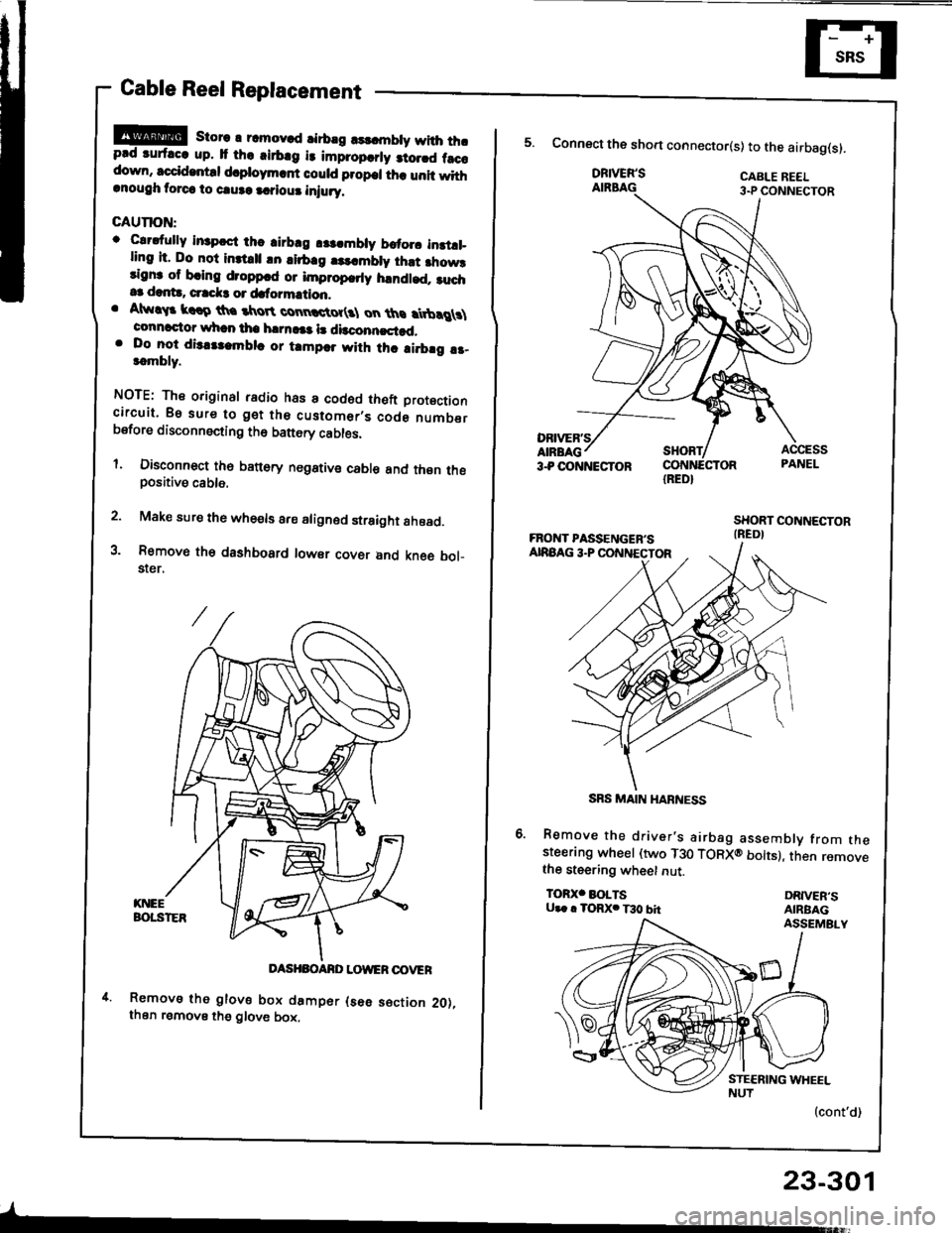
3. Removo th€ dashbosrd lowsr covsr and kne6 bol_$er.
DASHBOANO LOWER OOVER
Removs tho glove box damper (s6e s€ction 2O),then remove the glove box,
-
23-301
IRED}
5. Connect the sho.t connector(s) to the airbag(s).
DRIVER'SAIRBAG
Remove the driver's airbag assembly from thesteerang wheel (two T30 TORXO bolts), then removethe steering wheet nut.
TOR)(' BOLTSU.. . TORX. T30 bhDRIVER'SAIRBAGASSEMBLY
(cont'd)
SRS MAIN HARNESS