Page 519 of 1413
1st-hold Accumulator/Right Side Cover
Disassembly/lnspection/Reassembly
NOTE:
a Clean all pans thoroughly in solvsnt o, carburetor cleaner, and dry with compressed 8ir.
a Blow out all passages.
a coat all parts with ATF betors raassembly.
SNAP RI]TG
l ST.HOLO ACCUMULATOR COVER
1ST-HOLD ACCUMULATOR SPRING
IST.HOLD ACCUMULATOR PISTON
RIGHT SIDE COVER
O.BINGR6place.
SPRING SPECIFICATIONSUnit of length: mm (in)
No.Spring
St8ndard lt{ew)
Wlro Dia.o.D.Froo LengthNo. of Coils
o1 st-hold accumulator spring4.00 (o.1 57)21.50 (0.846)71.70 l2.A23l8.3
14-128
Page 601 of 1413
8.Pack the inboard joint with the ioint grease included
in the new driveshaft set.
Grease quantity; 120 - 130 g 11.2 - 4.6 ozl
9. Fit the inboard joint onto the driveshaft.
NOTE;
. Reinstall the inboard joint onto the driveshaft by
aligning the marks on the inboard ioint and the
rollers.
. Hold the driveshaft so the inboard joint points up
to prevent it from falling off.
Left drivoshaft:Align the holder direction of the rollers
toward the slot ot inboard joint as
INBOARDJOINT
/,.-:--\ \
I sotine di,ection
A\
{(@}
HOLDER
10.Adjust the length of the driveshafts to the figure
below. then adjust the boots to halfway between
full compression and full extension.
NOTE: The ends of boots seat in the groove of the
driveshaft and joint.
Left: 475 - 480 mm {18.7 - 18.9 inl
Right: 475 - 480 mm (18.7 - 18.9 inl
lnstall new boot bands on the boots, and bend both
sets of locking tabs.
Lightly rap on the doubled-over portions to reduce
their height.
{cont'd)
11.
16-9
Page 668 of 1413
60.
Install the new lock washor in the groov€ in the
steering rack.
Hold the steering rack with I wrsnch and tighten
the rack end.
After tightening th€ rack end, stske the four sections
of lock washer with a commercially available roll
Din drift and a mallet.
ROLL PIN DRIFTComm.rcl.lly Av|il.bl.
lsnrp-On No. PPR8 or .rquiv.lenll
NOTE: This drift has a fl8t,
to prevent puncturing
of motal washer.
ol
62.Apply steering groass to the circumferenc6 of tho
rack end housing.
Coat the rack end groove and inside of the boot
with silicone greas€.
lnstsll the boots in ths rack end with the tube
clamos.
NOTE: Install the boots with the rack in the straight
ahsad position (i.6. right and l€ft tis-rods ar€ squal
in length).
(cont'dl
64.
NOTE: Wipe ths gro.se offthe thread s€ction.
TUEE CLAJTIP
17-61
Page 1187 of 1413

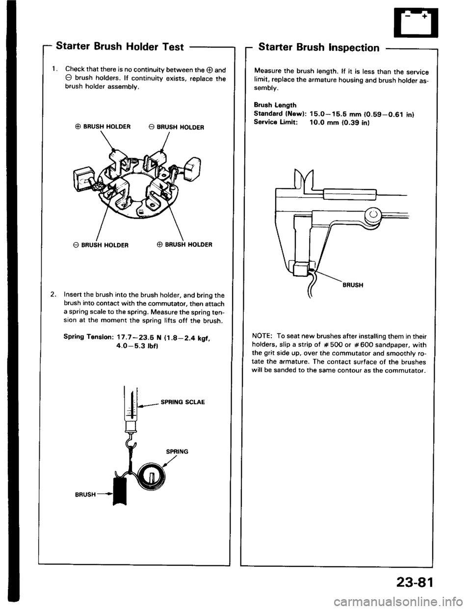
Starter Brush Holder Test
1 . Check that there is no continuity between the O and
O brush holders. lf continuity exists. replace theb,ush holder assembly,
G) BRUSH HOLDER E BRUSH HOLOER
O BRUSH I{OLDERO BRUSH HOLDER
Insert the brush into the brush holder, and bring thebrush into contact with the commutator, then attacha spring scale to the spring, Measure the spring ten-sion at the moment the spring lifts off the brush.
Spring Tension: 17.7 -23.5 N {1.8-2.4 kgf,4.O_5.3 tbfl
SPRING SCLAE
Starter Brush Inspection
Measure the brush length. lf it is less than the servicelimit, replace the armature housing and brush holder as-sembly.
Brush L€ngth
Standard {Now): 15.O- 15.5 mm (0.59-0.61 inlSe.vice Limit: 10.0 mm (0.39 inl
NOTE: To seat new brushes after installing them in their
holders, slip a strip of # 5OO or # 600 sandpaper, with
the grit side up. over the commutator and smoothly ro-
tate the armature. The contact surface of the brushes
will be sanded to the same contour as the commutato..
23-81
Page 1212 of 1413

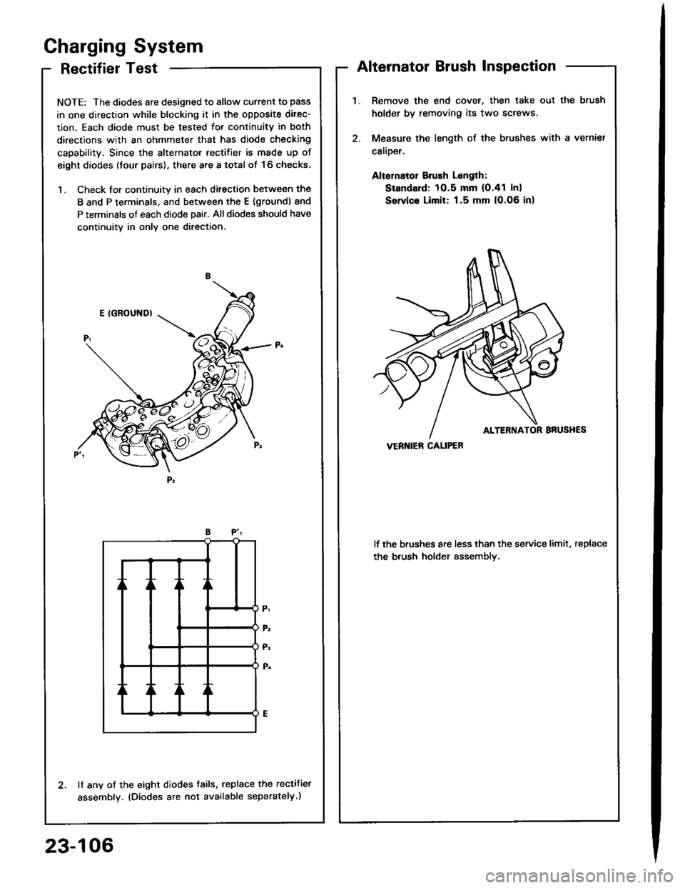
RectifierTest
NOTE: The diodes are designed to allow current to pass
in one direction while blocking it in the opposite direc-
lion. Each diode must be tested for continuitv in both
directions with an ohmmeter that has diode checking
capability. Since the alternator rectifier is made up of
eight diodes (four pairs), there are a total of '16 checks,
1. Check for continuity in each ditection between the
B and P terminals, and between the E (ground) and
P terminals of each diode pair. All diodes should have
continuity in only one direction,
lf any of the eight diodes tails, replace the rectifier
assembly. (Diodes are not available separately.)
Gharging System
Alternator Brush Inspection
Remove the end cover, then lake oul the brush
holder by removing its two screws
Measure the length of the brushes with a vernier
calioer.
Aliornatol Brush Longlh:
Standard: 10.5 mm (O.41 in)
Servic. Limit: 1.5 mm (O.06 in)
lf the brushes are less than the service limit, replace
the b.ush holder assemblv.
VERI{IEB CALIPEB
23-106