Page 491 of 1413

Transmission
Removal
4.Bemove the t.ansmission ground cable from the
transmission hanger.
Disconnect the lock-uD control solenoid valve con-
nector and the shitt control solenoid valve connec-
tor, then remove the harness clamp on the lock-up
control solenoid harness from the harness stav.
a Make sur€ lifts. iacks and safety stands are placad
properly, and hoist brackots are attachod to tho cor-
rect position on ths sngine {seo sectionl }.o Apply parking brake and block rear wheels, so car will
not roll off stands and fall on you whil6 working un-
del it
CAUTION: Use tender covers to avoid damsging paint-
ed surlaces,
1 . Disconnect the battery negative { - } and positive ( + )
cables from the battery.
2. Remove the intake air duct and air cleaner housino
assembly.
HARNESS CLAMP
LOCK-UP CONTROLSOLENOID VALVECONNECTOR
AIR CLEAI{ERHOUSING ASSEMBLY
SHIFT CONTROLSOLENOID VALVECONNECTORTRANSMISSIONGROUND CABI-E
Disconnect the vehicle speed sensor (VSS), main-
shaft sDeed sensor and countershaft speed sensor
connectors.
3.Remove the starter motor cables and cable holder
from the starter motor.VEHICLE SPEEDSENSOR CONNECTOR
STARTER MOTOR CABLECABLE HOLDER
VEHICLE SPEEDSENSOR
COUNTERSHAFTSPEED SENSORCONNECTOR
MAINSHAFT SPEEDSENSORCONNECTOR (cont,d)
STARTER MOTOR?/\
STARTER MOTOR CABLE
4-99
Page 496 of 1413

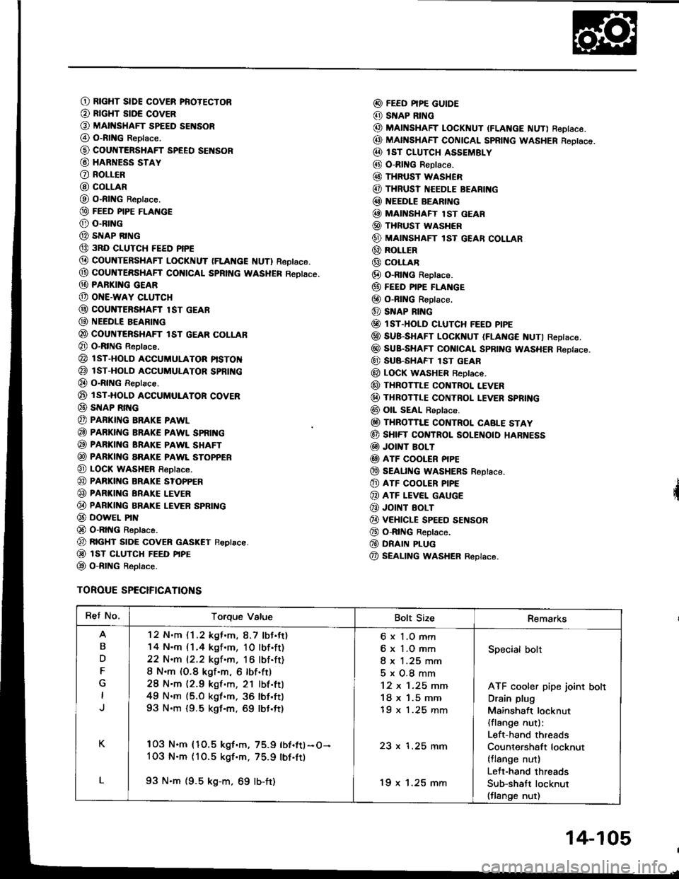
O RtcHT slDE covER pRoTEcToR
@ RrcHT stDE covER
O MAtt{sHAFr spEED sENsoR
@ o-RtNG Reptace.
@ cour{TERSHAFT SPEEO SENSOR
@ HARNESS STAY
O RoLLCR
@ COLLAR
O O-RING Reptace.
@ FEED PIPE FLAI{GE
@ o-RrNG
@ sIrlAP RING
@ 3RD CIUTCH FEED PIPE
@ COUNTERSHAFT LOCKNUT (FLAt{cE f{UTl Reptace.
@ coultTERsHAFf col{tCAL SpRtt{c WASHER Reotace.
@ PARKI G GEAR
@ oNE-waY cLUTcH
@ couNTERsHAFr lsr GEAR
@ NEEDLE BEARING
@ couNTERsHAFr tsr GEAR coLLAB
@ O-RING Reptace.
@ l sT-HoLD accuMuLAToR ptsToN
@ isT-HoLD ACCUMULAToR spBfi{c
@ o-RtNG Reptace.
@ rsT-HoLD ACGUMULAToR covER
@ SNAP Rrr{G
@ PAFKING BRAKE PAWL
@ PARKING BRAKE PAWL SPRII{G
@ PARKING BRAKE PAWL SHAFT
@ PARKING aRAKE PAWL SToPPER
@ LOCK wasHEn Reptace.
@ PARKI G BRAKE s?oPPER
@ PARKING BRAI(E LEVER
@ PARKI G BRAKE LEVER SPBING
@ DowEL PrN
@ O-RltIG Reptace.
@ RTGHT stoE covER GASKET Feptace.
@ isT ct-uTcH FEED ptpE
@ o-RtNG Reptace.
TOROUE SPECIFICATIONS
@ FEED PIPE GUIDE
@ SNAP RING
@ MAINSHAFT LocKNUT {FLANGE NUT) ReDIace.
@ MAfISHAFT CONTCAL SpRtNG WASHER Reotsce.
@ IsT cLUTcH ASSEMBLY
@ O-RING Reptace.
@ THRUST WASHER
@ THRUSI NEEDLE BEARI G
@ EEDLE BEARING
@ MAI'{SHAFT lsT GEAR
@ THRUST WASHER
@ MAINSHAFT lsT GEAR coLLAR
@ RoLLER
@ coLLAR
@ O-Rlt{c Reptace.
@ FEEo PIPE FLANGE
@ o-RING R€ptace.
@ SNAP RING
@ lsr-HoLD cLUTcH FEED ptpE
@ SUB-SHAFT LoCKNUT IFLAt{c€ NUTI Reptace.
@ suB-sHAFr cot{tcAl spRtNG WASHER Reptace.
@ SU8-SHAFT lST GEAR
@ LOCK WASHER f,eptace.
@ THRoTILE cor{TRoL LEVER
@ THRoTTLE coNTRoL I.EVER SPRING
@ oll sEAt Reptace.
@ THRoTTI"E coNTRoL CABLE STAY
@ sHtFT CONTROL SOLEI{O|O HARNESS
@ Jor T BoLT
@ ATF COOLER PIPE
@ SEAL|NG WASHERS Roptace.
@ ATF cooLER P|PE
@ ATF LEVEL GAUGE
@ JOINT EOLT
@ vEHtcLE spEED sEf{soR
@ o-RtNG Reptace.
@ DRAIN PLUG
@ SEALING WASHER Replace.
Ret No.Torque ValueBolt SizeRemarks
B
D
F
K
L
'12 N.m (1 .2 kgf .m, 8.7 lbJ.tt)
14 N.m (1.4 kgf.m, 10lbf.ft)
22 N.m 12.2 kgf.m, 16 lbf.ft)
8 N.m (O.8 kgf.m, 6 lbf.ftl
28 N'm (2.9 kgf .m, 21 lbf.ttl
49 N.m (5.O kgf.m, 36 lbf'ft)
93 N.m {9.5 kgf.m, 69 lbt.ft}
103 N.m {1O.5 kgf.m, 75.9 lbf.ftl-O-
1O3 N.m (10.5 kgf'm. 75.9 lbf.ft)
93 N.m (9.5 kg-m, 69 lb-ft)
6 x 1,O mm
6 x 1.O mm
I x 1.25 mm
5x0.8mm
12 x 1-25 mm
18 x '1.5 mm
tY x t.z5 mm
23 x 1.25 mm
'19 x 1.25 mm
Specialbolt
ATF cooler pipe joint bolt
Drain plug
Mainshaft locknut(flange nut):
Left-hand threads
Countershaft locknut(tlange nut)
Lett-hand threads
Sub-shatt locknut(flange nut)
14-105
Page 557 of 1413

20. Connect the vehicle speed sensor (VSS), mainshatt
speed sensor and counterchalt speed sensor con
nectors.
VEHICLE SPEED SEiISORCONNECTOR
21. Connect the lock-uD control solenoid valve connec-
tor and shift control solenoid valve connector. then
clamp the lock-up control solenoid harness with the
harness stay.
22. Connect the transmission ground cable.
LOCK-UP CONTROLSOLENOID VALVE HARNESS STAY
23. Connect the starter cable to the starter motor, and
install the cable holder.
NOTE: When installing the starter motor cable,
make sure that the crimped side of the ring terminal
is facing out (see section 23).
CABLEHOLDER
6x 1.0 mm'12 N.m (1.2 kgf'm,8.7 lbt.tl)
24.
N.mlO.9 ksr.m, 7 tbr-rtt
STARTER CAELE
Install the air cleaner housing assembly and intake
arr oucl.
AIR CLEANER HOUSINGASSEMBLYINTAKE AIRDUCT
25.
26.
24.
29.
30.
Retill the transmission with ATF(see page '14-93).
Connect the battery positive ( + ) and negative ( - )
cables to the battery.
Start the engine. Set the parking brake, and shift the
transmission through all gears three times.
Check shitr cable adjustment as described on page
14-171 .
Check that front wheel alignment (see section 18).
Let the engine reach operating temperature (the cool-
ing tan comes on) with the transmission in S or @position, then turn it off and check the fluid level.
31. Road test as described on page 14-9o and 91.
14-167
Page 562 of 1413
Gearshift Selector
Disassembly/Reassembly
CAUTION:
a All SRS electrical wiing haln€ssss are covered withy6llow insulation.
a 8€fore disconnecting 8ny pan of the SRS wire har-
neaa. connOct th6 short connectors (sse page 23-701.
a Roplace the entire affected SRS hahess assembly if
il has an opon circuit or damaged wiring.
9.8 N.m {1.O kgf.m, 7.2 lbf.frl
SHIFT LOCK SOLENOID
CONTROL BRACKET
SELECT LEVER BRACKET
CONTROL SEAL
SRS MAIN HARNESS
[E--__ rocK ptN
ADJUSTER
-6{stLtcoNEGREASEe-LEVER COVER
LOCK PIN ROD
-#qSILICONE GREASE
@6
5 N.m (0.5 kgt.m, 4 lbt.ftl
AUTOMATIC TRANSAXLEGEAR POSITION SWITCHTesting, see Section 23
9.8 N.m (1.0
7 .2 tbt.ltl
12 N.m (1.2 kgf.m, 8.7 lbf.ftl
9.8 N.m 11.0 kgf'm,7.2 lbf.ftl
14-172
Page 563 of 1413
Shift Indicator Panel
Adjustmet
CAUTION:
a All SRS olectrical wifng harnesses aro covered withyellow insulation.
a Bofors disconnecting any pan of the SRS wire har-
ness, connect tho sho.t connectors {sse page 23-7O),
a Replace the entire aflect€d SRS harness assembly if
it has an open circuit or damaged wiring,
1.Check that the index mark on the indicator aligns
with the N]mark on the shift indicator panel when
the transmission in NEUTRAL.
lf not aligned, remove the center console (see sec-
tion 2O).
Remove the shift indicator panel mountinq screws
and adjust by moving the panel.
NOTE: Whenever the shift indicator panel is re-
moved, reinstall the panel as described above.
MOUNTING SCREW3 N'm lO.3 kst.m, 2 lbf.ftt
INDEX MARK
@
@
@
SRS MAIN HARNESS
14-173
Page 635 of 1413
Steering Golumn
Removal
LOWER COVER
Remove the column covers
screws.
CAUTION:
. All SRS el€ctrical wiring hlrnesses are coversd withyollow insuhtion.
. Bctore dieconnocting any part ol tho SRS wiro h!r-
nesa, connoct the thort connector (s).
. Roplace tho ontire aftected SRS harness asr€mbly if
it has !n open circuit or d!mlgod wiring.
Remove the airbag assembly and steering wheel
.(see page 17-25).
Remove the lower cover.
Remove the driver's knee bolster.
by re mov in g the
17-2A
scREws
5. Remove the connector holder and disconnect the
SRS main harness from the cable reel wire ha.ness
at the under side ot the column bracket.
HARNESS
Remove the cable reel and turn signal canceling
steeve.
Remove the combination switch from the steering
column by disconnecting the connectors,
TURN SIGNAL CANCELINGSlTEVE
COMA|NANON SW]TCH
7.
CABI..E REEL
STEERING COLUMN
Page 640 of 1413
7.
Connect the ignition switch wire connectors to the
under-dash fuse/relav box.
Install the combination switch and turn signal can-
celing sleeve onto the steering column.
NOTE: Be sure the wires are not caught or pinched
by any parts when installing the combination
switch.
TURN SIGNAL CANCELINGSLEEVE
Install the cable reel onto the steering column, then
connect the SRS main harness and cable reel wiro
harness and install the connector holder.
NOTE: Align the slot in the cable reel with the pro-
jection on the canceling sleeve.
coMatNATroN swncH
UPPER COLUMN COVER
9. Installthe column covers.
scREws
lnstall the driver's knee bolster.
lnstall the lower cover.
Installthe steering wheel {see page '17-26).
10.
11.
't2.
17-33
Page 1005 of 1413

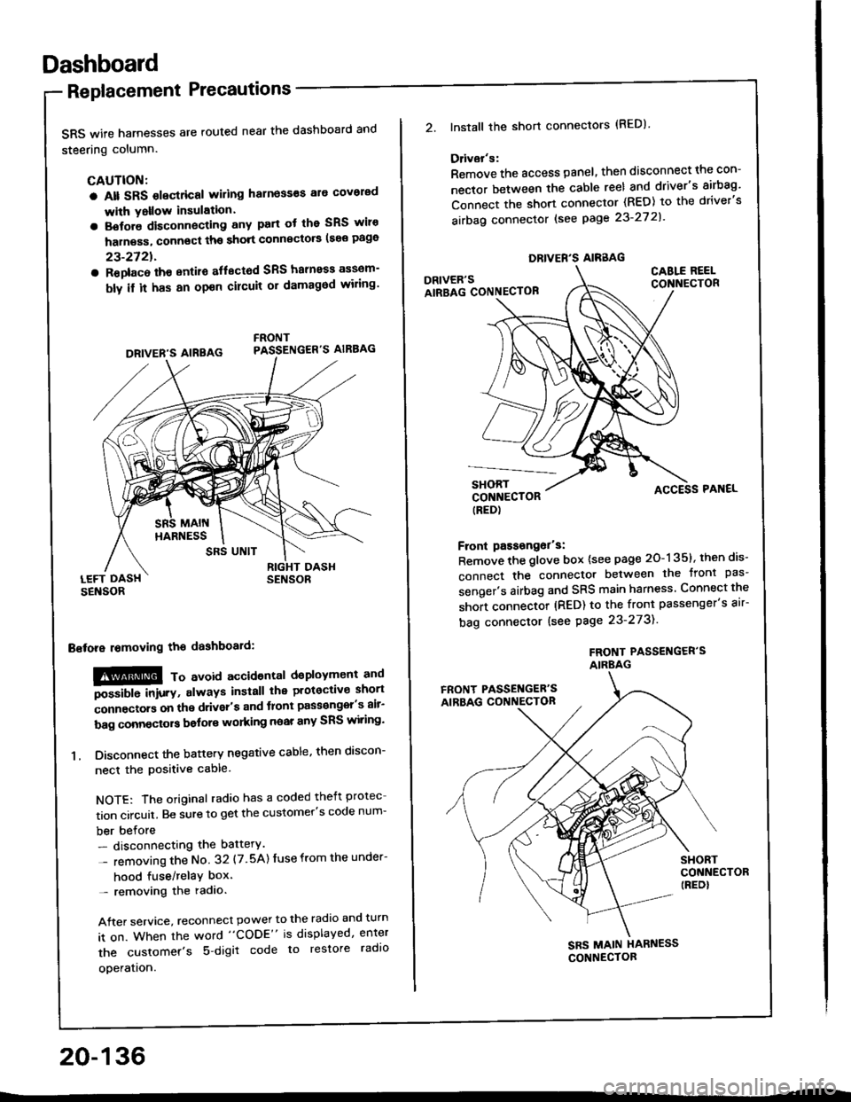
Dashboard
Replacement Precautions
SRS wife harnesses are routed near the dashboard and
steering column.
CAUTION:
a Alt SRS olectrical wiling harness€s ale covorad
with Yollow insulation.
a Botore disconnecting any part ot the SRS wiro
harness, connect ths short connscto6 (see page
23-2721.
a Roplac6 ih€ entiro aflectod SRS halnoss assem-
bly il it has an opon cilcuit or damagod wiling'
LEFT DASHSENSOR
Bstora lomoving the dashboaid:
!@@ To avord accioenlal dsployment and
""iUU inir.v, always install the plotoctive short
;onnectors on the driver's and tlont pass€ngel's air-
bag connectors bolors working near any SRS wiring'
1. Disconnect the battery negative cable, then discon-
necl the positive cable.
NOTE: The original radio has a coded theft protec
tion circuit. Be sure to get the customer's code num-
ber before- disconnecting the battery.
- removing the No 32 (7.5A) Iuse from the under-
hood fuse/relaY box'- removing the radio.
After service, reconnect power to the radio and turn
it on. When the word "CODE" is displayed, enter
the customer's 5 digit code to restore radlo
ooeration.
DRIVER'S AIREAG
SRS UNIT
20-136
DRIVER'S AIRBAG
2.lnstall the short connectors (RED)
Ddvar's:
Remove the access panel, then disconnect the con-
nector between the cable reel and driver's airbag'
Connect the short connector (RED) to the driver's
airbag connector lsee page 23-27 2l'
DRIVER'SAIRBAG CONNECTOB
CABLE REELCONNECTOR
SHORTCONNECTOR(RED)
Front passongor's:
Remove the glove box {see page 20-135}, then dis-
connect the connector between the tront pas'
senger's airbag and SRS main harness Connect the
short connector (RED) to the front passenger's air-
bag connector (see Page 23-273).
FROf{T PASSENGER'SAIRBAG
ACCESS PAI{EL
FRONT PASSET{GER'SAIRBAG CONNECTON
SHORTCONNECTOR(REDI
SBS MAIN HARNESS
CONNECTOR