Page 672 of 1413

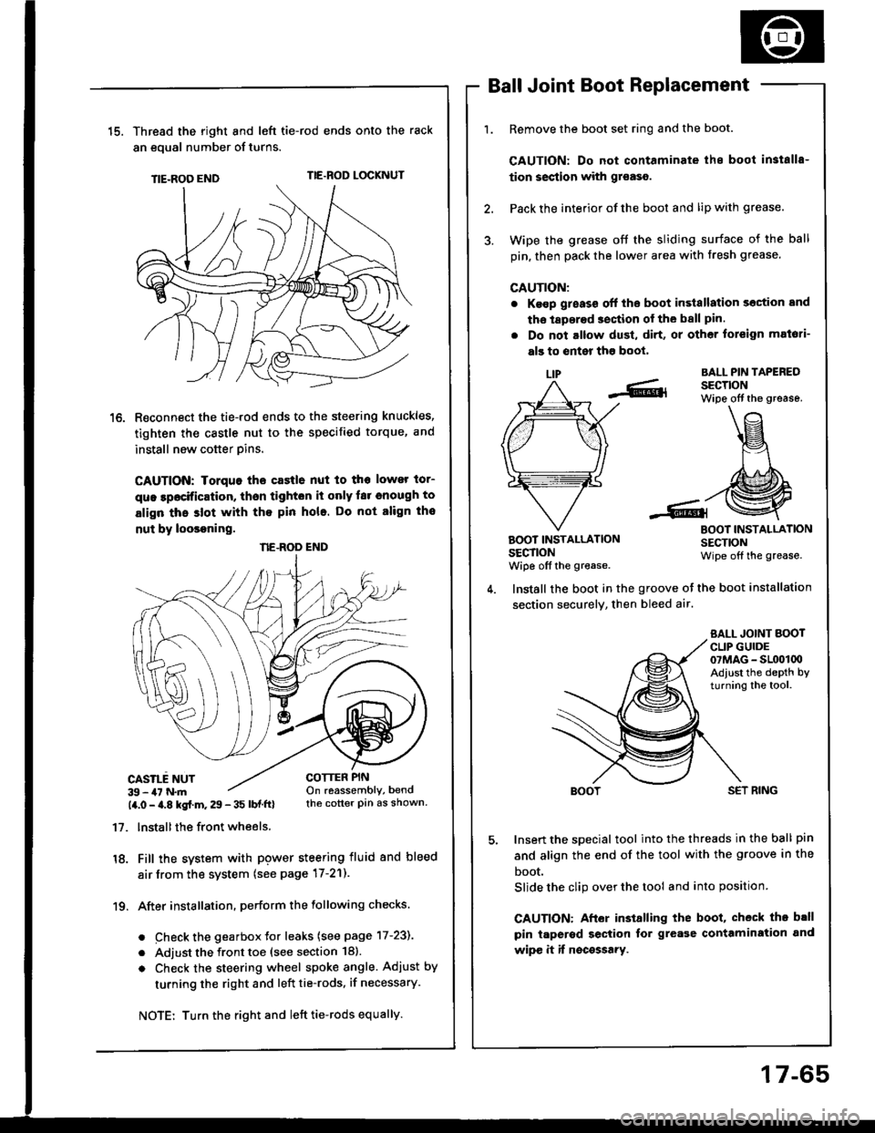
15.Thread the right and lefi tie-rod ends onto the rack
an eoual number of turns.
TIE-ROO ENDTIE.ROD LOCKNUT
R€connect the tie-rod ends to the steering knuckles,
tighten the castle nut to the specified torque, and
install new cotter pins.
CAUTION: Iorquo tho castle nut to tho lower tor-
que lpocification, thsn tighton it only far cnough to
align thc slot with tho pin hole. Do not align tho
nut by loosoning.
CASILE NUT39 - 47 N.m14.0 - a.8 kgf.m. 29 - 35 lbf ftl
17. lnstallthe front wheels.
18. Fill the system with pgwer steering fluid and bleed
air from the system (see page 17-21).
19. After installation. perform the following checks.
. Check the gearbox Jor leaks (see page 17-231
. Adjust the front toe (see section 18).
o Check the steering wheel spoke angle. Adjust by
turning the right and left tie-rods, if necessary.
Ball Joint Boot Replacement
Remove the boot set ring and the boot.
CAUTION: Do not contaminate ihe boot in3talls-
tion section with gr€aso.
Pack the interior of the boot and lip with grease.
Wipe the grease off the sliding surface of the ball
pin, then pack the lower area with fresh grease.
CAUTION:
. Ke€p g;eass off the boot in3tallation section and
tho laperad section of the ball pin.
. Do not altow dust, di.t, or other toreign mat6ti-
als to enter tho boot,
LIPBALL PIN TAPEREDSECTIONWipe off the grease.
BOOT INSTALLATIONSECTIONwiDe off the grease.
BOOT INSTALLATIONSECTIONWipe off the grease.
COTTER PINOn reassembly, bendthe cotter pin as shown.
Install the boot in the groove ot the boot installation
section securely, then bleed air.
SALL JOINT BOOTCLIP GUIDE07MAG - SL(x)l00Adiust the depth byturning the tool.
SET RING
Insert the special tool into the threads in the ball pin
and align the end of the tool with the groove in the
boot.
Slide the clip over the tool and into position
CAUTION: After installing the boot, check th. b.ll
pin taperod section tor grease contamiration and
wipe it if nocossary.
NE.ROD END
Turn the right and left tie-rods equally.
17-65
Page 1028 of 1413
Hatch Spoiler
Replacement
a Take care not to scratch the hatch.a Open the hatch.
1. Remove the hatch side trim and hatch trim panel (seepage 2O-146).
2. Remove the nuts and disconnect the connector.
: Nut locations, 4
6 x 1.0 mm
Ch 9.8 N.m(J (1.0 ksl m, I__. 7,4b1!t ,/coI{t{EcroR
Remove the hatch spoiler by turning the clip nut onthe left side counterclockwise.
HATCH SPOILER
3. Installation is the reverse of the removal procedure.
Fender Well Trim and
Wheelhouse Protector
Replacement
a Take care not to bend the tender well trim.a Before installing the lender well trim, clean the bodvbonding surface with a sponge dampened in alcohol.a After cleaning, keep oil, g.ease or wafer lrom getlingon the surface.
> i Scr€w locations.
I
ADHESIVEFENDER WELLTRIM
20-159
Page 1178 of 1413

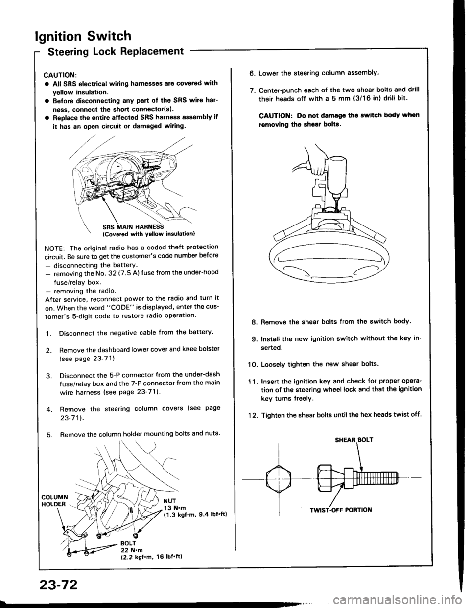
lgnition Switch
Steering Lock Replacement
CAUTION:
a All SRS electrical wiring harnesses ale covsred with
yellow insulation.
a Belore disconnecting any parl ot the SRS wir€ hal-
ness, connecl the short connector{s).
a Replace the entire alfected SRS harness a$6mbly il
it has an open circuit or damaged wiring.
NOTE: The original radio has a coded thett protection
circuit. Be sure to get the customer's code number betore
- disconnecting the batterY.
- removing the No. 32 (7.5 A) fuse from the under-hood
fuse/relay box.- removing the radio.
After service, reconnect power to the radio and turn it
on. When the word "CODE" is displayed, enter the cus-
tomer's 5-digit code to restore radio operation.
1. Disconnect the negative cable from the battery.
2. Remove the dashboald lower cover and knee bolster
(see page 23-7'l ).
3. Disconnect the 5-P connector from the under-dash
fuse/relay box and the 7-P connector trom the main
wire harness {see page 23-71).
4. Remove the steering column covers (see page
23-711.
5. Remove the column holder mounting bolts and nuts'
BOLT22 N.m
12.2 kgl'm.
NUT13 N.m(1.3 kgf.m, 9.4 lbl'ftl
23-72
16 tbt.ftl
6. Lower the steering column sssembly.
7. Center-Dunch each oJ the two shear bolts and drill
their heads off with a 5 mm {3/1 6 in) drill bit'
CAUTION: Do not dama96 tho switch body whon
r€movlng the shoar bol$.
Remove the shear bolts from the switch body.
Install the new ignition switch without the key in-
serted.
Loosely tighten the new shear bolts.
Insert the ignition key and check for proper opera-
tion of the steering wheel lock and that th€ ignition
key turns freely.
Tighten the shear bolts untilthe hex heads twist off.
8.
q
10.
11.
12.
Page 1402 of 1413
CAUTION: Bo 3uro to in3tsll tho SRS wiring so that it isnot pinchod or intoforing with other car parts.
4. Install the new airbag(s):
Driver's Sido: Place the driver's airbag assembly inthe steering wheel, and secure it with new TORX@bolts.
TORXC BOLT9.8 N'm 11.0 kgt m.7.2lbf.ftl Replace.Uio a TORXO T30 bit
TORXO BOLI9,8 N'm l'1.0 kgf.m,7.2lbtftl Replaco.Us. . TORX6 T30 bit
Front Pa$aogsr's Sid€:
. Place the front passenger's airbag assembly in thedashboard.
Loosely install all four mounting nuts.
Tighten the upper two nuts first, then the lowsr twonuts. Adjust the lower mounting bracket if necessarV.
FRONT PASSENGER'SAIRBAGASSEMALY
UPPERMOUNTING NUTS
LOWERMOUNTING NUTS9.8 N.m (1.0lgtm, t.2lbtftlReolace.
CONNECTORIREDI
{cont'd)
23-297
Page 1406 of 1413

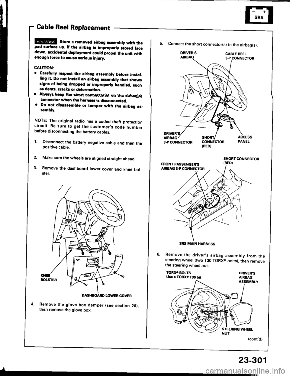
Cable Reel Replacement
!!@ store r rcmov.d rirbrg rsldnbty with thrprd ruf.cc up. It th. .irb.g i3 impropcrly 3to.rd f.ccdown, sccid.ntd d.ploym.rf could propcl th. unit withrnough torca to caure a.?iour iniury.
GAUTION:
o Clrdully in3pcct thc airbrg r$.mbly brtorc instll_ling it. Do not inttrll !n lirb.g |3..mbly ihst fiow3rignr of bring droppcd or improp.rly handled. ruch.3 dant!, crrck3 or dafo?mation.. Atw!$ krro th. tkroR connctot(3l on ths rtbrg \connactor whan tha h|rn!|a l! dbconncstad,. Do lo-t dis.tlambla or tampar with thc ai.brg !r-t.mbly.
NOTE: The original radio has a codod theft Drotoctioncircuit. Bs sure to get the customer,s code numberbsfore disconnecting th6 battery cables.
l. Disconnect th6 banory negstive cable and thsn thepositive cable.
2. Make sure the whe€ls are aligned straight ahoad.
3. Removo th€ dashbosrd lowsr covsr and kne6 bol_$er.
DASHBOANO LOWER OOVER
Removs tho glove box damper (s6e s€ction 2O),then remove the glove box,
-
23-301
IRED}
5. Connect the sho.t connector(s) to the airbag(s).
DRIVER'SAIRBAG
Remove the driver's airbag assembly from thesteerang wheel (two T30 TORXO bolts), then removethe steering wheet nut.
TOR)(' BOLTSU.. . TORX. T30 bhDRIVER'SAIRBAGASSEMBLY
(cont'd)
SRS MAIN HARNESS
Page 1409 of 1413

Supplemental Restraint System {SRSI
Cable Reel Replacement (cont'd)
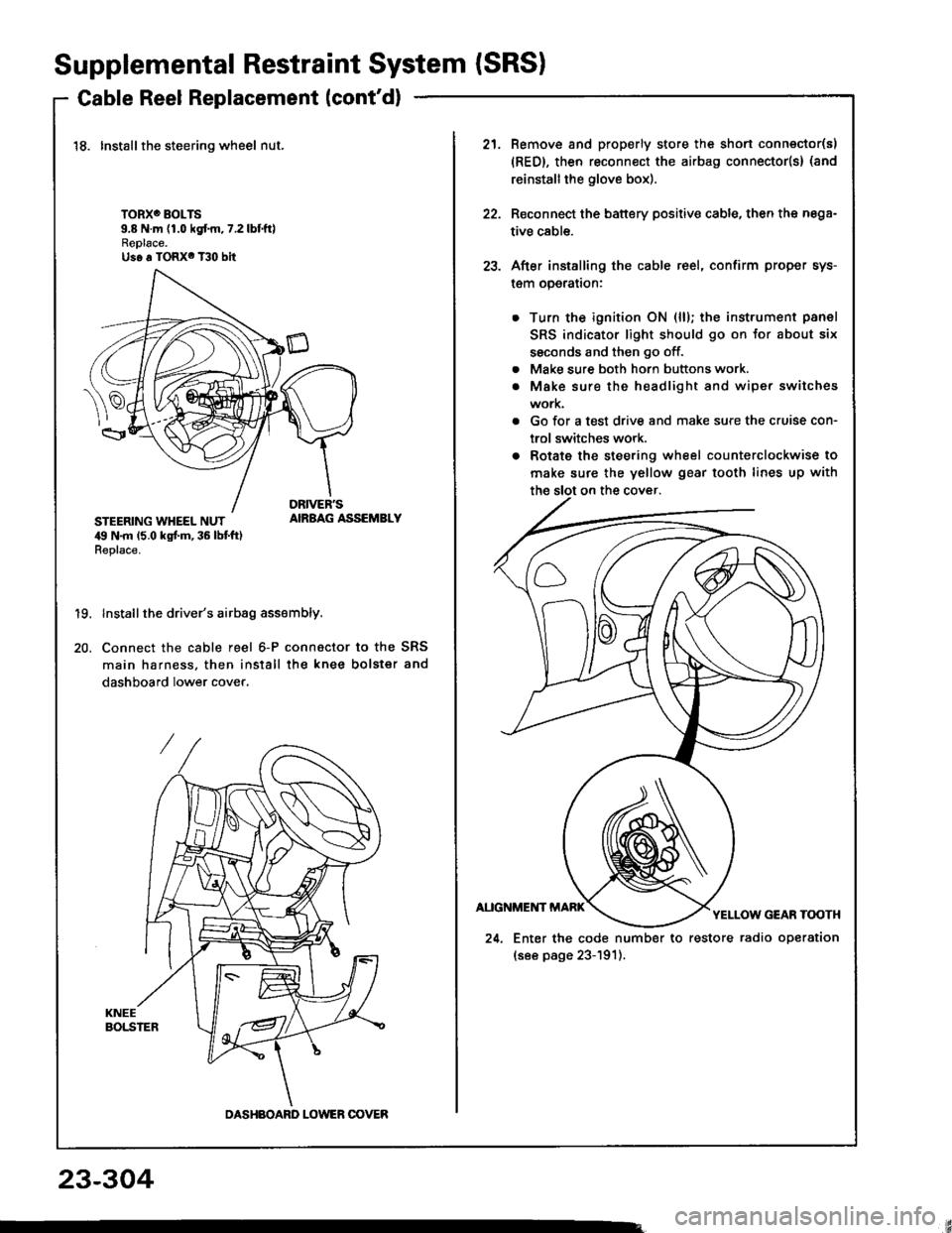
18. Installthe steering wheel nut.
TORXO BOLTS9.8 N.m (1.0 kgf.m,7.2lbtftlReplace.Us6 a TORX6 T30 bit
STEERING WHEEL NUT,19 N.m 15.0 kgt m, 36 lbt ft)Replace.
AIRBAG ASSEMBLY
19.
20.
Install the driver's airbag assembly.
Connect the cable reel 6-P connactor to the SRS
main harness, then install the knee bolster and
dashboard lower cover.
DASHBOARD LOWER OOVER
21.Remove and properly store the shon connector(s)
{RED}, then reconnect the airbag connector(s} (and
reinstall the glove box).
Reconnect the battery positive cable, then the nega-
tive cable.
After installing the cable reel, confirm proper sys-
l€m operalron:
Turn the ignition ON (ll); the instrument panel
SRS indicator light should go on for about six
ssconds and then go off.
Make sure both horn buttons work.
Make sure the headlight and wiper switches
work.
Go for a test drive and make sure the cruise con-
trol switches work.
Rotate the steering wheel counterclockwise to
make sure the yellow gear tooth lines up with
22.
23.
a
a
24. Enter the code number to restore radio operation
(see page 23-191).
23-304
Page:
< prev 1-8 9-16 17-24