Page 670 of 1413

lnstallation
CAUTION; BG Glrc{ul not io bcnd or drm8go tho piping
whcn in3tllling tho gea.box.
1. Before installing the gearbox, slide the rack all the
way to right.
2. Pass the right side of the steering gearbox above
and through the right side of the rear beam.
3. Hold the steering gearbox and slide the rack all the
wav to the left.
4. Raise the left side of the steering gearbox above
and through the left side of the rear beam.
5. Install the pinion shaft grommet and insert the pin-
ion shaft up through the bulkhead.
NOTE: Align the tab on the pinion shaft grommet
with the slot in the valve bodv.
6. Install and tighten the gearbox mounting bolts.
NOTE: After installing the gearbox, check the air
hose connactions for interference with adjacent
pans.
58 N.m 15.9 kg[.m, $ lbl.ftl
TAA
38 N m 13.9 kgl.m, 28 lbt.ftl
17-63
YELLOW GEAR TOOTH
7.Center the steering rack within its stroke.
Make sure that the cable reel of the SRS is centered
as follows:
. Turn the steering wheel left approx. 150 degrees,
to check the cable reel position with indicator.
. lfthe cable reel is centered. the yellow gear tooth
lines up with the alignment mark on the cover.
. Return the steering wheel right approx. 150
degrees to position the steering wheel in the
straight ahead position.
ALIGNMEi'IT MARK
Slip the lower end of the steering joint onto the pin-
ion shaft (line up the bolt hole with the groove
around the shaft), and tighten the lower bolt.
NOTE:
. Connect the steering shaft and pinion with the
cable reel and steering rack centered.
. Be sure that the lower steering ioint bolt is se-
curely in the groove in the steering gearbox pin-
ion.
. lf the steering wheel and rack are not centeted,
reposition the serralions at lower end of the
steering joint.
(cont'dl
22 N.m 12.2 kgi.m, 16lbf.ftlLOWER BOLT
Page 948 of 1413

Rear Edge Closing Adjustment
Open the glass about a foot, then close it to check where
rear edge begins to rise. lf it rises too soon and seats too
tightly against the roof panel, or too late and does not
seat tightly enough, adjust it.
1. Remove the headliner (see psge 20-98).
2. Remove the glass.
3. Remove the motor {see page 2O-8O).
4. Align the tilt-up position of the lifter on each side.
Check that the alignment left and right. then install
the motor.
Install the glass, then check for water leaks.
NOTE: Do not use high pressure wate..
lnstall the headliner.
Glass and Sunshade Redacernent
1. Open the sunshade.
2. Tilt-up the glass.
3. Remove the bolts, then remove the glass from rheglass bracket.
V : 8oh locations, 6
4. Remove the screw and lift the sunshade rail on each
side.
5. Silde the sunshade
sunshade.
V : Scraw locations, 2
forwa.d, then remove the
SUNSI{ADE
l-tII
)
6
7
Installation is the reverse of the removal procedure.
Check for water leaks.
NOTE: Do not use high pressure water.
GLASS BRACKET
20-79
Page 949 of 1413

Moonroof
Motor, Drain Tube and Frame Replacement
CAUTION: B€ caretul not to damag€ lhe seats, dash-
board and other interior trim.
1. Remove the glass (see page 2O-79) and headliner
(see page 20-98).
2. Disconnect the motor connector, and remove the
clips securing the ceiling light wire harness.
3. Remove the bolts and nuts, then remove the motor,
if necessarv,
NOTE: Make sure both sliders are parallel when in-
stalling the motor.
: 8olt, nut locationg
A
: Bolt, 2
6x1.Omm I9.8 N.m ILd tt.o kgf.-, I,.?- ", _,/
< : CliD locations. 2
CEILIING LIGHT
FRAME
B : Nut, 3
20-80
4.Disconnect the drain tubes.
Remove the bolts, then remove the trame from the
car.
NOTE: You may require assistance when removing
the frame.
: Eolt locations, I
6 x 1.0 mm
DRAIN TUBETo install, slide the draintube over the ftame nozzleat least 10 mm {O.4 in}.
6.
TUBE CI-IP
Pull the drain tubes out the front and rear pillars.
NOTE; Betore pulling out the drain tube, tie a string
to the end of it so it can be reinstalled.
Installation is the reverse ol the removal procedure.
NOTE:
a Clean the surtace of the frame.
a Check the trame seal.
a Check for water leaks.
7.
9.8 N.m (1.0 kgt m,7.2 rbr.ttl )
FRAME
FRONT
Page 955 of 1413

Moonroof
Rear Edge Closing Adjustment
Open the glass about a foot, then close it to check where
rear edge begins to rise. It it rises too soon and seats too
tightly against the roof panel, or too late and does not
seat tightly enough, adjust it.
1. Remove the headliner (see page 20-1OO).
2. Remove the glass.
3. Remove the motor (see page 20-87).
4. Align the tilt-up position of the lifter on each side.
o.
5.
7.
Check that the alignment lett and right, then install
the motor.
Install the glass. then check for water leaks.
NOTE: Do not use high pressure water.
Install the headliner.
Glass and Sunshade Replacement
1. Open the sunshade.
2. Tilt-up the glass.
3, Remove the bolts, then remove the glass from the
glass bracket.
Using the moonroof
BOLTS6 x 1.O mm9.8 N'm lt O kgf m,
4.
5.
7.2 tbt.ftl
Remove the screws and lift the sunshade rails.
Silde the sunshade forward. then remove the
sunsnaoe.
SUlTSHADERAIL
Installation is the.everse ot the removal procedure.
Check for water leaks.
NOTE: Do not use high pressure water.
GLASS BRACKET
20-86
Page 956 of 1413

Motor, Drain Tube and Frame Replacement
CAUTION: Be carotul not to damago th€ seats, dash-
board and other int6rior trim,
1. Remove the glass (see page 2O-86) and headliner(see page 20-10O).
Disconnect the motor connector, and remove the
clips securing the ceiling light wire harness.
NOTE: To remove the motor, remove the screws.
Disconnect the drain tubes.
Loosen the front bolts.
Remove the bolts, then remove the trame from the
car.
NOTE:
a You may require assistance when removing the
trame.
a Take care not to bend the sunshade rails.
TUBECLIP
DRAIN TUBETo install, slade the drain tube ov6rthe frame nozzle at least 10 mm lO.4 in).
SUNSHADERAILS
Pullthe drain tubes out of the tront and rear oillars.
NOTE: Before pulling out the drain tube, tie a string
to the end of it so it can be reinstalled.
Installation is the reverse of the removal grocedure.
NOTE:
a Install the tube clips with the ends facing the side to easea Clean the surtace of the frame.
a Check the frame seal.
a Check for water leaks.
a Make sure the sunshade moves smoothlv.
SCREW
4.
\/
Make sure the sliders areparallel when installing themotor,
CONNECTOR
FRAME
BOLT6 x 1.0 mm9.8 N.m (1.O lg{.rn.7.2 tbt.ttl
Loosen the tront bohs
Fo?w!?d
tt.
FRONTDRAIN VALVES
installation of the headliner.
20-87
Page 968 of 1413
Remove the grab handle (front passenger.s) and grabhole caps (driver's),
: Scrow locations l2l
5. Remove the socket plug (moonroof model).
4.
FRAME
//Gr-@'
I
n{ +=s ,
SOCKETPLUG
HOOKS
_t :
e)
Remove the roof trim (moonroot model).Open the hatch, then remove the rear root trim.Remove the headliner.
ROOF TRIMsocxET
HEADLII{ER
(cont'dl
6. Remove the upper anchor bolts from the front andrear seat belts (see pages 2O-l j 5, I l9).
7. Remove the upper ponion of the quaner pilla. trimpanel, then detach the headliner clio on each side.
A : Clip locotions, 2
8.
HEADLINER
OUARTER PILLARTRIM PANEL
20-99
Page 1016 of 1413

8.
o.
7.
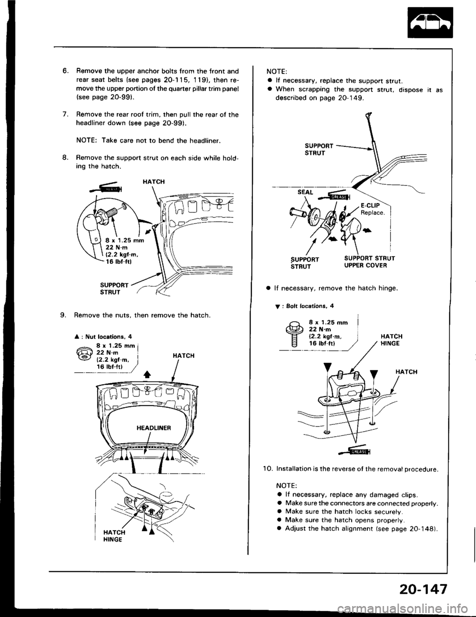
9. Remove the nuts, then remove the hatch.
a : Nut locations, 4
Remove the uDDer anchor bolts from the tront and
rear seat belts {see pages 20-1 1 5, 'l 19), then re-
move the upper portion of the quarter pillar trim panel
(see page 20-991.
Remove the rear roof trim, then pull the rear of the
headliner down (see page 2O-99).
NOTE: Take care not to bend the headliner,
Remove the support stfut on each side while hold-
ing the hatch.
SUPPORTSTRUT
HATCH
HATCH
I x 1.25 mm22Nm
12,2 kgt'm,16 tbt.ftl
12.2 kgl.m, I,6'y!:t ,/
NOTE:
a lf necessary, replace the support strut.a When scrapping the suppon $rut, dispose ir as
described on page 20-149.
a lf necessary, remove the hatch hinge.
V : Solt locdlions, 4
8 x 1.25 mm22 N.rn12.2 kgt.m,16 tbf.ft)HATCHHINGE
HATCH
1O. Installation is the reverse ot the removal procedure.
NOTE:
a lf necessary, replace any damaged clips.a Make sure the connectors are connected properly.
a Make sure the hatch locks securely.a Make sure the hatch opens properly.
a Adjust the hatch alignment (see page 20-148).
20-147
Page 1178 of 1413

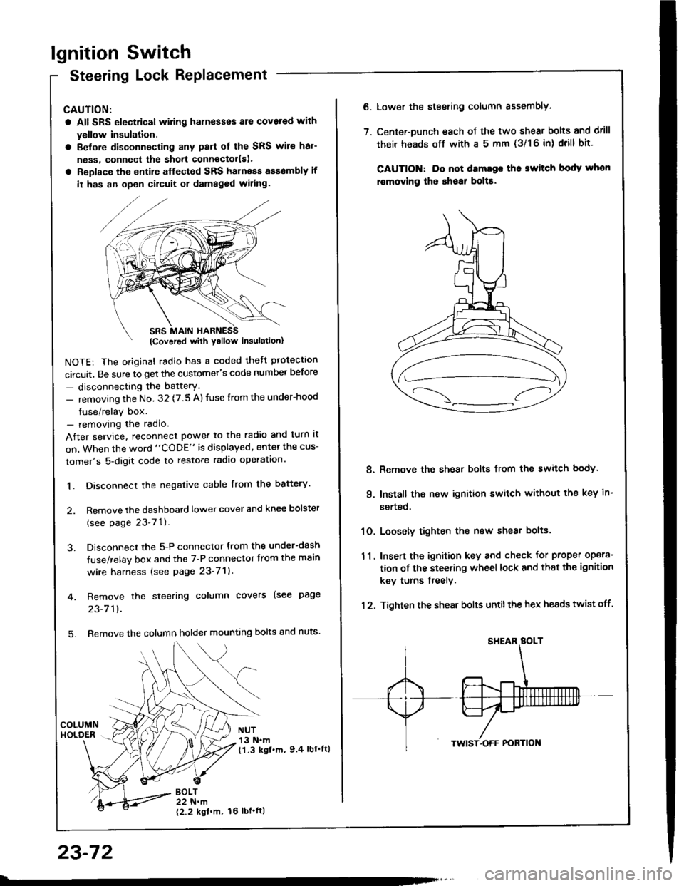
lgnition Switch
Steering Lock Replacement
CAUTION:
a All SRS electrical wiring harnesses ale covsred with
yellow insulation.
a Belore disconnecting any parl ot the SRS wir€ hal-
ness, connecl the short connector{s).
a Replace the entire alfected SRS harness a$6mbly il
it has an open circuit or damaged wiring.
NOTE: The original radio has a coded thett protection
circuit. Be sure to get the customer's code number betore
- disconnecting the batterY.
- removing the No. 32 (7.5 A) fuse from the under-hood
fuse/relay box.- removing the radio.
After service, reconnect power to the radio and turn it
on. When the word "CODE" is displayed, enter the cus-
tomer's 5-digit code to restore radio operation.
1. Disconnect the negative cable from the battery.
2. Remove the dashboald lower cover and knee bolster
(see page 23-7'l ).
3. Disconnect the 5-P connector from the under-dash
fuse/relay box and the 7-P connector trom the main
wire harness {see page 23-71).
4. Remove the steering column covers (see page
23-711.
5. Remove the column holder mounting bolts and nuts'
BOLT22 N.m
12.2 kgl'm.
NUT13 N.m(1.3 kgf.m, 9.4 lbl'ftl
23-72
16 tbt.ftl
6. Lower the steering column sssembly.
7. Center-Dunch each oJ the two shear bolts and drill
their heads off with a 5 mm {3/1 6 in) drill bit'
CAUTION: Do not dama96 tho switch body whon
r€movlng the shoar bol$.
Remove the shear bolts from the switch body.
Install the new ignition switch without the key in-
serted.
Loosely tighten the new shear bolts.
Insert the ignition key and check for proper opera-
tion of the steering wheel lock and that th€ ignition
key turns freely.
Tighten the shear bolts untilthe hex heads twist off.
8.
q
10.
11.
12.