Page 156 of 1413
Piston
lnstallation
'1.
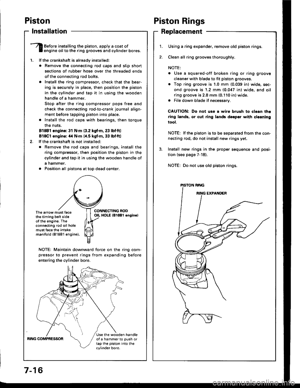
Before installing the piston, apply a coat ofengine oil to the ring grooves and cylinder bores.
lf the crankshaft is already installed:
. Remove the connecting rod caps and slip short
sections of rubber hose ove. the threaded ends
of the connecting rod bolts.
a Install the ring compressor, check that the bear'
ing is securely in place, then position the piston
in the cylinder and tap it in using the wooden
handle of a hammer.
Stop after the ring compressor pops free and
check the connecting rod-to-crank journal align-
ment before tapping piston into place.
. Install the rod caps with bearings, then torque
the nuts,
81881 ongino: 31 N.m {3.2 kgf.m, 23 lbf.ftl
818C1 cngino: 44 N'm 1,t.5 kgf.m, 33 lbf.ftl
lf the crankshaft is not installed:
o Remove the rod caps and bearings. install the
ring compressor, then position the piston in the
cylinder and tap it in using the wooden handle of
a nammer.
. Position all Distons at toD dead center.
CONNECTING RODOIL HOI-E (Br8Bl onginelThe arrow must facethe timing belt sideof the engine. Theconnecting rod oil holemust lace the intak€manifold {81881 €ngine).
NOTE: Maintain downward force on the ring com-
pressor to prevent rings from expanding before
entering the cylinder bore,
BING COMPRESSORUse the wooden handleof a hammer to push ortap the piston into thecylinder bore.
Piston Rings
Replacement
1.Using a ring expander, remove old piston rings.
Clean all ring g.ooves thoroughly.
NOTE:
. Use a squared-oJf broken ring or ring groove
cleaner with blade to fit piston grooves.
. Top ring groove is 1.0 mm (0.039 in) wide, sec-
ond groove is 1.2 mm (0.047 in) wide. and oil
ring groove is 2.8 mm (0.110 in) wide.. File down blade if necessary.
CAUTION: Do not use a wire brush to cloan thr
ring lands, or cut ring lands dsopo. with cl€aning
tool.
NOTE: lf the piston is to be separated from the con-
necting rod, do not install new rings yet.
Install new rings in the prope. sequence and posi-
tion (see page 7-18).
NOTE: Do not use old piston rings.
Page 162 of 1413
Connecting Rods
Selection
Each rod falls into one of four tolerance ranges (from 0
to + 0.024 mm (0 to + 0.0009 inl, in 0.006 mm {0.0002 in)
increments) depending on the size ot its big end bore.
It's then stamped with a number (1,2,3, or 4) indicating
the range.
You may find any combination ol 1, 2, 3, or 4 in any
engane.
Normsl Boro Sizoi ,18.0 mm 11.89 inl
NOTE:
a Reference numbers are Jor big end bore size and do
NOT indicate the position of the rod in the engine.
. Inspect connecting rod for cracks and heat damage.
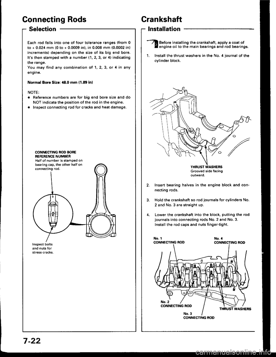
CONNECNNG ROD BOREREFERENCE NUMBERHalf oI number is stamped onbearing cap. th€ other halfonconnecting rod.
Crankshaft
lnstallation
Before installing the crankshaft. apply a coat ofengine oil to the main bearings and rod bearings.
1. Install the thrust washers in the No. 4 iournsl of the
cvlinder block.
Grooved side tacingo!tward
Insert bearing halves in the engine block and con-
necting rods.
Hold the crankshaft so rod journals for cylinders No.
2 and No.3 are straight up.
Lower the crankshaft into the block. putting the rod
journals into connecting rods No.2 and No.3.
Install the rod caps and nuts finger-tight,
CONNECNNG ROD
7 -22
Page 163 of 1413
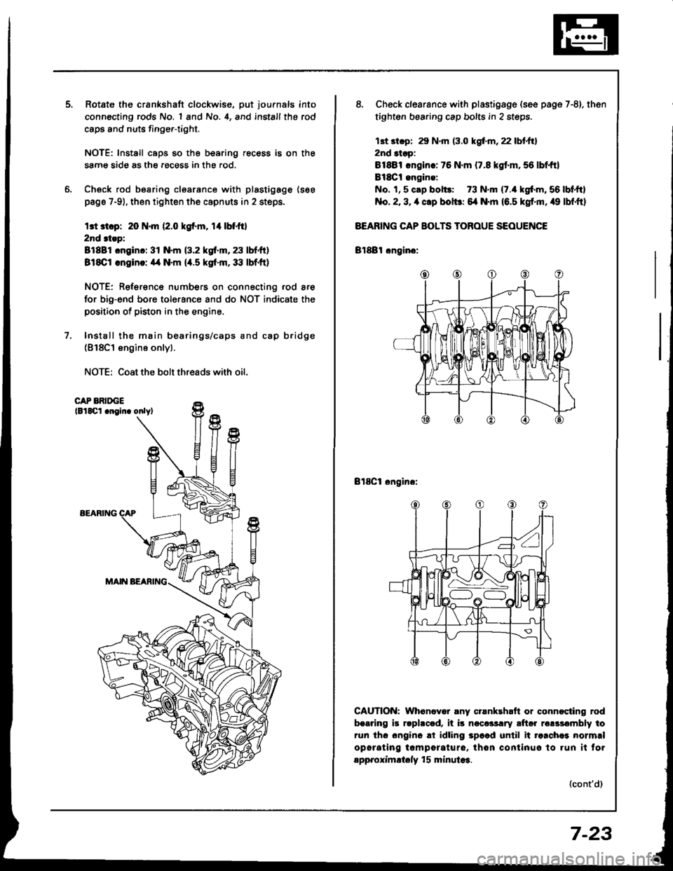
Rotate the crankshaft clockwise, put journals into
connecting rods No. 1 and No. 4, and install the rod
caps and nuts finge.-tight.
NOTE: lnstall caps so the bearing recess is on the
samg side as the .ecess in the rod.
Check rod bearing clsarance with plastigage (see
page 7-9), then tighten the capnuts in 2 steps.
l3t 3t.p: 20 N.m (2.0 kgf.m, rl btfil
2nd 3tep:
81881 cnginc: 31 N.m (3.2 kgf.m, 23 lbf.ft)
818C1 .ngin!: ,14 N.m (4.5 kgt.m,33 lbf.ft)
NOTE: Reference numbers on connecting rod are
for big-end bore tolorance and do NOT indicate the
positioo of piston in the engine.
Install the main bearings/caps and cap b.idge(818C1 engine onlyl.
NOTE: Coat the bolt threads with oil.
CAP BRIDGElBlSCl .noin. onlyl
EEARIlTG
8. Check clearsnce with plastigsge (see page 7-8). then
tighten bearing cap bolts in 2 steps.
13t st.p: 29 N.m (3.0 kgf.m, 22 lbt.ftl
2nd 3tsp:
81881 .ngin.: 76 N.m (7.8 kgt.m,56 lbf,ft)
Bl8Ct engine:
No. 1, 5 cap bol$: 73 N.m (7./r kgf'm, 56 lbf,ftl
No. 2, 3, a clp bolbr 6{ N.m (6.5 kgf'm, /r9 lbf,ftl
BEARING CAP BOLTS TOROUE SEOUENCE
Bl88l cngino:
Bl8Cl ongino:
CAUTION: Whenever any crsnkehaft or connocting rod
b.aring is rlphccd. it i5 ncccrsrry aftor rclssombly to
run tho ongino ai idling 3p6ad until it re.chei normrl
opcrating tcmporature, thon continuo to run it fol
spp.oximltoly f 5 minula3.
(cont'd)
7-23
Page 331 of 1413
Glutch
Speciaf Tools ........ ........ 12-2
fffustrated Index ........ .... 12-3
Clutch Pedal
Adjustment ................12-4
Clutch Master Cylinder
Removal/lnstallation .... 12-5
Slave Gylinder
Removal/lnstallation .... 12-6
Pressure Plate
Removal/lnspection ..... 12'7
Clutch Disc
lnspection/Removal ..... 12-8
Flywheel, Flywheel Bearing
fnspection . 12-9
Replacement ............................... 1 2-9
Clutch Disc, Pressure Plate
Installation 12-10
Release Bearing
Removal/lnspection12-11
Page 333 of 1413

lllustrated Index
NOTE:
a Whenever the transmission is removed, clean and grease the release bearing sliding sudace.
a It the pans marked r are removed. the clutch hydraulic system must be bled (see page 12-6).
a Inspect the hoses lor damage, leaks, interterence, and twisting.
*RESERVOIR
HOSEASSISI SPRING
PEDAL PIN
CLUTCH PEDALAdjustment,page 12-4
15 N.m 11.5 kgl.m,11 tbt.ftl
6 x 1,0 mm9.8 N.m ll.0 ksf.m, 7 lbf.tt)
FLYWHEELInspection. page 12-9Replacement, page 12-9
TCLUTCH MASTER CYLINDERRemoval/lnstallation, page 1 2-5
19 N.m ll.9 kgt.m,14 lbf.ftl
.CLUTCH PIPE
15 N.m {1.5 kgl.m,1 1 rbf.ft)
ICLUTCH PIPE
JOtt{T
8 x 1.25 mm25 N.m (2.6 kgl.m,19 lbt.ttl
RELEASE BEARINGRomovaf /lnspection, page 1 2-1 1lnstaffation, page 1 2- 1 2
TRANSMISSIONRomoval. see
CLUTCH DISCRemoval/lnspection. page'1 2-8Installation, page 12-10
8 x 1.25 mm22 N.m (2.2 kgf.m.16 lbl.rr)
section 1312 x 1.0 mm103 N.m llO.5 kgt.m,76 rbf.ftl
PRESSURE PLATERemoval/lnspection. page 1 2-7Installation, page 12,10
TSLAVE CYLINDERRemovaf /lnstallation. page 1 2-632 N.m {3.3 kgf'm,24 tbf.ftl
15 N. m {1.5 kgf.m,'| I tbf.ftl
COTTERBeplace.
I
NInl
9t
v-_fl
ICLUTCH
12-3
Page 337 of 1413
Pressure Plate
RING GEAR HOLDER07LAB-PVOOl OO or07924-PD20003
Removal/lnspection
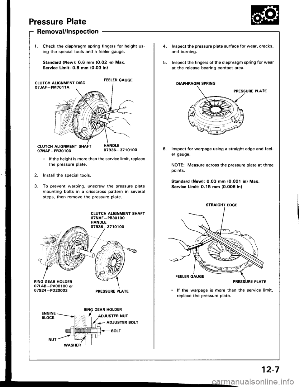
Check the diaphragm spring fingers for height us-
ing the special tools and a feeler gauge.
Standard lNew): 0.6 mm (0.02 inl Max.
Service Limit: O.8 mm {O.O3 in}
FEELER GAUGE
07NAF-PR3010007936-3710100
. lf the height is more than the service limit, replace
the pressure plate.
2. Install the special tools.
3. To prevent warping, unscrew the pressure plate
mounting bolts in a crisscross pattern in several
steps, then remove the pressure plate.
CLUTCH ALIGNMENT SHAFT07NAF-PR30100HANDLE07936-3710'l OO
PRESSURE PLATE
CLUTCH ALIGNMENT OISCOTJAF_PM7011A
4.Inspect the pressure plate surface
and burning.
Inspect the fingers of the diaphrag
at the release bearing contact ar
DIAPHRAGM SPRING
Inspect for warpage using a stru
er gauge.
NOTE: Measure across the prer
pornls.
Standard (Newl: 0.03 mm (0.0
Sorvice Limit:0.15 mm (0.0O6
STRAIGHT EOGE
FEELER GAUGE
PI
lf the warpage is more than
replace the pressure plate.
6.
I surface for wear, cracks,
diaphragm spring for wear
nracr area.
PRESSURE PLAT€
straight edge and feef
pressure plate at three
0.001 in) Max.
)O6 inl
12-7
Page 339 of 1413
InspectionReplacement
Flywheel, Flywheel Bearing
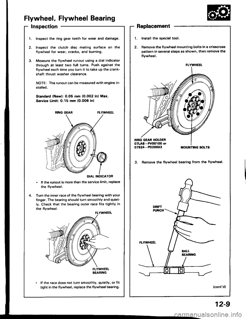
Inspect the ring gear teeth for wear and damage.
Inspect the clutch disc mating surface on the
flywheel fo. wear, cracks, and burning.
Measure the flywheel runout using a dial indicator
through at least two full tu.ns. Push against the
Ilywheel each time you turn it to take up the crank-
shaft thrust washe. clearance.
NOTE; The runout can be measu.ed with engine in-
stalled.
Standard (ttlervl: O.O5 mm (O.002 inl Max.
Service Limit: 0.15 mm 10.006 inl
RING GEABFLYWHEEL
DIAL II{DICATOR
It the runout is more than the service limit, leplace
the flvwheel.
Turn the inner race of the flywheel bearing with your
finger. The bearing should turn smoothly and quiet-
ly, Check that the bearing outer race fits tightly in
the flvwheel.
FLYWHEELBEARING
It the race does not turn smoothly, quietly, or fit
tight in the flywheel, replace the flywheel bearing.
Install the special tool.
Remov€ the flywhe€l mounting bolts in a criascross
pattern in several steps 8s shown, then remove the
tlywheel.
MOUI{TII{G BOLTS
3. Remov€ the flywheel bsaring from th€ tlywheel.
(cont'd)
FLYWHEEL
12-9
Page 340 of 1413
Clutch Disc,
l.
t
Flywheel, Flywheel BearingPressure Plate
Replacement (cont'd)Installation
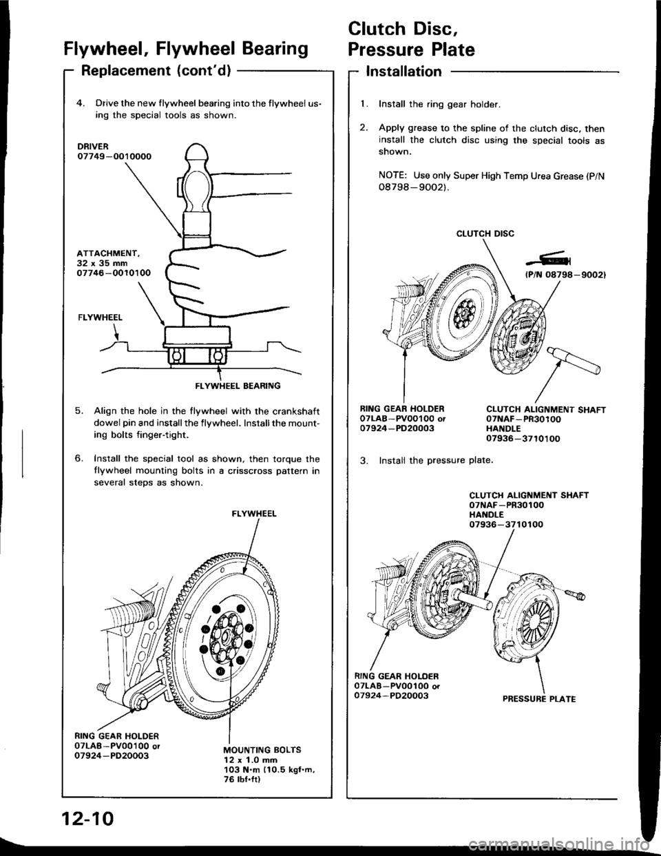
Install the ring gear holder.
Apply grease to the spline of the clutch disc, theninstall the clutch disc using the special tools assnown.
NOTE: Use only Super High Temp Urea Grease (P/N
08798-9OO2).
CLUTCH DISC
RING GEAR HOLDEROTLAB-PVOOI O0 ot07924-PD20003
3. Instali the pressure
CLUTCH ALIGNMENT SHAFT07NAF-PR30100HANDLE07936-3710100
plate.
CLUTCH ALIGNMENT SHAFToTNAF-PR30100HANDLE
PRESSURE PLATE
12-10
4. Drive the new flywheel bearing into the flywheel us-
ing rhe special tools as shown.
DRIVER07749-O010000
ATTACHMENT.32x35mm07746-OOlO100
o.
5.
FLYWHEEL
Align the hole in the flywheel with the crankshaft
dowel pin and installthe flywheel. Installthe mount-
ing bolts finger-tight.
Install the special tool as shown, then torque the
flywheel mounting bolts in a crisscross pattern in
several steDs as shown.
MOUNTING BOLTS12 x 1.0 mm103 N.m 110.5 kgf.m,76 tbf.fr)
FLYWHEEL BEARING
FLYWHEEL
07936-3710100
t\_