Page 639 of 1413

Steering Column
Installation (cont'dl
Finaltorque:22 N.m{2.2 kgf.m, 16lbt.ftl
CAUTION:
. All SRS electrical wiring hrrnossos are covgrod wilhyellow insulation,
. When disconn€cting the SRS wire harness, installthe short connector on the airbag. th€n dbconnoct
the wire harness.
. Replaca the entire alfected SRS harness assembly if
there is an open circuit or damage to tho wiring.
1. Slip the upper end of the steering joint onto the col-
umn shaft {line up the bolt hole with the flat on the
shaft), and loosely install the upper steering joint
bolt.
UPPER STEERING JOINT BOLTBolt must line up withflat on shaft.
STEERINGJOINT
Slip the lower end of the steering joint onto the pin-
ion shaft. Line up the bolt hole with the groove
around the shaft) and loosely jnstallthe lower bolt.
NOTE:
. Be sure that the lower steering joint bolt. is
securely in the groove in the steering gearbox
pinion.
. Before tightening the steering joint bolts, pull on
the sleering joint to make sure that the steeringjoint is fully seated.
LOWER STEERING JOINT BOLTFin6ltoroue:22 N.m {2.2 kgt m. 15 lbf.ftl
17 -32
Install the steering column with the flange nuts,then installthe column holder and flange bolts.
Tighten the upper and lower steering joint boltsloosely installed in steD 2,
FLANGE BOLTS22 N.m12.2 ksi.m, 16 tbtftl
Install the steering joint cover with the clamps andclip.
CLIP
Page 640 of 1413
7.
Connect the ignition switch wire connectors to the
under-dash fuse/relav box.
Install the combination switch and turn signal can-
celing sleeve onto the steering column.
NOTE: Be sure the wires are not caught or pinched
by any parts when installing the combination
switch.
TURN SIGNAL CANCELINGSLEEVE
Install the cable reel onto the steering column, then
connect the SRS main harness and cable reel wiro
harness and install the connector holder.
NOTE: Align the slot in the cable reel with the pro-
jection on the canceling sleeve.
coMatNATroN swncH
UPPER COLUMN COVER
9. Installthe column covers.
scREws
lnstall the driver's knee bolster.
lnstall the lower cover.
Installthe steering wheel {see page '17-26).
10.
11.
't2.
17-33
Page 652 of 1413

Steering Gearbox
Removal
NOTE: Using solvent and a brush, wash any oil and dirt
off the valve body unit, its lines, and the end if the gear-
box. Blow dry with compressed air.
1. Drain the power steering fluid as described on page
17 -21.
2. Rsise the front of car, and support on safety stands
in the propsr locations (see section 1).
3. Remove the front wheels.
il. Removs the st€ering joint cove.,
SIEERING JOIi{T COVEB
Remove the steering joint lower bolt, and move thejoint toward the column.
NOTE: Lock the steering shaft with the ignition key
to retain the steering shaft position.
Remove the cotter pin trom the castle nut and
removo the nut.
Installthe 10 mm hex nut on the balljoint.
Be sure that ths 10 mm hex nut is flush with the ball
ioint pin end, or the threaded section of the ball
ioint pin might be damaged by the ball iointremover.
NOTE: Remove the ball joint using the Ball Joint
Remover, 28 mm {07MAC - 5100200}. Refer to page
l8-11 fot how to use the ball joint rcmover,
Separat€ the tie-rod ball joint and knuckle using the
soscialtool.
CAUTION: Avold d.maging th. blllloint boot.
BALL JOlt{T REMOVER. 28 mm07MAC - SLqt2|X)
Disconnect the shift linkage {MfI model: see section
13, A/[ model see section 14).
Disconnect the heated oxygen sensor (H02S) con-
ngctor, and separate the three way catalytic conver-
ter by removing the s€lf-locking nuts.
NOTE: Always replace the gaskets with new ones.
OXycEt{S€NSOnOONNECTOR SELF.LOCKINGNUT
{cont'd)IHREE WAYCA?ALYTIC CONVERTEN
8.
10.
HEATED
Replacs.
17-45
Page 1000 of 1413

Dashboard
Component Removal/lnstallation
SRS wire harnesses are routed near the dashboard andsteering column.
CAUTION:
a All SRS olectrical wiring harnesses ar6 covolodwith yallow insulation.
a Betoro disconnecting any paft ot th6 SRS wiro
harn€ss, connoct th€ shoi connectots (s66 page
23-2721.
a Replaco th€ entire Itlocted SRS hsrness asaem-
bly il h has an open circuh or damagod wiring.
CAUTION: Whan prying with a flat tip scrowdiv... wrapit with protoctiv€ tape, and apply protectivo tapo a.oundth€ felatsd parts. to provent damag€.
Instiumont p8n6l, Dashboad lower covor. Knec bobtcframoval:
l. Lower the steering column.
2. Remove the screws and detach the cliDs, then re-
move the instrument panel.
3. Remove the coin oocket.
4. Remove the screws and detach the clips, then re-
move the dashboard lower cover.
Disconnect the connector.
: Scrawlocation3, 5
AIF|]A\g)
A i Clip locationg
AA: Cllp, 2 B> : Clip, 2
I l-l L'l| ,-__-, )
itrvi
) 4Z)
_:n,,4<-ft
INSTRUMENT PAI{EL
(cont'd)
COIN POCKET
20-131
Page 1005 of 1413

Dashboard
Replacement Precautions
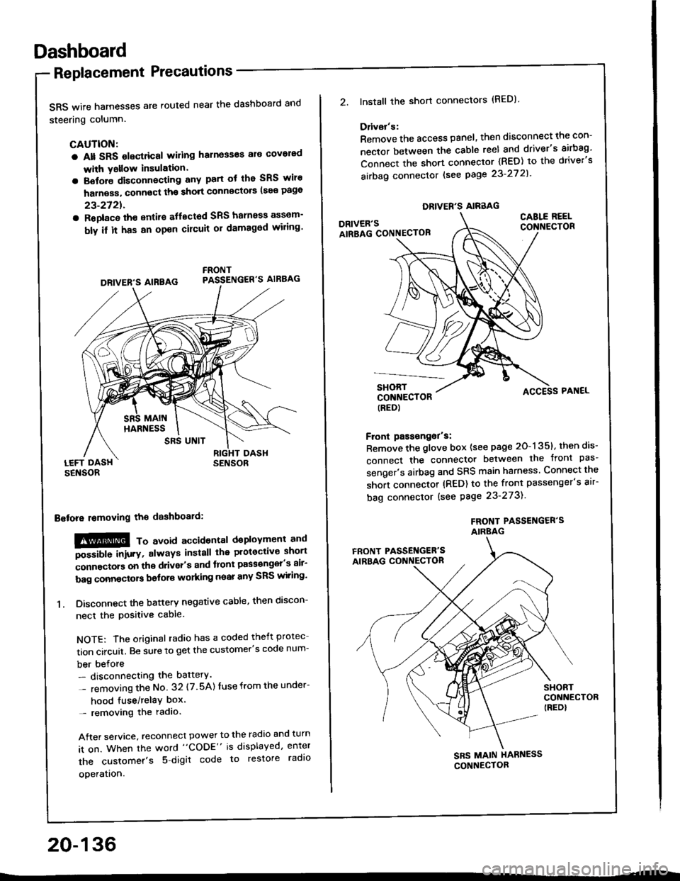
SRS wife harnesses are routed near the dashboard and
steering column.
CAUTION:
a Alt SRS olectrical wiling harness€s ale covorad
with Yollow insulation.
a Botore disconnecting any part ot the SRS wiro
harness, connect ths short connscto6 (see page
23-2721.
a Roplac6 ih€ entiro aflectod SRS halnoss assem-
bly il it has an opon cilcuit or damagod wiling'
LEFT DASHSENSOR
Bstora lomoving the dashboaid:
!@@ To avord accioenlal dsployment and
""iUU inir.v, always install the plotoctive short
;onnectors on the driver's and tlont pass€ngel's air-
bag connectors bolors working near any SRS wiring'
1. Disconnect the battery negative cable, then discon-
necl the positive cable.
NOTE: The original radio has a coded theft protec
tion circuit. Be sure to get the customer's code num-
ber before- disconnecting the battery.
- removing the No 32 (7.5A) Iuse from the under-
hood fuse/relaY box'- removing the radio.
After service, reconnect power to the radio and turn
it on. When the word "CODE" is displayed, enter
the customer's 5 digit code to restore radlo
ooeration.
DRIVER'S AIREAG
SRS UNIT
20-136
DRIVER'S AIRBAG
2.lnstall the short connectors (RED)
Ddvar's:
Remove the access panel, then disconnect the con-
nector between the cable reel and driver's airbag'
Connect the short connector (RED) to the driver's
airbag connector lsee page 23-27 2l'
DRIVER'SAIRBAG CONNECTOB
CABLE REELCONNECTOR
SHORTCONNECTOR(RED)
Front passongor's:
Remove the glove box {see page 20-135}, then dis-
connect the connector between the tront pas'
senger's airbag and SRS main harness Connect the
short connector (RED) to the front passenger's air-
bag connector (see Page 23-273).
FROf{T PASSENGER'SAIRBAG
ACCESS PAI{EL
FRONT PASSET{GER'SAIRBAG CONNECTON
SHORTCONNECTOR(REDI
SBS MAIN HARNESS
CONNECTOR
Page 1006 of 1413

Replacement
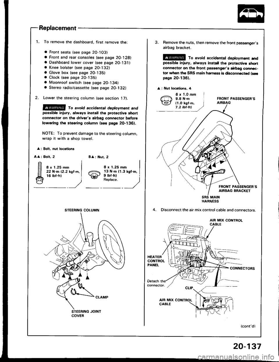
To remove the dashboard, first remove the:
a Front seats (see page 2O-103)
a Front and rear consoles (see page 20-128)a Dashboard lower cover (see page 2O-131)a Knee bolster (see page 2O-132)a Glove box lsee page 2O-135). Clock (see page 20-135)
a Moonroot switch (see page 20-1341a Stereo radio/cassette {see page 20-132)
Lower the steering column (see section 17).
@@ ro avoid accidentat dedoyment andpossiblo in ury, always install the prot€ctive short
connector on tho drivsr's airbag connector bgtor€
lowering tho stooring column (so€ page 20-1361.
NOTE: To prevent damage to the steering column,
wrap it with a shoD towel.
: 8olt, nul locations
A
: Bolt, 28 : ut, 2
8 x 1.25 mm22 N-m 12.2 ksl.m,16 lbt.frl
8 x 1.25 mm
gill$"'l
STEERING COLUMN
3. Remove the nuts, then remove the front passsnger,s
airbag bracket,
@ To avoid accidantar daploym.nr ",'dpossibls iniury, always install th€ protoctiv. 3hqtconnoctor on tho ,ront passongor'a airbag conncc-tor whon tha SRS main ha.na$ is disconncctod llcrpago 20-136).
: Nut locatlons, 4
FRONT PASSENGER'S
FRONT PASSENGER'SAIRBAG BRACKET
4.
SRS MAINHARNESS
Disconnect the air mix controlcable and connectors.
AIR MIX CONTROLCAELE
CONNECTORS
(cont'dl
20-137
Page 1037 of 1413

Heater and Air Conditioning
Heater ........ 21-1
Air Conditioning .......... ..22-1
SUPPLEMENTAL RESTRAINT SYSTEM {SRS}
The Integra SRS includes a driver's airbag, located in the steering wheel hub. In addition. all models except the
RS model for Canada have a front passenge.'s airbag located in the dashboard above the glovs box. Information
necessary to safely service the SRS is included in this Service Manual. ltems msrk€d with an asterisk (') on the
conlents page include, or are located near, SRS components. Servicing, disassembling or,eplacing thes€ items
will require special precautions and tools, and should therefore be done by an authorized Acura dealer.
a To avoid r6nd6dng tho SRS inoporativo. which could lead to personal injury or dealh in tho svont ot a sevele
frontal collision, all SRS servica work musl b€ portormed by an authorized Acura dealer.
a lmpropor sorvico procaduro3, including incorrect romoval and installatlon of tho SRS, could load to porsonal iniu-
ry causod by uninlonlional activation of tho ailbag8.
a All SRS eloctdcal widng harnossos are covored with yollow in3ulation. Relatsd compononts a.o locatod in tha
stsering column, flont console, daehboard, and dashboafd low6r pan6l, and in lhe dsshboa.d above lh€ glove
box. Do not uao electdcal tost equipmont on theae circuhs.
NOTE: The original radio has a coded theft protection circuit. Be sure to get the customer's code number beto.e
- disconnecting the battery.- removing the No. 32 (7.5 A) luse from the under-hood fuse/relay box.- removing the radio.
After service, reconnect power to the radio and turn it on. When the word "CODE" is displayed, enter the cus-
tomer's 5-digit code to restore radio operation.
Page 1177 of 1413

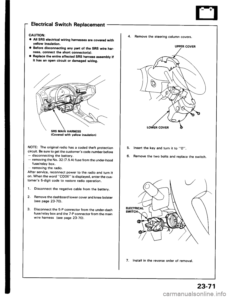
Electrical Switch Replacement
a All SRS €lectric8l wiring hamosses ar€ covorsd withyellow insulation,
a Befora disconnecting any pan of tho SRS wilo har-neas. connect the short connoctor(sl.a R6place the entire attect6d SFS harness assombly ifit has an opon circuit 01 damaged wiling.
NOTE: The original radio has a coded theft protection
circuit, Be sure to get the customer's code number before- disconnecting the battery.- removing the No. 32 (7.5 Al fuse from the under-hoodluse/relay box.- removang the radio.
After service, reconnect power to the radio and turn iton. When the word "CODE" is displayed, enter the cus-tomer's 5-digit code to restore radio ope.ation.
1. Disconnect the negative cable from the batery.
2. Remove the dashboard lower cover and knee bolster
{see page 23-70).
3. Disconnect the 5-P connector from the under-dashfuse/relay box and the 7-P connector from the mainwire harness (see page 23-70).
E
4. Remove the steering column covers.
Insert the key and turn it to ,,O',.
Remove the two bolts and replace the switch.
UPPER COVER
7. Install in the reve.se orde. of removat.
23-71