1994 HONDA INTEGRA radiator cap
[x] Cancel search: radiator capPage 186 of 1413

lllustrated Index
@ sy"t". is under high plessure when engine
is hot. To avoid dsnger of relsssing scalding engine
coolant. remove cap only when engine is cool.
Total Cooling System Capacity (lncluding heater and
r€servoirl
Bl8Bl engine:
Mfl: 6.4 | {6.8 US qt, 5.6 lmp qt}
AlTt 6.7 | {7.1 US qt, 5.9 lmp qt}
Bl8Cl engine:
Mfi: 6.7 t {7.1 US qt, 5.9 lmp qt}
CAUTION: lf any engine coolant spills on paint€d por-
tions ot the body, rinse it ofl immediately.
NOTE:
a Check all cooling system hoses for damage. leaks or
deterioration and replace if necessary.
a Check all hose clamps and retighten if necessary.
a Use new O-rings when reassembling.
CONDENSERFAN SHROUD{soe soction 221
6 x 1.O mm7 N.m (O.7 kgt.m. 5 lbf.ftl
ATF COOLERHOSES{81881 6ngine)
RADIATOREngine coolant refilling and bleeding,page 10-5Leak test, page 'l0-6
Inspect soldered joints andseams for leaks.Elow out dirt from betweencore fins with compressed air.lf insects, etc., are clogging.adiator, wash them off withlow pressure water,
S!
P
R
U
COOLANTRESERVOIR
5x0.8mm4.4 N.m (O.45 kgf.m,3.3 lbl.fr)
M/T: Manual t.anamiaaionA/T: Automatic t.ansmiasionATF: Automatic t.ansmission fluid
\*
*)
FAN SHROUD
10-2
Page 188 of 1413

Radiator
Replacement
1.Drain the engine coolant.
Remove the upper and lower radiator hoses, and ATF
cooter noses.
Disconnect the fan motor connectors.
Remove the radiator upper brackets, then pull up the
radiator.
5. Remove the fan shroud assemblies and other parts
from radiato..
lnstall the radiator in the reverse order of removal:
NOTE:
a Set the upper and lower cushions securely.
a Fill the radiator and bleed the air.4.
UPPER BRACKETAND CUSHTOl{
RADIATOR CAP
t
e
6 x l.O mm9.8 N.m (1.O kgt.m,7.2 rbf.ft)
6 x 1.0 mm9.8 il.m 11.O kgt'm,7.2 lbr.ftl
FAN MOTOR
CUSHION
SHROUDO-RINGReplace.
6 x 1.0 mm9.8 N.m ('l.O kgl.m,7.2 tbl.ttl
DRAIN PLUG
LOWER RADIATORHOSE
Page 189 of 1413

@ ne-oving the radiator cap while the engine
is hot can cause the engine coolant to splay out, seri-
ously scalding you. Always let the engine and radiatol
cool down betore removing the radiator cap.
CAUTION: When poudng engine coolant, be sure to shut
the relay box lid and not to let coolant spill on the elec-
tlical pans or the paint. ll any coolant spills, rinse it otf
immediately.
1. Slide the heater temperature control lever to maxi-
mum heat.
Make sure the engine and radiator are cool to the
touch.
2. Remove the radiator cao.
3. Loosen the drain plug on the bottom of the radiator,
and remove the drain bolt from the enoine block. Let
the coolant drain out.
ENGINE DRAIN BOLT78 N.m {8,O kgt.m, 58 lbt.ftlApply liquid gasker tobolt thread when installing.WASHERReplace.
5.
Remove the reservoir from its holder by pulling it
straight up. Drain the coolant, then put the reservoir
back in its holder.
When the coolant stops draining, apply liquid gasket
to the drain bolt threads, then reinstallthe bolt with
a new washer. Tighten it securely
6. Tighten the radiator drain plug securely.
7. Mix the recommended antifreeze/coolant with an
equal amount of water in a clean container.
NOTE:
. Use only HONDA-RECOMMENOED antifreeze/
coolant.
a For best corrosion protection, the engine coolant
concentrations must be maintained year-round at
50% MINIMUM. Coolant concentrations less than
50% may not provide sufficient protection
against corrosion or freezing.
CAUTION:
a Do not mix ditterent blands ot anti-freeze/
coolants.
a Do not use additional rust inhibitois or anti-rust
products; they may not bs compatibl€ with the
recommgndsd engins coolant.
Engin€ Coolant Retill Capacity: including reservoir
{0.6 t (0.6 US qt, 0.5 lmp qt)).
81881 engine:
MlTt 4.4 | (4.6 US qt, 3.9 lmp qr)
Afft 4.7 [ (5.O US qt,4.1 lmp qt]
Bl8Cl engine:
Mnt 4.7 | (5.0 US qt.4.1 lmp qt)
8. Pour coolant into the radiator up to the base of the
filler neck.
9. Loosen the bleed bolt on top of the engine. Tighten
it again when coolant comes out in a steady stream
with no bubbles.
BLEED BOLT
1O. Refill the radiator to the base of the tiller neck. Put
the cap on the radiator. and tighten it only to the tirst
stop, Stan the engine and let it run until it warms
up (the radiator cooling fan comes on at leasttwice).
11. Turn oft the engine. Check the level in the radiator,
and add coolant it needed. Install the radiator caD,
and tighten it fully.
'1 2. Fill thereservoirto the MAX mark. lnstallthe reser-
voir cap.
9.8 N.m (1.O kgl.m, 7.2 lbf.ftl
Engine Coolant Refilling and Bleeding
10-5
Page 190 of 1413

Radiator
Cap Testing
1.Remove the radiator cap, wet its seal with engine
coolant, then install it on the pressure tester.
Apply a pressure ol:
93- 123 kPa(O.95- 1.25 kgJ/cm', 13.5- 1 7.8 psi)
Check for a drop in pressure.
2.
3.
PRESSURE TESTER
Pressure Testing
1.Wait until the engine is cool, then carefully remove
the radiator cap and fill the radiator with engine
coolant to the top of the filler neck.
Attach the pressure tester to the radiator and apply
a pressure of:
93- 1 23 kPa(O.95- 1.25 kgf/cm,. 13.5-17.8 psi)
Inspect for engine coolant leaks and a dfop in
pressure,
Remove the tester and reinstall the radiator cap.
NOTE:
a Check for engine oil in the engine coolant and/or
coolant in the engine oil.
a Check for ATF in the engine coolant and/or
coolant in the ATF (A/T).
10-6
Page 1059 of 1413

Heater Unit
Replacement
CAUTION:
a All SRS electrical witing hame$os are covoed wlth
yollow insulation.
a Before disconnecting any patt of tho SRS wito har-
neas, connect tha shott connoctol(s|.
a Roplaco th€ enlire sffacted SRS harnosr a$smbly if
it has an opon cilcult or dsmaged wiring.
NOTE: The original radio h8s a coded theft protection
circuit. Be sure to get the customer's code number betors
- disconnecting the bafterY.
- removing the No. 32 (7.5 A) fuse from th€ under-
hood tuse/relav box.- removing the radio
After service. teconnect power to the radio and turn it
on, when the word "CODE" is displayed, enter the cus-
tomer's 5-digit code to restore radio operation.
1. When the engine is cool, dtain the engine coolant
from the radiator (see section 1O).
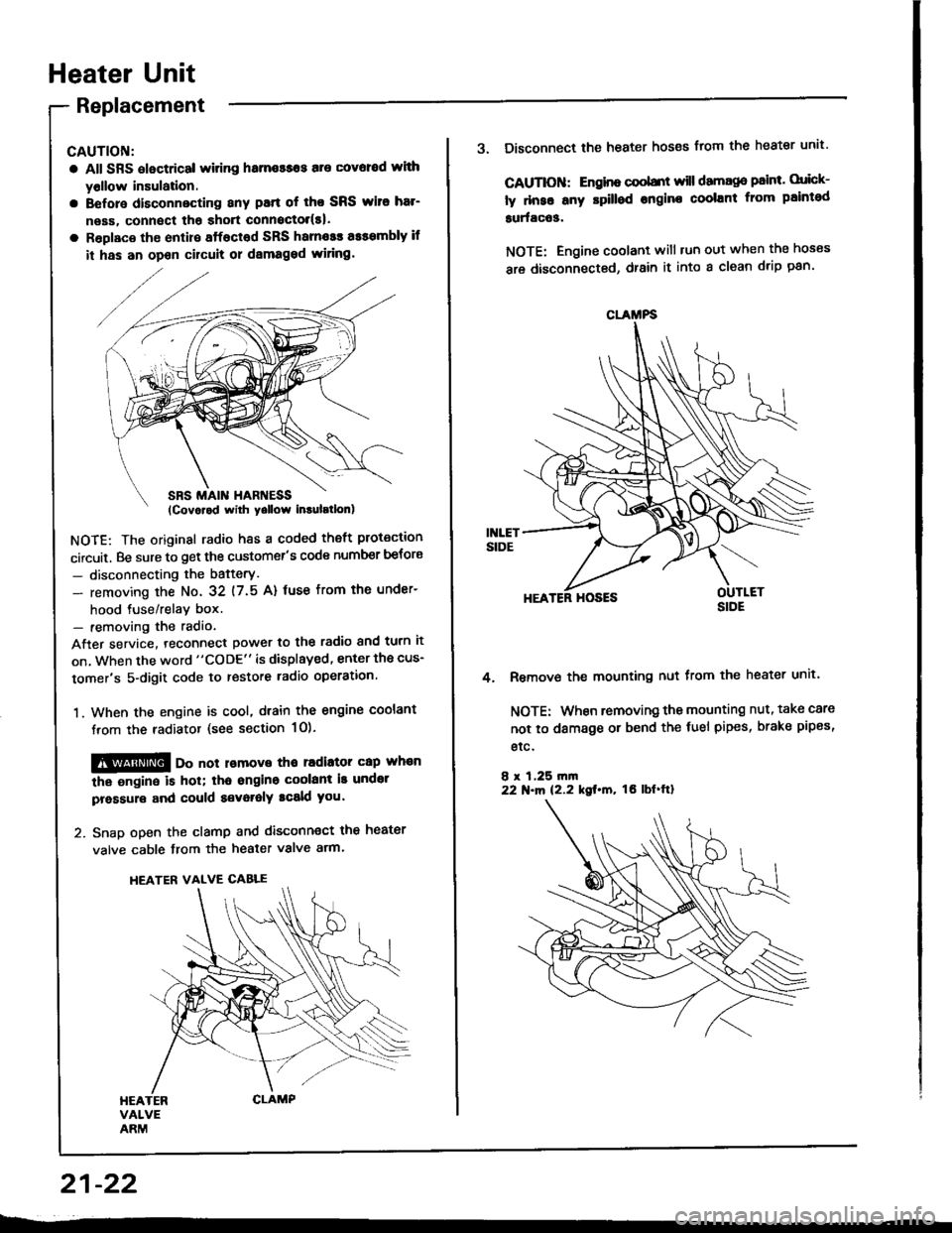
@@ oo not lomove tho radiator cap whan
the ongine is hol; tha ongino coolant is undot
pressure and could a€voralY tcald you.
2. Snap open the clamp and disconnect the heater
valve cable from the heater valve arm.
HEATER VALVE CABLE
21-22
CLAMFS
3. Disconnect the heater hoses from the heater unit'
CAUTIOII: Engino coobnt will damago paint. orick-
ly dnse any rpilled engine coolant from paintod
surfac63.
NOTE: Engine coolant will tun out when the hoses
are disconnected, drain it into a clean drip pan'
HEATER HOSES
Remove the mounting nut from the heater unit.
NOTE: When removing the mounting nut, take care
not to damage or bend the fuel pipes, brake pipes,
etc.
8 r 1,25 rn|n22 N.m 12.2 kgt.m, tO lbf'ftl
4.
Page 1091 of 1413

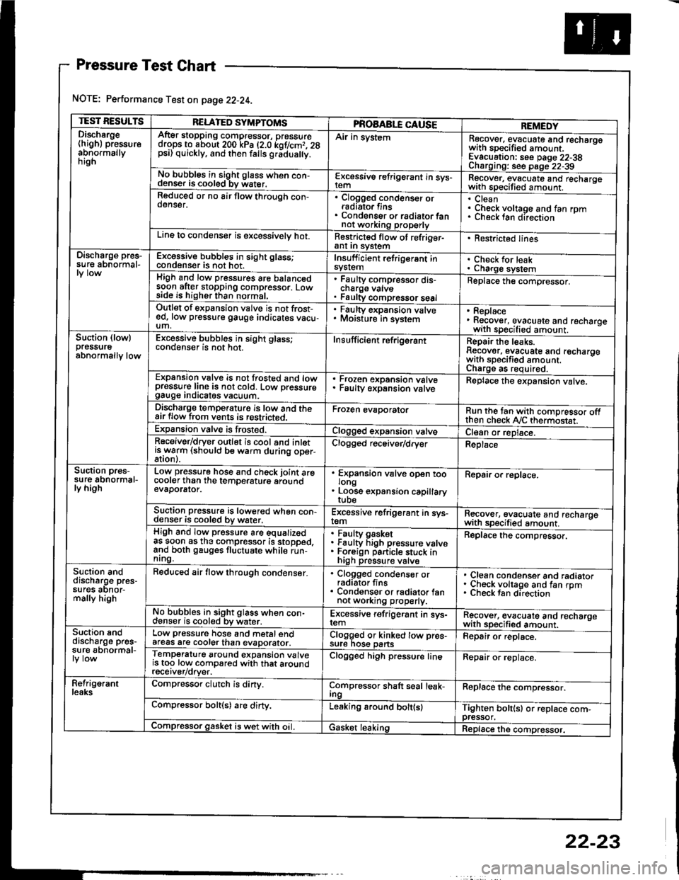
Pressure Test Chart
NOTE: Performance Test on page 22-24.
TEST RESULTSRELATED SYMPTOMSPROAABLE CAUSEREMEDYDischsrge(high) pressureabnormallynrgn
AftEr stopping compressor, pressuredrops to about 200 kPa (2.0 kof/cmr. 28psi) quickly, and then falls gr;dua y.
Air in systemRecover, evacuate and recharqowith sDecified amount. -
Evacuation: see Daqe 22-38Charoino: se6 D;op--2?-?qNo bubbles in sight g16ss when con-denser is cooled bv water.E-\cessive refrigerant in sys-Recover, evacuate and recharqewith specitied amount. -
Reduced or no air flow through con-oenser.Clogged condenser orradiato. finsCondenser o. radiator fannot working properly
CleanCheck voltage and fan rpmunecK lan ofeclton
Line to condenser is excessivelv hot.Restricted flow of refriger-ant In syslem. Restricted lines
Discharge pres-su re abnormal-Excossive bubbles in sight glass;condenser is not hot.Insuff icient refrigerant insyslemCheck for leakCharge systemHigh and low pressures are balancedsoon after stopping compressor. Lowside is higher than normal,
Faulty compressor dis-cnarge vaNsFaulty compressor seal
Replace the compressor.
Outlet of expansion vslve is not frost-ed, low pressure gauge indicates vacu-um,
. Faulty expansion valve. Moisture in sysiem. Replace. Recover, evacuate and recharoewith specified amount. -
Suction (lowlpressureabnormally low
Excessive bubbles in sight glass;conqenser rs not hot_Insuff icient ref rigerantReoair the leaks.Reaover, evacuate and recharoewith sDecifisd amount. -
Charqe as required.Expansion valve is not trosted and lowpressur€ line is not cold. Low pressuregauge Inorcates vacuum.
Frozen expansion valveFaulty expansion valveReplace the expansion valve.
Discharge temperaturg is low and theair flow from vents is restricted.Froren evaporatorRun the tan with comoressor oftthen check Ay'C thermostat.Expansion valve is frost€d.Clogged expansion valveCl€an or replace.Receiver/dryer outlet is cool and inletisrryarm (should be warm during oper-Clogged r€ceiver/dry€rReplace
Suction pres-su re abnormal-ly high
Low pressure hose and check joint arecooler than the temDeraturo aroundevaDorator.
'
ffin"nsion u"lu" oD"n too
. Loose expansion capillary
Repair or replace.
Suction pressure is lowered when con-denser is cooled by water,Excessive refrigerant in sys-remRecover, evacuate and recharqewith sDecifi€d amount. -
High and low pressure are equalizedas soon as the compressor is stopped,and both gauges fluctuate while run-nrng.
Faultv oasketFaulty Figh pressure valveForeign particle stuck inhigh pressure valve
Replace the compressor.
Suction anddischarg€ pres-sufes aonor-mally high
Reduced air flow through condenser.. Clogged condenser orradiator fins. Condenser or radiator fannot working properly.
Clean condenser and radiatorCheck voltage and fan rpmCheck fan direcrion
No bubbles in sight glass when con-cl€nser is cooled bv water.Excessive refrigerant in sys-remRgcover, €vacuate and recharoewith sp€cified amount.Suction snddischarge pres-su r€ abnormal-
Low pressure hose and metal endafeas are cooler than evaDorator.Clogged or kinked tow pre€-sure nos€ pansFepair or replace.
Temperature around expansion valveis too low compared with that aroundrecerver/orver.
Clogged high pressure lineRepair or replace.
Refrig€rantleaksCompressor clutch is dirty.Compressor shaft seal leak-IngReplace the comDressor.
Compressor bolt(s) are dirty.Leaking around bolt(s)Tighten bolt(sl or replace com-pressor.Compressor gasket is wet with oil. IGasket leakingReplace the compressor.
22-23
Page 1103 of 1413

Condenser
Replacement
RAOIATOR UPPENMOUNT BRACKETS
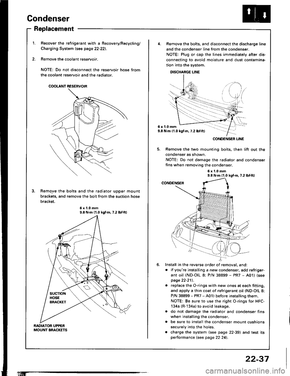
Recover the relrigerant with a Becovery/Recycling/
Charging System (see page 22-221.
Remove the coolant reservoir,
NOTE: Do not disconnect the reservoir hose from
the coolant reservoir and the radiator.
COOLANT RESERVOIR
Remo.ve the bolts and the radiator upper mount
brackets, and remove the bolt from thg suction hose
bracket.
9.8 N.m {1.0 kgf.m.7.2 lbtftl
'1Iffi
22-37
6x1.0mm9.8 N.m (1.0 kgl.m,7.2 lbt.ft)
......-.....
CONOENSER LINE
Remove the bolts. and disconnect the discharge line
and the condenser line from the condenser.
NOTE: Plug or cap the lines immediately after dis-
connecting to avoid moisture and dust contamina-
tion into the system.
DISCHARGE LINE
Remove the two mounting bolts, then lift out the
condenser as shown.
NOTE: Do not damage the radiator and condenser
fins when removing the condenser.
6x1.0mm9.8 N.m (1.0 kgf.m, 7.2 lbl.tt)
Install in the reverse order of removal. and:
. if you're installing a new condenser, add refriger-
ant oil (ND-OIL 8: P/N 38899 - PR7 - A01) (see
page 22-21t,.
. replace the O-rings with new ones at each fitting,
and apply a thin coat of refrigerant oil {ND-OIL 8:
P/N 38899 - PR7 - A01) before installing them.
NOTE: Be sure to use the right O-rings for HFC-
134a (R-134a) to avoid leakage.
a do not damage the radiator and condenser fins
when installing the condenser,
. be sure to install the condenser mount cushions
securely into the holes.
. charge the system (see page 22-39) and test its
performance (see page 22 24!�.