Page 620 of 1413

Unovon or rcugh 8te6ring.
3
Adjust rack guide (se€ poge 17-21).
ll the probl6m is not corrected bYadjusting lhe rack guide. replacothe gearbox.
Adiud bolt t€nsion. Roplace b€lt, ifn€c€ssary {s€e page 17-20).
lf the ongin€ stalls when wheel isturned whil€ car is stoDPed ormoving at low spoed, adjust idlesp€€d (soe section 1 1 ).
ldl6 soosd low or orrrtic.
Chock power sieering Iluid levol. Itlgv6l ie excessivoly low, ch€ck forleaks in the system. Add fluid totho spocifiod level.
Air in rssorvoir. or ch€ck pow6a
steoring fluid l6v6l.
lf fluid lev6l is OK, check o-ringsand seals on both €nds of ihopump inlet hose, and th€ oilpump housing mating surfacosfor suction leaks. Reolace oarts65 n€CeSSAry.
Adjust belt tonsion (see page 17-m) or r€Dlaco beh.Pump b6lt slipping on pull6y(pump stops momontarily).
Check if pump prossure is withinthe ranoe 6.400 - 7,100 kPa (65 - 75kgr/cm,, 924 - 1,067 psil and th6gsuge needls travol is 1500 kPa {15kgflctn2, t71 p6i) or less. Check theflow control valve if the needletr.vel €xcoods 1500 kPa {15kg?cm,, i71 psi). lf rhe flow controlvalvo is normal, replace th€ pump
as an assomblv.
Sel the power itooring p.oasuregaug6. Cl066 th€ shut-off v6lv6fully and m€a5uro tho pumppr6ssur6 (6s€ pagg 17-221,
7-1
Page 628 of 1413

NOTE: Perform rack guide adjustment with the wheels
in the straight ahead position.
Loosen the rack guide screw locknut with the spe-
cialtool, then loosen the rack guide screw.
Tighten the rack guide screw until it compresses the
spring and seats against the .ack guide, then loosen
it.
Retighten the rack guide screw to 3.9 N.m {0.4
kgf'm, 2.9 lbf.ft), then back it off to specified angle.
Specified R6turn Angle: 20 t 5"
Tighten the locknut while holding the rack guide
screw.
1.
6.
RACK GUIDE SCREW
25 N.m12.5 kgf.m, 18lbtftl
L(rcKNUT WRENCH, 40 mm07916 - SAs(xtOl
Check for tight or loose steering through the com-
plete turning travel.
Perform following inspections:
. Steering operation (see page 17-18).
. Power assist with car parked.
Check the reservoir at regular intervals. and add fluid as
necessary.
GAUTION: Use only Genuine Honda Power Stosring
Fluid-V. Using othsr fluids such as ATF or other manu-
facturer's power stoering fluid will damags ths systcm,
SYSTEM CAPACITY:
LO6 litor (1.12 US. qt, 0.93 lmp.qtl
at disasssmbly
RESERVOIR CAPACITY:
0.79 lit6r (0.8:l US. qt, 0.70 lmp.qt)
UPPER LEVEL UNE
LOWER LEVEL LINE
,l
Raise the reservoir and disconnect the return hose
that goes to the oil cooler.
Connect a hose of suitable diameter to the discon-
nected return hose and put the hose end in a suit-
able container.
CAUTION: Tako caro not to 3pill tho tluid on tho
body and parts. Wipe off the spilled tluid at onqe.
Start the engine. let it run at idle. and turn the steer-
ing wheel from lock-to-lock several times. When
fluid stops running out of the hose, shut off the
engine. Discard the fluid,
Refit the return hose on the reservor.
Fill the reservoir to the uDoer level line.
Start the engine and run it at fast idle, then turn the
steering from lock-to-lock several times to bleed air
f.om the system.
Recheck the fluid level and add some if necessary.
CAUTION: Do not lill the roservoir beyond tho
uppgr lovel line.
7.
Page 1018 of 1413

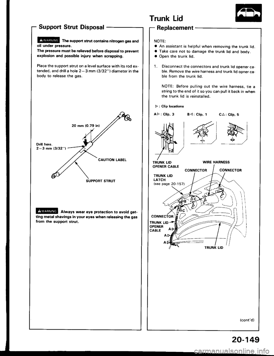
20 mm (O.79 inl
SUPPORT STRUT
Support Strut Disposal
@ Tha support strut contains nitrog.n gas andoil unde. pr€ssul€.
The pressure must be relieved bsfo.e disposal to prevant
explosion and possible injury wh€n sc.apping.
Place the support strut on a level surface with its rod ex-
tended, and drilla hole 2-3 mm (3/32"1diameter in the
body to release the gas.
@ always w€ar €ye prot6ction to avoid get-
ting motal shavings in your eyea when roloasing th€ gas
fiom the support st.ut.
Trunk Lid
TRUNK LIDOPEN€R CABLE
TRUNK LIDLATCH{see page 20-157}
TRUNK LIOOPENERCABLE
CA : Clip, 5
e-i
_rP ,/
Replacement
NOTE:
a An assistant is helpful when removing the trunk lid.a Take care not to damage the t.unk lid and body.a Open the trunk lid.
1. Disconnect the connectors and trunk lid opener ca-ble. Remove the wire harness and t.unk lid opner ca-ble from the trunk lid.
NOTE: Before pulling out the wire harness, tie astring to the end ot it so you can pull it back in when
the trunk lid is reinstalled.
> : Clip locationg
AD : Clip, 3 B< : Clip, 1
WIRE HARNESS
CONNECTORCONIIECTOR
A
A
(cont'd)
20-149
Page 1219 of 1413
Gauge Assembly
Component Location Index
CAUTION:
a All SRS electrical wiring harnosses are cov€rod withyellow insulation.
a Bofore disconnecting any prn ot th€ SRS wire har-ness, connect tho short connector(sl.a R€place th6 entirs affGcted SRS halne$ assembly ifit has an open circuit o? damaged wiring.
SRS MAIN HARNESS{Cov.r6d with yollow inrularionl
GAUGE ASSEMBLYGauge Location Index, page 23-114Indicator Location Index, page 23-1 14Terminal Location Index, page 23-114Bulb Location. page 23-'l 15Disassembly. page 23-1 19Removal, page 23-118
FUEL GAUGE SENDING UNtTTest, page 23'124Repfacemenr, page 23-124
VEHICLE SPEEO SENSOB IVSS}Test, page 23-120fnput Test. page 23-120Repfacement, page 23-122
PARKITTG BRAKE SWITCHTest, page 23-127
BRAKE FLUID LEVEL SWITCHTesr, page 23-127
EI{GINE OIL PBESSURE SWITCHTest, page 23-122
ENGINE COOLANT TEMPERATURE IECTI GAUGESENOING UNITTest, page 23-126
(C61'ios tho SBS indicator signal)
23-113
Page 1228 of 1413

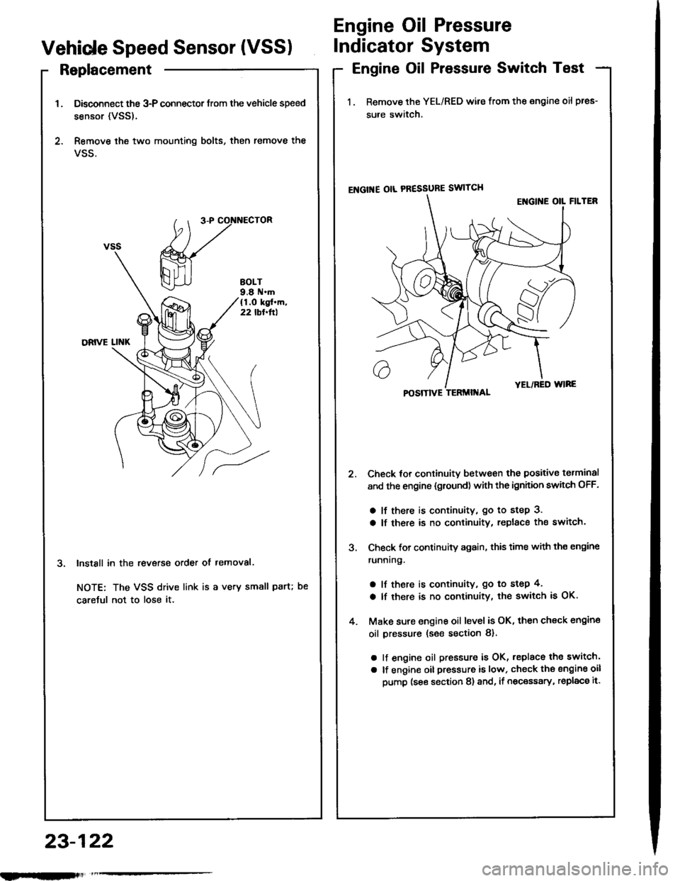
Replacement
Disconnect the 3-P connector trom the vehicle speed
sensor {VSS).
Remove ihe two mounting bolts, then remove the
VSS.
InstSll in the revsrse order of removal.
NOTE: The VSS drive link is a very small paru
caretul not to lose it.
Engine Oil Pressure
Vehide Speed Sensor (VSSIIndicator System
Engine Oil Pressure Switch Test
1. Remove the YEL/RED wile from the engine oil pres-
sure switch.
ENGI'{E OIL PRESSURE SWITCH
Check tor continuitv between the positive torminal
and the engine {gtound) with the ignhion swhch OFF.
a lf there is continuity, go to step 3.
a lf there is no continuity, replace the switch.
Check for continuity again, this time with th€ engine
runnrng.
a lf there is continuity, go to step 4,
a lf there is no continuity, the switch is OK.
Make sure engine oil level is OK, then check engin€
oil pressure (s€e section 8).
a lf engine oil pressure is OK, replace the switch'
a lf engine oil pressure is low, check the sngine oil
pump (see section 8) and, if necessary, replac€ it.
POSITIVE TERMII{AL
23-122
nlmlliitl