1994 HONDA INTEGRA fuel pressure
[x] Cancel search: fuel pressurePage 203 of 1413

G) FUEL PUI-SATION DAMPER
@ AIR CLEANER(D RESONATOR6 imrlre arR Bypass (tAB) coNTRoL DIAPHRAGM
VALVE(D) IITITP IIN BYPASS {IAB) COTROL SOLENOID VALVE
ds) INTIXT AIR EYPASS TIABI VACUUM TANK
rio'l rnrarg ltn BYPASS (lABl cHEcK vALvE
6 rsnee wav cATALYTtc coNvERTER lrwc)
6 posrnve cRAf{KcAsE vENTILATIoN {Pcv) vALVE
6 evlponlrtve EMtsstot{ tEvAPl coNTBoL cANlsrER
6 evlponltvE EMtssloN {EvAP} PURGE coNTRoL
SOLENOID VALVE6i EVAPORATIV€ EMISSION (EVAPI PURGE CONTROL
DIAPHRAGM VALVE
6o ivlpoalrtve Eutsstof{ IEVAPI rwo wAY vALvE
c) HEATED OXYGEN SENSOR lHO2Sl
€) MANIFOLD ABSOLUTE PRESSURE IMAPI SENSOB
O EI{GINE COOLANT TEMPERATURE {ECT} SENSOR
€) INTAKE AIR TEMPERATURE {IAT) SENSOR
@ KNOCK SENSOR tKSl
@ IDLE alR coNTRoL llAcl vALvE
O FAST IDLE THERMO VALVE
@ FUEL INJECTOR
@ FUEL FILTER
@ FUEL PRESSURE REGULATOR
O) FUEL PUMP (FPI
@) FUEL TANK
@ FUEL TANK EVAPORATIVE EMISSION IEVAPI VALVE
11-11
Page 228 of 1413

Troubleshooting
Self-diagnostic Procedures (cont'dl
':818C1 engine
a lf codes other than those listed above are indicated, verifv the code. lf the code indicated is not listed above, replace
rhe ECM.
a The MIL may come on, indicating a system problem when, in fact, there is a poor or intermittent electricalconnection.
First, check the electrical connections, clean or repair connections it necessary.
o The MIL and @ indicator light may light simultaneously when the Diagnostic Trouble Code (DTC) 6, 7 or 17. Check
the PGM-Fl system according to the PGM-Fl system troubleshooting, then recheck the l!! indicator light. ll it lights,
see page 14-5O, 51.
a The MIL does not come on when there is a malfunction in the A/T Fl signal or Electrical Load Detector (ELDI circuits.
However, it will indicate the codes when the Service Check Connector is shorted.
DIAGNOSTIC
TROUBLE
CODE (DTCISYSTEM INDICATEDPsge
oENGINE CONTROL MODULE IECM)11-42
,lHEATED OXYGEN SENSOR IHO25)1 1-46
aMANIFOLD ABSOLUTE PRESSURE {MAP SENSOR)11-52
4CRANKSHAFT POSITION (CKP SENSOR)1 1-56
oENGINE COOLANT TEMPERATURE (ECT SENSOR)11-58
THROTTLE POSITION (TP SENSOR}11-60
ITOP DEAD CENTER POSITION (TDC SENSORI1 1-56
9No. 1 CYLINDER POSITION (CYP SENSOR)1 1-56
10INTAKE AIR TEMPERATURE (IAT SENSOR)11-62
13BAROMETRIC PRESSURE (BARO SENSOR}1|-64
14IDLE AIR CONTROL (IAC VALVE}11-42
tcIGNITION OUTPUT SIGNAL11-66
toFUEL INJECTOR1't-102
17VEHICLE SPEED SENSOR {VSSI11-68
20ELECTRICAT LOAD DETECTOR (ELD)'t 1-70
21VARIABLE VALVE TIMING & VALVE LIFT ELECTRONIC CONTROL SOLENOID
VALVE {VTEC SOLENOID VALVE)'6-36
22VARIABLE VALVE TIMING & VALVE LIFT ELECTRONIC CONTROL PRESSURE
SWITCH (VTEC PRESSURE SWITCHI-6-38
23KNOCK SENSOR {KS}-11-7 4
30A/T FI SIGNAL A11-76
3'rA/T FI SIGNAL B1 1-76
4'lHEATED OXYGEN SENSOR (HO25} HEATER11-47
43FUEL SUPPLY SYSTEM1 1-50
11-36
Page 232 of 1413

PGM-FI System
System Description
ENGINE CONTROL MODULE (ECMIOUTPUTS
PGM-Fl System
The PGM-Fl system on this model is a sequential multipon fuel injection system,
Fuol Iniector Timing and Duration
The ECM contains memories tor the basic discharge durations at various engine speeds and manifold pressures. Thebasic discharge duration, after being read out from the memory, is turther modilied by signals sent from vanous sensofsto obtain the final discharge duration.
ldle Air Control
ldle Air Control Valve (lAC Vatve)
When the engine is cold, the A/C compressor is on, the transmission is in gear (A/T only) the brake pedal is depressed,the P/S load is high, or the alternalor is charging, the ECM controls current to the IAC Valve to maintain correct idle soeed.
lgnition Timing Controla The ECM contains mamories for basic ignition timing at various engine speeds and manifold pressures. lgnition timingis also adjusted for engine coolant temperature.a A Knock Control System is also used. when detonation is detected by the knock sensof. the ignition timing is retarded(B18Cl engine).
Other Control Functions
1. Starting Control
When the engine is started. the ECM provides a rich mixture by increasing fuel injector duration.2. Fuel Pump Control
a When the ignition switch is initially turned on, the ECM supplies ground to the PGM-Fl main relay that suppliescurrent to the fuel pump tor two seconds to pressurize the tuel system.a When the engine is running, the ECM supplies gfound to the PGM-Fl main relay that supplies current to the fuel pump.a When the engine is not running and the ignition is on, the ECM cuts ground to the PGM-FI main relav which cutscurrent to the fuel pump.
TDC/CKP/CYP Sensor
MAP Senso.
ECT Sensor
IAT Sensor
TP Sensor
HO2S
vss
BARO Sensor
ELD
Starter Signal
ALT FR Signal
Air Conditioning Signal
A/T Gear Position Signal
Battery Voltage {lcN. 1)
Brake Switch Signal
PSP Switch Signal
Knock Sensor'
VTEC Pressure Switchr
Fuel-lnjectors
PGM-FI Main Relay (Fuel Pump)
MIL
IAC Valve
A/C Compressor Clutch Relay
Radiator Fan Relav
Condenser Fan Relav
ALT
rcM
EVAP Purge Control Solenoid
HO2S Heater
VTEC Solenoid Valve'
IAB Control Solenoid Valve*
lFuet tnjector Timing and Duration]
I Electr..l"ldle Contr;il
Fit'e' contr; Funcrfit
l6tio; Ttntrlg c..trol
tEcM aack-,rp Functiorlsl
': 818C 1 €ngine
11-40
Page 286 of 1413

Fuel Supply System
System Troubleshooting Guide
NOTE: Across each row in the chart, the sub-systems that could be sources of a symptom ara tanked in tho order they
should be inspected starting with O. Find the symptom in the left column, read across to the most liksly source, then
refer to the page listed at the top of that column. lf inspection shows the system is OK, try the next most liksly system
@, etc.
PAGE
SYI\4 PTOM
FUEL
LINES
FUEL
INJECTOR
FUEL
PRESSURE
REGULATOR
FUEL
FILTER
FUEL
PUMP
PGM-FI
MAIN
RELAY
CONTAM'
INATEO
FUEI
11-9811-1021 1,106l1-toa11-109t'l'nl
ENGINE WON'T START@o@
DIFFICULT TO START
ENGINE WHEN COLD OR HOTo\4
ROUGH IDLEo@
POOR PER.
FORMANCE
MISFIRE OR
ROUGH
RUNNINGo@@
FAILS
EMtSSION@o
LOSS OF
POWER@@o
FREOUENT
STALLING
WHILE
WARMING
UPo
AFTER
WARMING
UPo
11-97
Page 289 of 1413

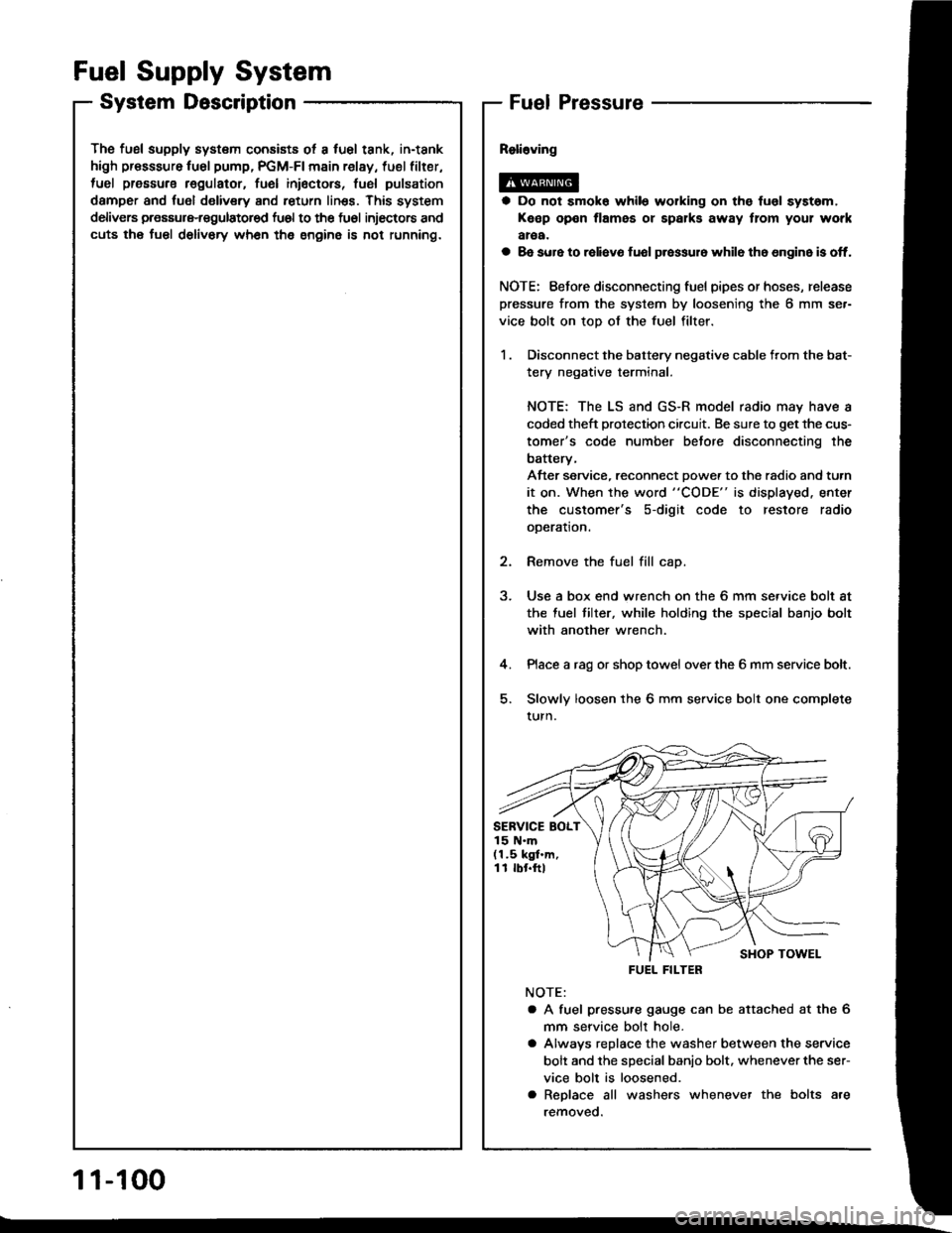
The fusl supply system consists ot a fuel tank, in-tank
high presssure fu6l pump, PGM-FI main relay, fuel filter,
tuel pressure regulatot, fuel inioctors, fusl pulsation
damper and fuol delivery and return linss. This system
delivers pressure-regulatored fu6l to the fu6l injectors and
cuts the fuel delivory wh6n the engine is not running.
Fuel Supply System
System DescriptionFuel Pressure
a Do not smok6 while working on the fuol syst6m,
Keep open flames or spalks away tlom your work
aroa.
a 8e sure to raliavo fuol p.essur6 while th6 6n9in6 is off.
NOTE: Eefore disconnecting fuel pipes or hoses, release
pressure from the system by loosening the 6 mm se.-
vice bolt on top of the fuel filter.
1 . Disconnect the battery negative cable from the bat-
tery negative terminal.
NOTE: The LS and GS-R model radio may have a
coded theft protection circuit. Be sure to get the cus-
tomer's code number betore disconnecting the
batterv,
After service, reconnect Dowe. to the radio and turn
it on. When the word "CODE" is displayed. enter
the customer's s-digit code to restore radio
ooeration.
2. Remove the fuel fill cap.
3. Use a box end wrench on the 6 mm service bolt at
the fuel tilter, while holding the special banjo bolt
with another wrench.
4. Place a rag or shop towel over the 6 mm service bolt.
5. Slowly loosen the 6 mm service bolt one complete
turn.
NOTE:
a A fuel pressu.e gauge can be attached at the 6
mm seryice bolt hole.
a Alwavs replace the washer between the service
bolt and the special banio bolt. whenever the ser-
vice bolt is loosened.
a Replace all washers whenever the bolts are
removeo.
SERVICE BOLT15 N.m(1.5 kgf.m,11 rbr.ftl
FUEL FILTER
1 1-100
Page 290 of 1413

Insp6ction
1. Relieve fuel pressure (see page 11-1OO)
2. Remove the service bolt on the tueltilter while hold-
ing the banjo bolt with another wrench. Attach the
special tool
3. Siart the engine. * Measure the {uel pressur€ with
the engine idling and vacuum hose of the fuel pres-
sure regulator disconnected from the tuel pressure
regulator and pinched.
Pressure should b€;
818B1 engins:
275-324 kPa (2.8-3.3 kgl/cm2, 40-47 psil
818C1 ongine:
329-37a kPa (3.35-3.85 kgf/cmz, 48-55 pei)
4. Reconnect vacuum hose to the tuel plessure
regulator.
Prossuro should b€;
Bl8Bl ongino:
216-245 kPa (2.2-2.5 kgf/cm'�, 31 -36 psil
B18Cl on9in6:
27O-319 kPa 12.75-3.25 kgt/cm'�, 39-46 psi)
FUEL PRESSURE GAUGE07406 - OO4000 1
lf the engine will not stan, turn the ignition switch
on. wait for two seconds, turn it off, then back on
again and read the fuel pressure.
CLAMP
a lf the fuel pressure is not as specified, first check the
fuel pump (see page 1 l - 1 1O). lf the fuel pump is oK,
check the following:
- lf the fuel pressuro is higherthan specified, inspect for:
. Pinched or clogged tuel return hose or line.
. Faulty fuel pressure regulator (see page 11-106)
- It the fuel p.essu.e is lower than specitied, inspect fo.:
. Clogged fuel tilter.. Faulty fuel pressure regulator (see page '11-106).
. Leakage in the fuel line.
1 1-101
Page 291 of 1413

Fuel Supply System
Fuel Injectors
- --l- - \-l-l
116l- -ltc l-/---r- / ---i- \
The Fuel Injectors a.e a solenoid-actuated constant-stroke pintle type consisting of a solenoid, plungel n€edle valvs and
housing. When cur.ent is applied to the solsnoid coil, the vslve litts up and pressurized fuel is injected. Because the nee-
dle valve litt and the luel pressure are constant, the iniection quantity is determined by the length of time that the valv€
is open (i.e., the duration the cu.rent is supplied to the solenoid coill. The Fu€l Iniector is sealed by an O-ring and seal
ring at the top and bottom. These seals also reduce operating nois6.
O.RII{G FUEL RAIL
The Malfunction Indicator Lamp (MlL) indicates Diagnostic Trouble Code (DTC) l6: A problem in
the Fuel lniector circuit.
FILTER
PTUNGER
-_-- - ___L-
IrGl- lto l--|.---:_-
- Tho MIL has boen roportod on.- Wilh tho SCS .hon connocto.conoctod (soo pago 11-34),code 16 is indicalod.
Do the ECM Besel Procedure (seepage l l -351.
Intermittant tailura, aystam ir OKat thir tim. (t..1 drivo m.y b.nocaar!ry1.Ch.ck lor poor connactiona ot100!6 wir6!.t C221 (loortod rtright .hock low.rl, C121,C122,Cl23, Cl24 llu6l InFctorrl, lndECM.
ls the MIL on and does itindicate code l6?
NOTE: lf engine willnot start, it may tak6lO seconds ol cranking to sgt th6 code.
{To page 1 1-1O31
11-102
Page 294 of 1413

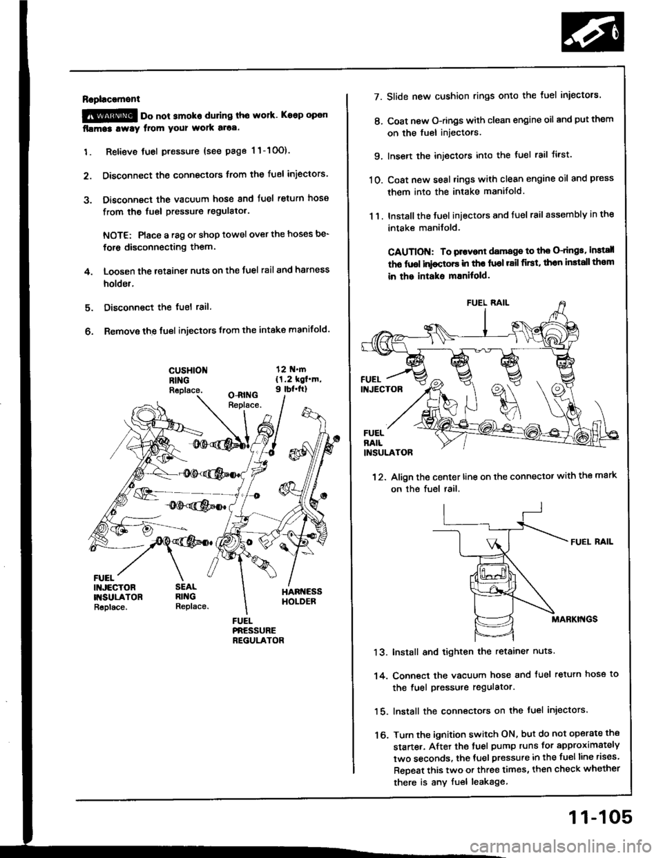
Rapl!c!ment
@ oo not smoko during tho work. Keep open
fllma3 lway from your wolk aloa.
1. Retieve tuel pressure {see page 1 1-10O).
2. Disconnect the connectors trom the fuel iniectors.
3. Disconnect the vacuum hose and fuel return hosa
from the fuel pressure regulatol.
NOTE: Place a r8g or shop towel over the hoses be-
for6 disconnecting them.
4. Loosen the retainer nuts on the Juel rail and harness
holder.
Disconnect the tuel 18il.
Remove the fuel injectors from the intake manifold.
5.
6.
cusHloNRINGReplace.
FUEL
7.
t'.
9.
10.
13.
14.
16.
11.
Slide new cushion rings onto the luel iniectors.
Coat new O-rings with clean engine oil and put them
on the fuel injectors.
Insen the injectors into the tuel rail tirst.
Coat new seal rings with clean engine oil and press
them into the intake manifold.
Install the Juel iniectors and fuel rail assembly in the
intake manilold.
CAUTION: To plovont damage to th€ O-dngs, instsll
tho fuol inioctors in tho fuol r8il first, thon install th€m
in the intaks mEnitold.
12. Align the center line on the connector with the mark
on the fuel rail.
FUEI. RAIL
MABKI'{GS
Install and tighten the retainer nuts
Conn€ct the vacuum hose and tuel retuln hose to
the fuel pressure regulator.
lnstall the connecto.s on the fuel injectors.
Turn the ignition switch ON, but do not operate the
starte.. After the tuel pump runs for approximately
two seconds, the tuel pressure in the fuelline rises.
ReDeat this two or three times, then check whether
there is any fuel leakage
11-105