Page 1196 of 1413
lgnition System
lgnition Timing lnspection and
Setting (cont'd)
5. To adjust ignition timing, loosen the distributor
mounting bolts, and turn the distributor housing
counterclockwise to advance the timing, or clock-
wise to retard the timing.
MOUNN G BOLTS24 N.m (2.4 kgl.m, 17 lbt'ftl
Tighten the adjusting bolts and recheck the timing.
Remove the SCS short connector trom the service
check connector.
2.
ldle Speed Inspection
Shift to neutral or Ll] and start the engine. Hold the
engine at 3,OOO rpm with no load until the radiator
fan comes on, then let it idle.
Connect a tachometer to the test tachometer con-
nector.
ldle sp6od
M/T: 750 t 50 rpm in neuttal
A/T: 75O t 50 rpm in @ or @
NOTE: Allelectrical systems should be turned OFF.
Adjust the idle speed il necessary (see section 1 1).
b.
23-90
Page 1197 of 1413
Distributor Top End Inspection
1.
2.
Check for rough or pitted rotor and cap tefminals.
Scrape or file oft the carbon deposits.
Smooth the rotor terminal with an oil stone or #600sandpaper i{ rough.
Check the distributor cap Jor cracks, wear, and
dSmage, lf necessary, clean or replace it.
2
Distributor Removal
1.
2.
Disconnect the 2-P and 8-P connectors from the dis-
tributor.
Disconnect the ignition wires from the distributor
cap.
3. Remove the distributor mounting bolts, then remove
the distributor Irom the cvlinder head.
23-91
Page 1198 of 1413
lgnition System
Distributor Installation
Coat a new O-ring with engine oil, then install it.
Slip the distributor into position.
NOTE: The lugs on the end of the distributor and
its mating grooves in the camshaft end are both off-
set to eliminate the possibility ot installing the dis-
tributor 18Oo out of time.
DISTRIBUTOR END CAMSHAFT END
Install the mounting bolts and tighten them tem-
porarily.
Connect the 2-P and 8-P connectors to the dis-
tributor.
24 N.m (2.4 kgf'm' 17 lbt'ft|
23-92
5. Connect the ignition wires as shown.
Set the timing with a timing light (se€ page 23-89).
After setting the timing, tighten the mounting bolts.
Page 1199 of 1413
Distributor Overhaul
Check for cracksoa damage.
ROTOR RETAII{IITG SCREWlMust be made ofdiamagnstic materiall
DlsTNIBUTOR
Chock tor cracks, wear, damage,or fouling.Clean or replace.
IGNITION CONTROL MODULE {ICM)Troubleshooting, section 1 1Input tost, page 23-96
BLKTYEL
HOUSING
23-93
Page 1200 of 1413
lgnition System
Distributor Reassembly
23-94
1.When reassembling the dislributor, install the distri-
butor rotor so on the shaft that it faces in the direc-
tion shown (toward the No. 1 cylindetl,
2.Align the index mark on the distributor housing with
the index mark on the end of the shaft.
INDEX MARKS
lgnition Wire lnspection and Test
CAUTION: Caretully removo the ignition wiros by pull-
ing on tho rubbq boots. Do not bend the wilos; you might
bl€ak tham inside.
1 . Check the condition of the wire terminals. lf any te.-
minal is corroded, clean it. and if it is broken or dis-
torted. reolace the wire.
IGNITION WIRE
Connect ohmmeter probes and measure resistance.
lgnition Wile Roaistanco:
25 k0 max. at 68oF (2OoCl
2.
IGNITION WIRE
3. lf resistance exceeds 25 kO, replace the ignition wire,
Page 1201 of 1413
lgnition Coil Test
With the ignition switch OFF, remove the distribu-
lor cap.
Remove the two screws to disconnect the BLK^/EL
and WHT/BLU wires from terminals A (+ ) and B ( - )respectively.
3. Using an ohmmetet, measur€ tesistance betwe€nthe terminals, Replace the coil if the resistance is notwithin specifications.
NOTE: Resistance will vary with th€ coil t€m9er-ature; sp€cifications are at 68oF l20oC)
Prlmary Winding Rosistanco(8otwo6n tho A and B torminalsl: 0.6-0.g ohmsSecondary Winding Rssistanc6(Botwoon the A and socondary winding tomlnalsl:12.8 - 19.2 kO
lgnition Coil Replacement
1 . With the ignition switch OFF, remove the disrribu-
tor cap, rotor, and cap seal, then remove the leak
cover.
Remove the two screws to disconnect the BLK/YEL
and WHT/BLU wires from the coil.
Remove the two screws and slide the ignition coil
out of the distributor housing,
CAP SEAL
3.
A l+)
I
t
l
11
L
WHT/BLU WIRE
B {-}
23-95
Page 1202 of 1413

lgnition
lgnition
System
Control Module (lCMl Input Test
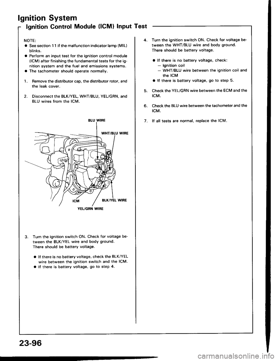
NOTE:
a See section I 1 if the malfunction indicator lamD (MlL)
blinks.
a Pertorm an input test for the ignition control module
(lCM) after finishing the fundamental tests for the ig-
nition system and the fuel and emissions systems.
a The tachometer should operate normally.
1. Remove the distributor cap, the distributor rotor, and
the leak cover.
2. Disconnect the BLK/YEL, WHT/BLU, YEL/GRN, and
BLU wires from the lCM.
3. Turn the ignition switch ON. Check for voltage be-
tween the BLK/YEL wire and body ground.
There should be battery voltage.
a lf there is no battery voltage, check the BLK^/EL
wire between the ignition switch and the lCM.
a lf there is battery voltage, go to step 4.
YEL/GRN wlRE
4.Turn the ignition switch ON. Check for voltage be-
tween the WHT/BLU wire and body ground.
There should be battery voltage.
a lf there is no battery voltage, check:- lgnition coil- WHT/BLU wire between the ignition coil and
the ICM
a lf there is battery voltage. go to step 5.
Check the YEL/GRN wire between the ECM and the
tcM.
Check the BLU wi.e between the tachometer and the
rcM.
It all tests are normal, replace the lCM.
6.
7.
23-96