Page 1103 of 1413
Condenser
Replacement
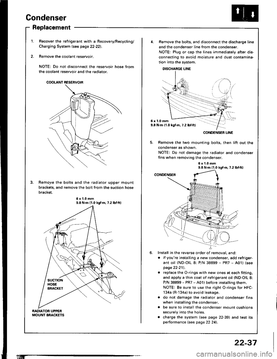
RAOIATOR UPPENMOUNT BRACKETS
Recover the relrigerant with a Becovery/Recycling/
Charging System (see page 22-221.
Remove the coolant reservoir,
NOTE: Do not disconnect the reservoir hose from
the coolant reservoir and the radiator.
COOLANT RESERVOIR
Remo.ve the bolts and the radiator upper mount
brackets, and remove the bolt from thg suction hose
bracket.
9.8 N.m {1.0 kgf.m.7.2 lbtftl
'1Iffi
22-37
6x1.0mm9.8 N.m (1.0 kgl.m,7.2 lbt.ft)
......-.....
CONOENSER LINE
Remove the bolts. and disconnect the discharge line
and the condenser line from the condenser.
NOTE: Plug or cap the lines immediately after dis-
connecting to avoid moisture and dust contamina-
tion into the system.
DISCHARGE LINE
Remove the two mounting bolts, then lift out the
condenser as shown.
NOTE: Do not damage the radiator and condenser
fins when removing the condenser.
6x1.0mm9.8 N.m (1.0 kgf.m, 7.2 lbl.tt)
Install in the reverse order of removal. and:
. if you're installing a new condenser, add refriger-
ant oil (ND-OIL 8: P/N 38899 - PR7 - A01) (see
page 22-21t,.
. replace the O-rings with new ones at each fitting,
and apply a thin coat of refrigerant oil {ND-OIL 8:
P/N 38899 - PR7 - A01) before installing them.
NOTE: Be sure to use the right O-rings for HFC-
134a (R-134a) to avoid leakage.
a do not damage the radiator and condenser fins
when installing the condenser,
. be sure to install the condenser mount cushions
securely into the holes.
. charge the system (see page 22-39) and test its
performance (see page 22 24!�.
Page 1104 of 1413
A/G System Service
Evacuation
Only use service equipment that is U.L.-listed and is cer-
tified to meet the roquirements of SAE J2210 to remove
HFC-134a (R-134a) lrom the 8ir conditioner system.
CAUTION: Exposulo to 6ir conditioner refligorrnt and
lubricani vapor or mi3t crn i.ritato 9y33, noaa and
thrort. Avoid bratthing ths .ir conditionor rsfrigorrnt
snd lubricsnt vtpor or mist.
lf accidental system discharge occurs, ventilate work
area before resuming service.
R-134a service equipment or vehicle 8ir conditioner sys-
tems should not be pressure tested or leak tested with
compressed ait.
!@ somo mixtuto3 ot ril and R'134! hav.
been shown to bo combustible at olevltad prossulo3
and can re3ult in fire or explosion crusing inlurY or
property damago, Navor us! comprossod air to prgsauro
test R-13/aa 3orvicr €quipmlnl or vohiclo air conditionol
sy3lems.
Additional health and safety information may be ob-
tained from the retrigerant and lubricant manufactures.
1. When an Ay'C System has been opened to the atmo-
sDhere, such as during installation or repair, it must
be evacuated using a R-134a refrigerant Recovery/
Recycling/Charging System. {lf the system has been
open for several days, the receiver/dryer should be
replaced.l
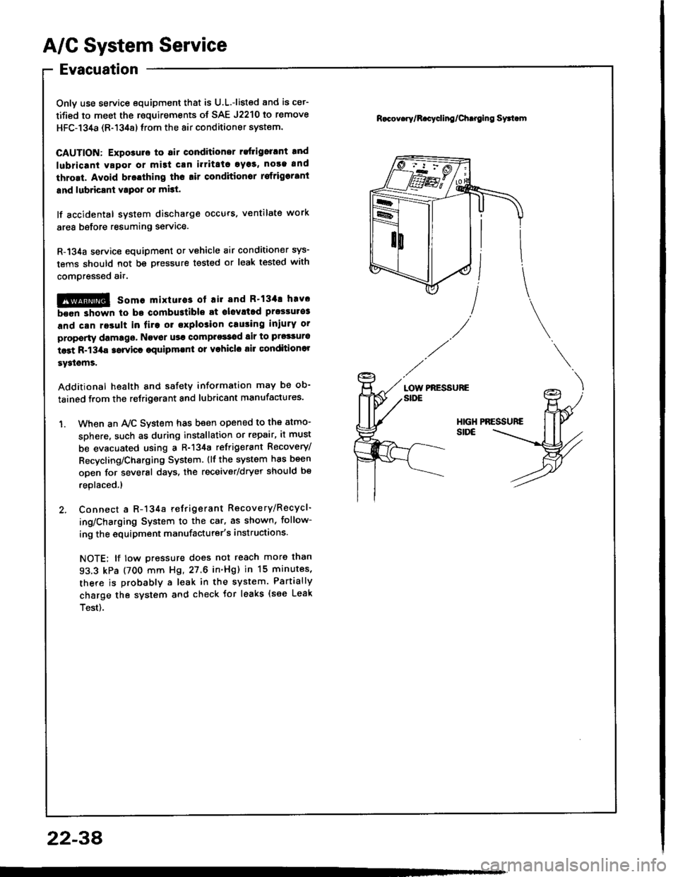
2. Connect a R-134a refrigerant Recovery/Recycl-
ing/Charging System to the car, as shown, follow-
ing the equipment manufacturer's instructions.
NOTE; lf tow pressure does not reach more than
93.3 kPa (700 mm Hg, 27.6 in'Hg) in 15 minutes,
there is probably a leak in the system. Partially
charge the system and check tor leaks {see Leak
Test).
R.cov.ry/R.cycling/Chtroing Syttom
PRESSUREaotnSIDE
2234
Page 1105 of 1413
Charging
Only use service equipment that is U.L.-listed and is cer-
tified to meet the requirements of SAE J2210 to remove
HFC-134a (R-134a) from the air conditioner svstsm.
CAUTION: Exporuro to rir conditionor .etrigorant and
lubric8nt yapor or misl can irritats cyos, no36 and
throlt. Avoid broathing tho lir conditionor rofrig6rant
lnd lubricant vlpor or mbt,
It accidental system discha.ge occurs, ventilate work
area before resuming service. Additional health and
safety information may be obtained from the refrigerant
and lubricant manufactures.
Rofrigerant capacity: f00:3n g (24.7:l,oz)
CAUTION: Do not ovorchlrgo thc syrtem; tho compr6s-
sor will be damagad.
Connect a R-134a refrigerant Recove.y/Recycling/
Charging System to the car, as shown, following the
equipment manufacturer's instructions.
R.cov.rylRccacling/Ch.rging Syrtom
22-39
Page 1106 of 1413
A/C System Service
Leak Test
Only use service equipment that is U.L.-listed and is cer-
tified to meet the requirements of SAE J2210 to remove
HFC-134a (R-134a) from the air conditioner system.
CAUTION: Exposura to air condition ratrigerant and
lubaicant vapor or mist can irritato oyes. nose and
throat. Avoid br€athing tho sir conditionsr reftigolant
and lubricant vapor or mist.
lf accidental svstem discharge occurs, ventilate work
area before resuming service.
R-134a service equipment or vehicle air conditioner sys-
tems should not be pressure tested or leak tested with
comoressed air.
@ some mixturos ot air and R'13'la have
b.6n shown to b€ combustible at glsvated pressur€s
and can result in firo or sxplo3ion causing iniury or
proporty damage. Ngvar uso compress€d tir to pro33ure
tost R-134a $rvics oquipmont or vohicl€ air Gonditionsr
systcms.
Additional health and satetY information may be ob-
tained from the refrigerant and lubricant manufactures'
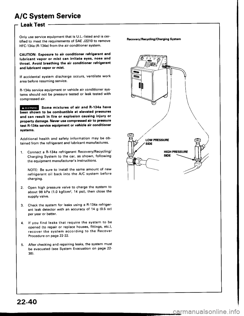
1. Connect a R-134a retrigerant Recovery/Recycling/
Charging System to the car. as shown, following
the equipment manufacturer's instructions.
NOTE: Be sure to install the same amount of new
refrigerant oil back into the A/C system before
chargtng.
2. Open high pressure valve to charge the system to
about 98 kPa (1.0 kgf/cm'�, 14 psi), then close the
supply valve.
3. Check the system for leaks using a R-134a refriger-
ant leak detector with an accuracy of '!4 g {0.5 oz)
per year or better.
4. lf you find leaks that require the system to be
opened (to repair or replace houses, fittings, etc.),
recover the system according to the Recover
Procedure on page 22-22.
5. Aiter checking and repairing leaks, the system must
be evacuated (see System Evacuation gn page 22-
38).
Rocov.ry/R.cycling/Ch.tging Sy3tcm
LOW PRESSURESIDE
HIGHSIDE
22-40
Page 1204 of 1413
Charging System
Component Location lndex
UI{DER.HOOD FUSE/BELAY BOX(USA: Has builr-in ELECTRICALLOAD DETECTOR {ELD) UNIT)Troubleshooting ot ELD, s€ction 11
BATTERYTost,
CHARGING SYSTEM LIGHTlln the gauge sssemblylT€st. pages 23-1OO. 101Bulb Locations, page 23-1 1 5
ALTERNATOR BELTInspoction and Adiustment, page 23-108
Alt6rnator/RegulatorTosl, pag€s 23-102, 1O3Replacament. page 23-'l 04Ovsrhaul, pago 23-105
23-98
Page 1206 of 1413
Charging System
Troubleshooting
Bofore troubleshooting check- tightness of the alternator belt (see page 23-1Og).- that the malfunction indicator tamp lMlL) of the ECM does not blink. lf it blinks, refer to section 1 1.
lf the charging system light is on, or th€ battery is dead or low, p€rtorm the following tests in the order listed below:
1. Baftery Test (see page 23-66)
2. Charging System Light Test
3. Alternator/RegulatorTest
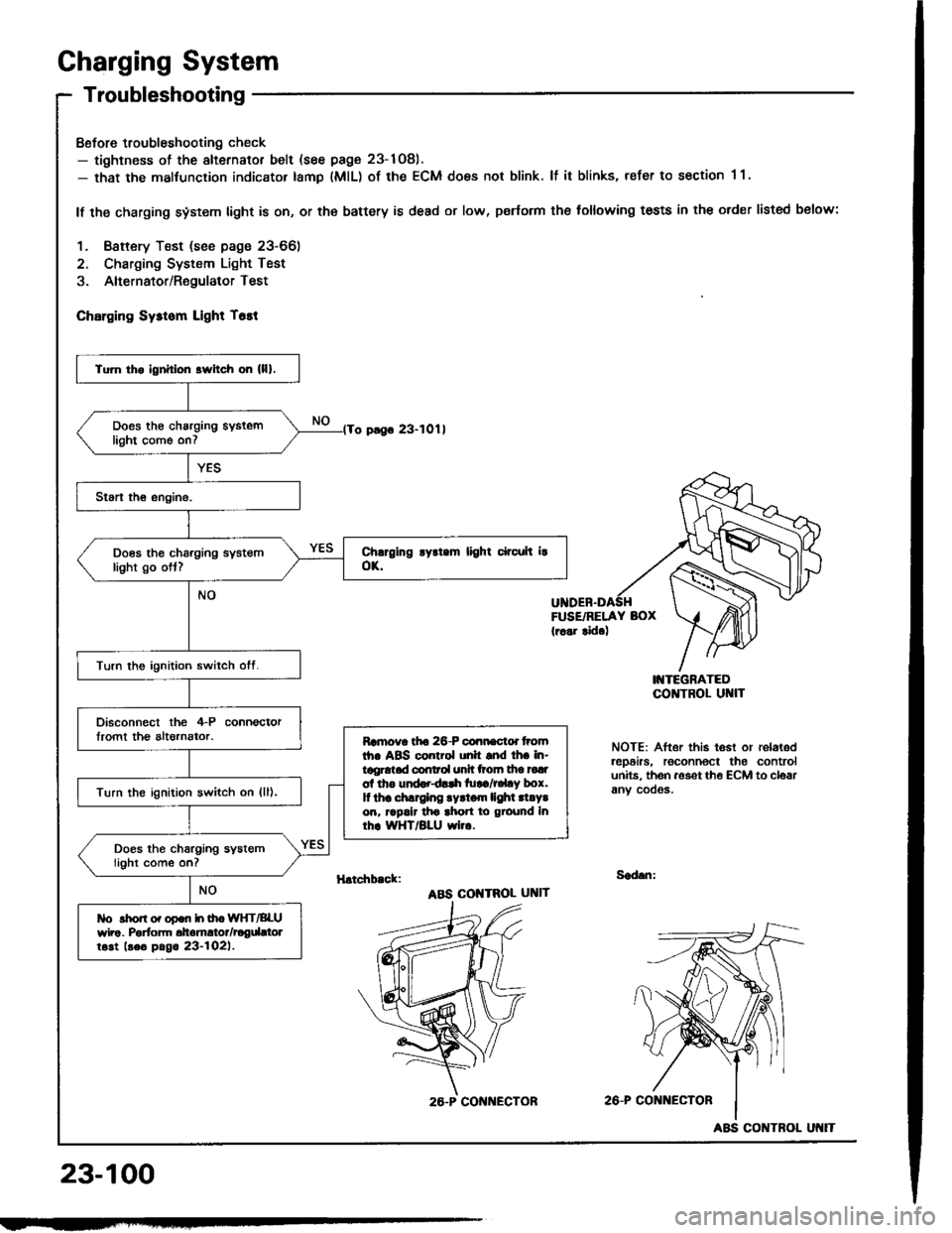
ChErging Sysrom Light T6tt
o pago 23-1011
FUSE/RELAY BOX(r..r tid.)
I'{TEGRATEDCO]TTROL UI{IT
NOTE: After this test or relaledrep6irs, roconnoct the controlunits. th6n aoset th€ ECM to cloarany cooos.
H.tchb.ck:Sad.n:
ABS COI{TROL UNIT
2A-P CONi{ECTOR
23-100
Tu]n tho ignhlon srvitch on (lll.
Does th€ charging syslemlight come on7
Does tho charging systemlight go ott?
Turn the ignition switch otf.
Disconnect the 4-P connoctorlromt th€ altornator.Ramova tfto 26-P connactd tromth. ABS control unh snd lh. in-tggrotad conrol unh ttoln tha tadol tho und..dlrh tu!a/r.l.y box.It thr .hlrglng .yrtom lighl .l.Y.on, rrpalr tho ahon to ground Inrhr WHT/BLU wi...
Turn the ignition switch on {ll),
Does the charging systemlight come on?
tlo rhon o. opon h ih. WIfT/BLUwho. Porfom dtomrtor/rogdttolrost beo pag. 23-l02l.
26.P CON ECTOR
ABS CONTROL
Page 1207 of 1413
lFrom page 23-10O)'No. 24 (15 A): 818B'lNo. 24 (20 A): 818C1ongrneengine
Turn the ignition switch ott.
Check fuse *No. 24 in the under-dash tuse/relay bor.
Disconnect the 4-P connectorIrom the alternator.
Turn the ignition switch on {ll).
Ch6ck forvoltago between tho lGterminal (BLK/YEL wire) of rho il-Pconnector and body ground.
ls there battery voltage?Rgp.i. op.n in th. BLK|'EL wiro.
Ground the WHT/BLU wire at theL terminal ot the 4-P connector.
Chock for ! blown chrrging ry3-rom llghr bulb. It rh. butb i! oK,ropair open in lho IiYHT/BLU wiro.
Does the charging system lightcome on?
wirg sideL IWHT/BLUI
(cont'd)
23-101
Page 1208 of 1413
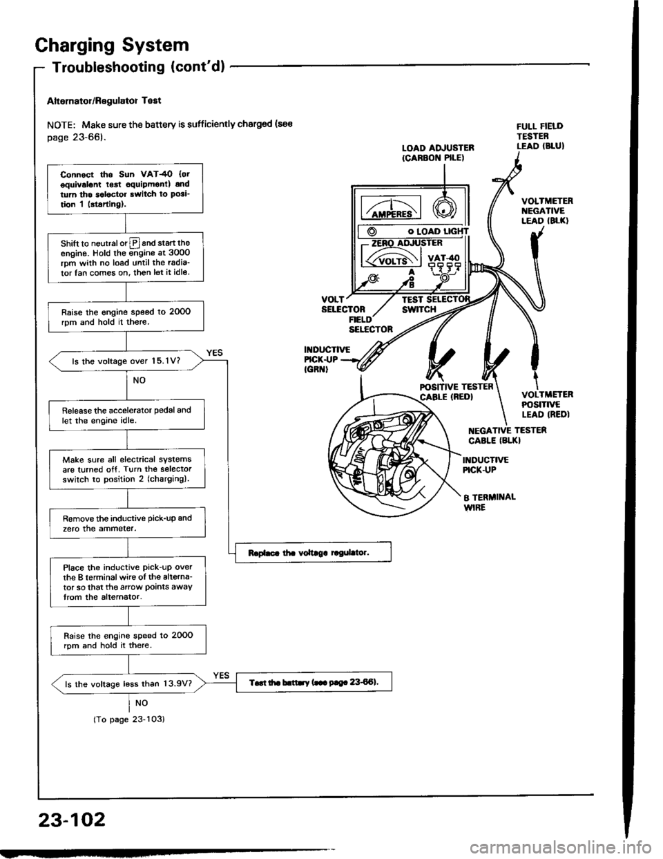
Charging System
Altornator/Regulator Test
NOTE; Mske sure the battery is sufficiently chargod (sa€
page 23-66).
NO
tropagezJ-ruJ,
O IOAD
VOLTTESTSELECTONswlTcH
II{DUCTIVE
FULL FIELDTESTEBLEAD (BLUILOAD ADJUSTERICARBON PILE)
FICK.I.|PIGR '
VOLTMETERt{EGATIVELEAD (8LK}
VOLTMETERPOStTtVELEAD IREDI
EGATIVE TESTER
CABLE (BLKI
INDUCTIVEPICK.UP
B TERMI]TALWIRE
23-102
Connoct tho Sun VAT4O {otooulvslont lgrt equipmonl) andtum tho s6l6ctor rwitch ro posi_
tion I |rtarting).
shift to neurralorlPland start theengino. Hold the ;;gine at 3oO0rpm wiih no load until the radia_
tor lan com€s on. then let it idle.
Raise the engine speed to 2OOOrom and hold il there.
ls lhe voltage over 15.1V?
Release the accelerator pedal andlet the engino idle.
Make sure all electrical systemsare turned otf. Turn the selectorswilch to position 2 (charging).
Remove the inductive pick-up and
zero the ammeter.
Place the inductive pick-uP overthe B terminalwire oI the altgrna-tor so that the arow Doints awaytrom the alternator.
Raise the engins speed lo 20OOrpm and hold it there.
T..t itr b.ttry (.- 9|e. 8€Al.ls the voltage less than 13.9V?