1994 HONDA INTEGRA battery replacement
[x] Cancel search: battery replacementPage 1210 of 1413
Charging System
Alternator Replacement
NOTE: The original radio has a coded theft protection
circuit. Be sure to get the customer's code number before
- disconnecting the battery.- removing the No. 32 {7.5 A) fuse from the under-hood
fuse/relay box.- removing the radio.
After service, reconnect powet to the radio and turn it on.
When the word "CODE" is displayed, enler the cus-
tomer's 5-digit code to restore radio operation.
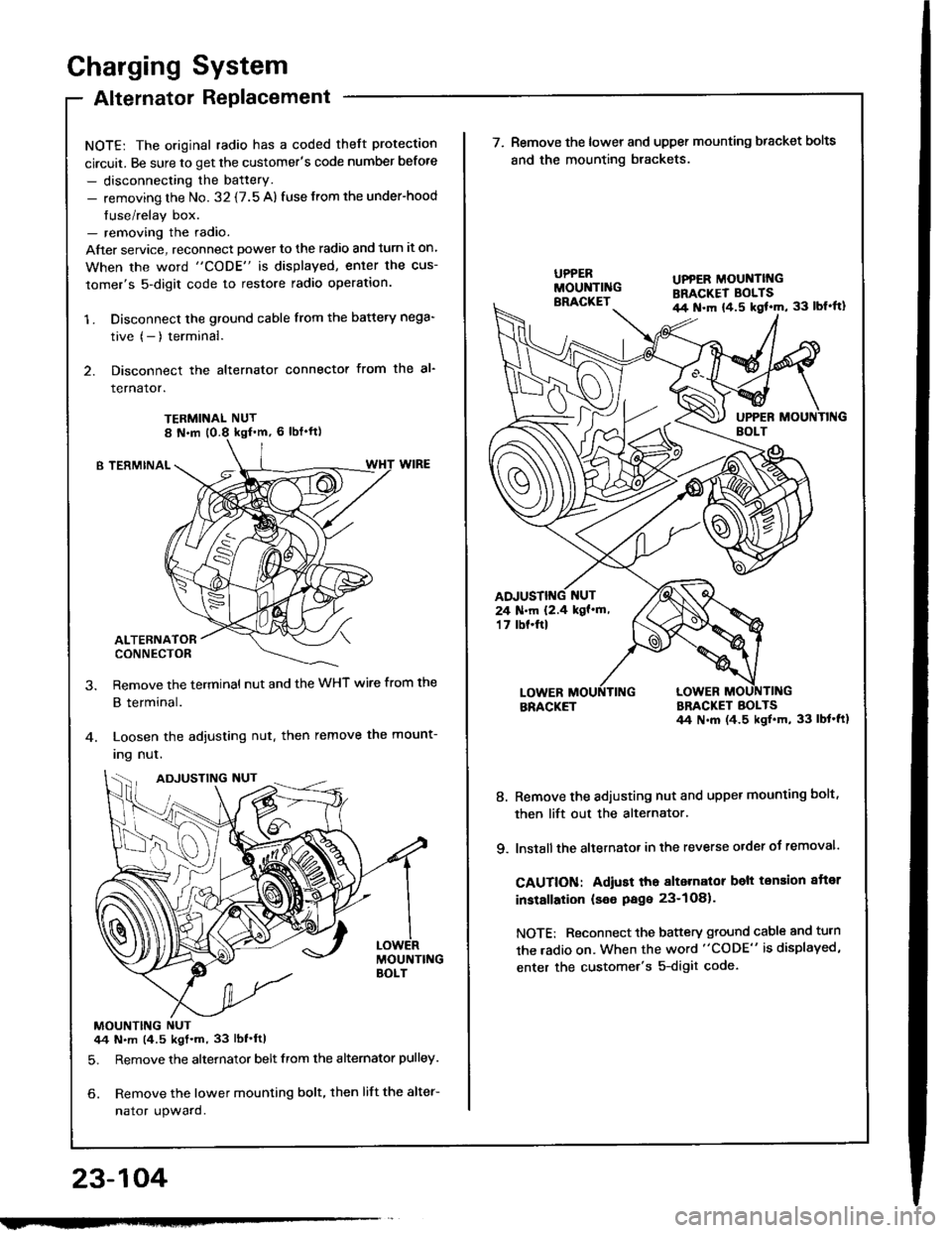
1 . Disconnect the ground cable from the battery nega-
tive (- ) terminal.
2. Disconnect the alternator connector from the al-
rernaror.
TERMINAL NUT
B TERMINAL
ALTERNATORCONNECTOR
Remove the terminal nut and the WHT wire from the
B terminal.
Loosen the adjusting nut. then remove the mount-
Ing nul.
MOUNTING NUT44 N.m (4.5 kgt.m, 33 lbf'ftl
5. Remove the alternator belt from the alternator pulley.
6. Remove the lower mounting bolt, then lift the alter-
nator upward.
23-104
ADJUSTING NUT
w
UPPER MOUNTII{GBRACKET BOLTSil4 N.m {4.5 kgl'm, 33 lbl'ft}
24 N.m 12.4 kgf'm,'t 7 tbf.ftl
\ (^,-(\
\-/ I
7. Remove the lower and upper mounting bracket bolts
and the mounting brackets.
BRACKETBRACKET BOLTS44 N.m (4.5 ksl.m, 33 lbt'ft1
8. Remove the adiusting nut and upper mounting bolt,
then lift out the alternator.
9. lnstall the altetnator in the reverse order of removal.
CAUTION: Adiust tho alternalor belt tension aftor
installation (seo Page 23-1O81.
NOTE: Reconnect the battery ground cable and turn
the radio on. When the word "CODE" is displayed,
enter the customer's 5-digit code.
Page 1249 of 1413
Shift Lock Solenoid Test/Replacement
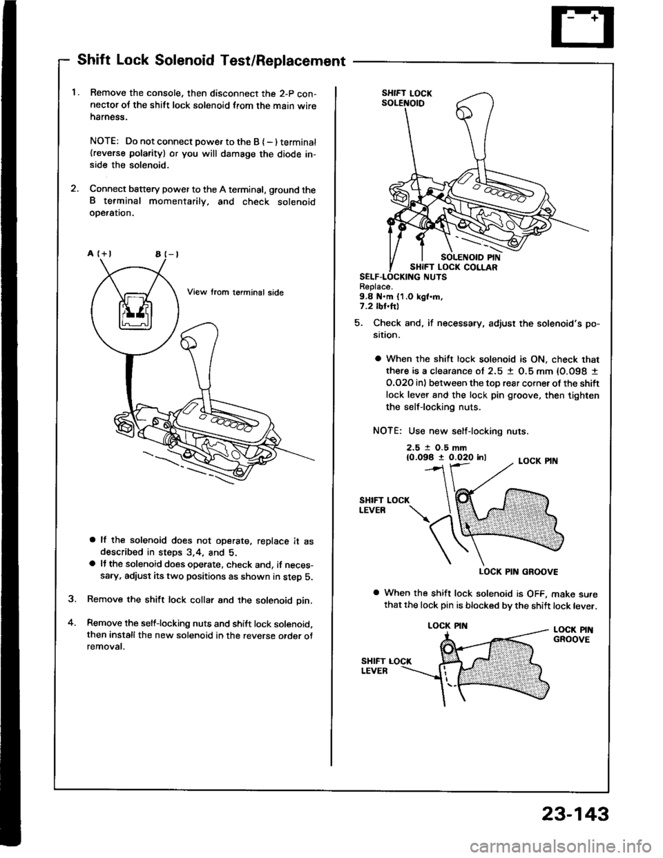
Remove the console, then disconnect the 2-p con-neclor oJ the shift lock solenoid from the main wireharness.
NOTE: Do not connect powe. to the B { - ) terminat(reverse polarity) or you will damsge the diode in-side the solenoid.
Connect battery power to the A terminal, ground theB terminal momentarily. and check solenoidoDeralron.
a lf the solenoid does not operate, replace it asdescribed in steps 3,4, and 5.a lJ the solenoid does operate, check and, if neces-sary, adiust its two positions as shown in step 5.
Remove the shift lock collar and the solenoid pin.
Remove the selflocking nuts and shift lock solenoid,then installthe new solenoid in the reverse otder otremovat.
a
Replace.9,8 N.m {1.0 kgl.m,7.2 tbl.hl
5. Check and, if necessary, adjust the solenoid's po-
sition.
a When the shift lock solenoid is ON, check that
there is a clearance ol 2.5 1 O.5 mm {O.O98 I
O.O2O in) between the toD rear corner ot the shift
lock lever 8nd the lock pin groove, then tighten
the selflocking nuts.
NOTE: Use new self-locking nuts.
2.5 t O.5 mm{0.098 t 0.020 inl
SHIFTLEVEB
LOCK PIN GROOVE
a When the shift lock solenoid is OFF, make surethat the lock pin is blocked bv the shift lock lever.
LOCK PINGROOVE
LOCK
LOCK PIN
23-143
Page 1294 of 1413
Stereo Sound System
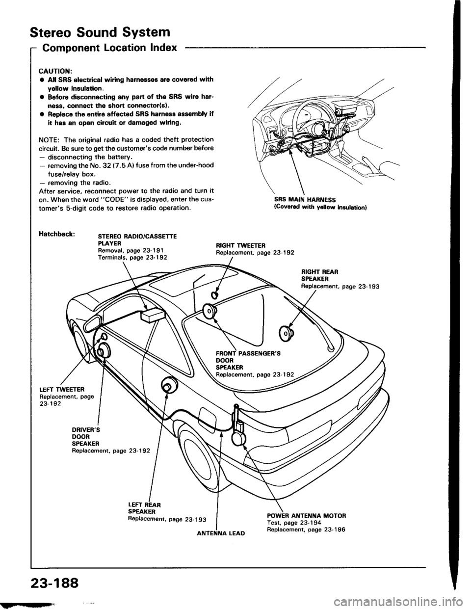
Component Location Index
LEFT TWEETERReplacement, page
23-192
DRIVER'SDOORSPEAKERRepfacement, page 23-192
CAUTION:
a All SRS el€ctrical wlring harneaseE are covered with
yallow insulation.
a Belore dbconnscting any part of the SRS wire har-
nass, connect tho short connector(sl.
a Replace tho entir6 affoctod SRS harn6ss assembly if
it has an opan circuit or damag6d widng.
NOTE: The original radio has a coded theft protection
circuit. Be sure to get the customet's code number belore- disconnecting the battery.- removing th€ No. 32 (7.5 A)tuse from the under-hood
fuse/relay box.- removing the radio.
After service, reconn€ct power to th€ radio and tutn it
on. When the word "CODE" is displaved, enter the cus-
tomer's 5-digit code to restore radio opelation.
Hatchback:STEBEO RADIO/CASSETTEPTAYERRemoval. paoe 23-191Terminals, page 23-192
SBS MAII{ I{ARI{ESS(Covor€d wirh y6llow in3ulationl
LEFTSPEAKER
RIGHT REARSPEAKERReplacement. page 23-193
ANTENNA MOTORTest, page 23-194
DOORSPEAKERRepfacement, page 23-192
23-188
!iltil;s'
Replacemenr. page 23-193
Replacement, page 23-196
Page 1354 of 1413
Cruise Gontrol
Set/Resume Switch Test/Replacement
CAUTION:
a All SRS ol6ct cal widng herne$a3 err covorod with
y6llow insulation.
a Bototo disconnecting any part ot tho SRS wiro h8r-
n6sa, connoct tho ghort connector(sl,
a Rsplaco the antire aftected SRS harness arsombly if
it has an op6n chcuit or damagod wiring.
NOTE: The original radio has a coded theft protection
circuit, Be sure to get the customer's code number befor€- disconnecting the battery.- removing the No. 32 (7.5 A) fuse from the under-hood
fuse/relay box.- removing the radio.
Afte, service, reconnect power to the radio and turn it
on. When the word "CODE" is displayed, enter the cus-
tomer's s-digit code to restore radio op€ration.
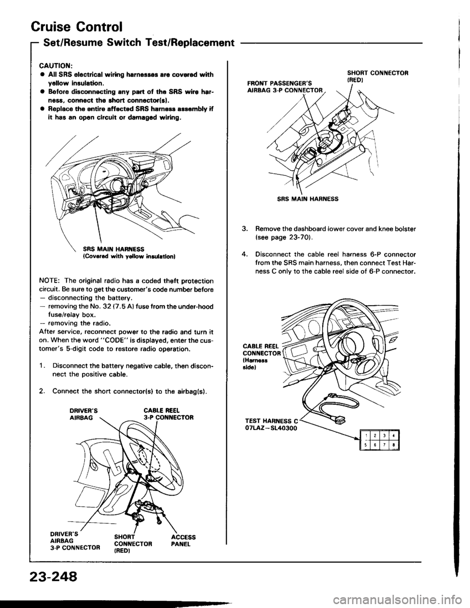
1 . Disconnect the battery negative cable, then discon-
nect the Dositive cable.
2. Connect the short connector(s) to the airbag(s).
DRIVER'SAIRBAG3-P CONNECTOR
SHORT ACCESSCON]TECTON PANEL(REDI
23-248
SRS MAIN HARNESS
3. Remove the dashboard lower cover and knee bolster(see page 23-70).
4. Oisconnect the cable reel harness 6-P connector
from the SRS main harness, then connect Test Har-
ness C onlv to the cable reel side of 6-P connector.
CABLE REELCONNECTORlHlrnoa!Eidol
Page 1369 of 1413
l.
2.
1.
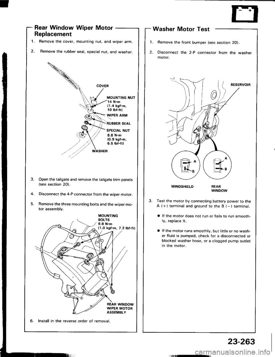
Rear Window Wiper Motor
Replacement
Remove the cover, mounting nut, and wiper arm.
Remove the rubber seal, special nut, and washer.
MOUNTING NUT
Washer Motor Test
Remove the front bumper (see section 20).
Disconnect the 2-P connector lrom the washer
motor.
RESERVOIR
WINDSHIELD
14 N.m11.4 kgf.m,10 tbt.trl
WIPER ARM
RUBBER SEAL
SPECIAL NUT
8.8 N.m{0.9 kgt'n,6.5 rbt.fr)
MOUNTINGBOLTS9.8 N.m(1.O kgf.m, 7.2 lbf.ttl
-4
)
Open the tailgate and remove the tailgate trim panels(see section 20).
Disconnect the 4-P connector from the wiper motor.
Remove the three mounting bolts and the wiper mo-
tor assembly.
REARwrNDow
Test the motor by connecting battery power to the
A ( + ) terminal and ground to the B (- ) terminal.
a ll the motor does not run or fails to run smooth-
ly, replace it.
a lf the motor runs smoothly, but little or no wash-
er fluid is pumped. check for a disconnected orblocked washer hose, or a clogged pump outlet
in the motor.
6, Install in the reverse order o{ removal.
23-263
Page 1376 of 1413
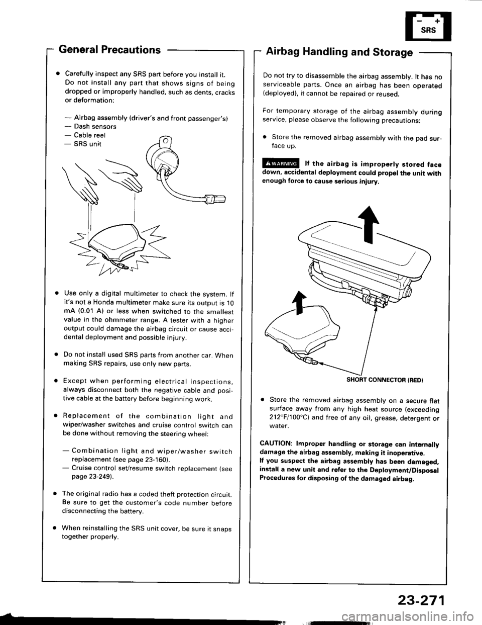
- Dash sensors- Cable reel- SRS unit
General Precautions
Carefully inspect any SRS part before you install it.Do not install any part that shows signs of beingdropped or improperly handled, such as dents, cracksor deformation:
- Airbag assembly {driver's and front passenger's)
Airbag Handling and Storage
Do not try to disassemble the airbag assembly. lt has noserviceable parts. Once an airbag has been operated(deployed), it cannot be repaired or reuseo.
For temporary storage of the airbag assembly duringservice, please observe the following precautions:
. Store the removed airbag assembly with the pad sur-face up.
!@ It the airbag is impropsrty stored facsdown, accidental deployment could propel the unit withenough force to cause setious iniury
Store the removed airbag assembly on a secure flatsufface away from any high heat source (exceeding
212"Fl1OO'Cl and free of any oil. grease, detergent or
CAUTION: lmproper handling or storage can internallydamage the airbag assembly, making it inoperativ€.ll you suspect the airbag assembly has been damagod,install a new unit and rgler to the Deployment/DigposalProcedures lor disposing of the dsmaged airbag.
Use only a digital multimeter to check the system. lfit's not a Honda multimeter make sure its output is 10mA (0.01 A) or less when switched to the smallestvalue in the ohmmeter range. A tester with a higheroutput could damage the airbag circuit or cause accidental deployment and possible injury.
Do not install used SRS parts from another car. Whenmaking SRS repai.s, use only new pans.
Except when performing electrical inspections,always disconnect both the negative cable and posi-
tive cable at the battery before beginning work.
Replacement of the combination light andwiper/washer switches and cruise control switch canbe done without removing the steering wheell
- Combination light and wiper/washer switchreplacement (see page 23-160).- Cruise control sevresume switch replacement {seepage 23-2491 .
The original radio has a coded theft protection circuit.Be sure to get the customer's code number beforedisconnecting the battery.
When reinstalling the SRS unit cover, be sure it snapstogether properly.
SHORT CONNECTON {REDI
23-271
Page 1400 of 1413
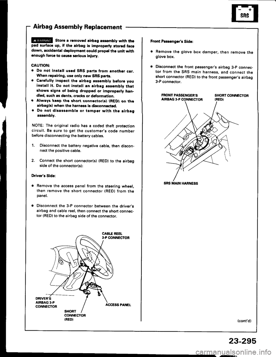
Airbag Assembly Replacement
@E storc a r.movcd lirb.g rslombty with thcp.d surfaco up, if tho lirbrg is improparly 3iorad frcadown, accidontal d.ploymert could plopcl tha unit withcnough torcr lo causc lariour iniury.
CAUTION:
. Do not inst.ll urld SRS plrts trom lnothar c!1,Whon lepairing, uss only now SRS prrt!.o Carefully inlpcct thc airblg rlrcmbly bltorc you
install it. Do not inst.ll an airbag !$.mbly thrt3how! sign3 of bcing droppcd or improparly hrn-dlod, such as dont!. crack3 or dstormation.. Alwry! koop ths rhort connactor(3l (REDI on thaairbrg{s} whon tho hsrnca3 i! dirconnastld.. Do not diras3ombl! or tamp€l with tha lirbrga$ombly.
NOTE: The original radio has a coded th6ft protection
circuit. Be sure to get the customer's code number
before disconnecting the battery cables.
1. Oisconnect the battery nogative cabl6, then discon-nect the positive cable.
2. Connect the short connecto(s) (R€D) to the aifbagside of the connector(s);
Drivo/s Sido:
a Remove the access panel from the steering whesl,
then ramove the short connector (REDI from th6paner.
. Disconnect the 3-P connector betwesn the driv6r'sairbag and cable reel, then connect th6 short connec-
tor {RED} to the airbag side of the connector.
Fror{ P$!.ngar/3 Sida:
. Remove th6 glove box damper, then remove theglove box.
. Disconnoct the front psssenger's airbag 3-p connec-tor from the SRS main harness, and connect theshort connoctor (RED) to the front passenger,s airbag3-P connector.
FROIVTPASS€NGEF'S SHOBTOONNECTORAIRBAG 3.P CONNECTOR (REDI
(cont'd)
23-295
,ry!$,
Page 1403 of 1413
Supplemental Restraint System (SRSI
Airbag Assembly Replacement (cont'd)
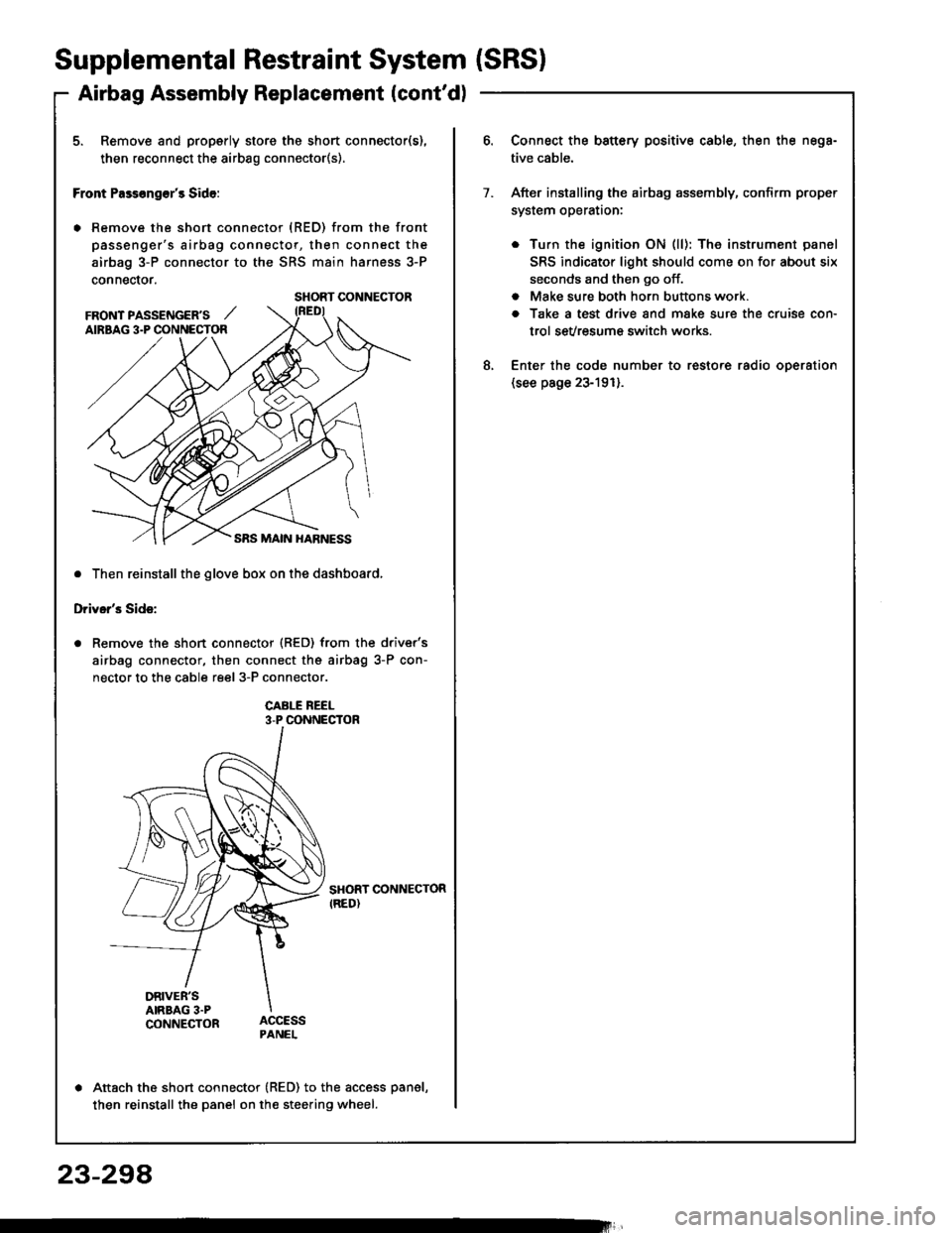
5. Remove and properly store the short connector(s),
then reconnect the airbag connector(s).
Front Pass€ng€r's Side:
. Remove the short connector (RED) from the front
passenger's airbag connector, then connect the
airbag 3-P connector to the SRS main harness 3-P
connector.
. Then reinstall the glove box on the dashboard,
Driver's Side:
Remove the short connector (RED) from the driver's
airbag connector, then connect the airbag 3-P con-
nector to the cable reel 3-P connector.
CABI-E REEL3-P CONNECTOR
SHORT CONNECTORIRED)
DRIVER'SAIRBAG 3.PCONNECTOR
Attach the short connector (RED) to the access panel,
then reinstall the panel on the steering wheel.
SHORT CONNECTOR
FRONT PASSENGER'S ,,'AIRBAG 3.P CONNECTOR
Connect the battery positive cable, then the nega-
tive cable.
After installing the airbag assembly, confirm proper
system operataon:
. Turn the ignition ON (ll): The instrument panel
SRS indicator light should come on for about six
seconds and then go off.
. Make sure both horn buttons work.
a Take a test drive and make sure the cruise con-
trol sevresum€ switch works.
Enter the code number to restore radio oDeration(see page 23-191).
7.
8.
23-294