Page 1109 of 1413

Troubleshooting
Tips and Precautions
Before Troubloshooting
a Check applicable fuses in the appropriate fuse/relay
DOX.
a Check the battery for damage, state of charge, and
clean and tight connections.a Check the alternator belt tension.
CAUTION:
a Do not quick-charg€ a battery unless the batteryground cabla has be€n disconnoctsd. oth€rwisoyou will damage the alternator diodss.a Do not att6mpt to crank the engine with the bat-tery ground cable loosely connectsd or you will se-vorsly damag€ tho widng.
a The original radio has a codod thatt plotection ci.-cuit. Be sul€ to got tho customor's code numbet
before- disconnecting th€ battery.- lomoving tho No. 32 (7.5 Al tuso f.om the
under-hood tuse/lelay box.- removing tho radio.
Aflor s€lvic€. reconn€ct powet to tho radio and
turn it on. Whon the word "CODE" is displayed,
€nt€l the customer'E s-digit codo to .astore ladio
operation.
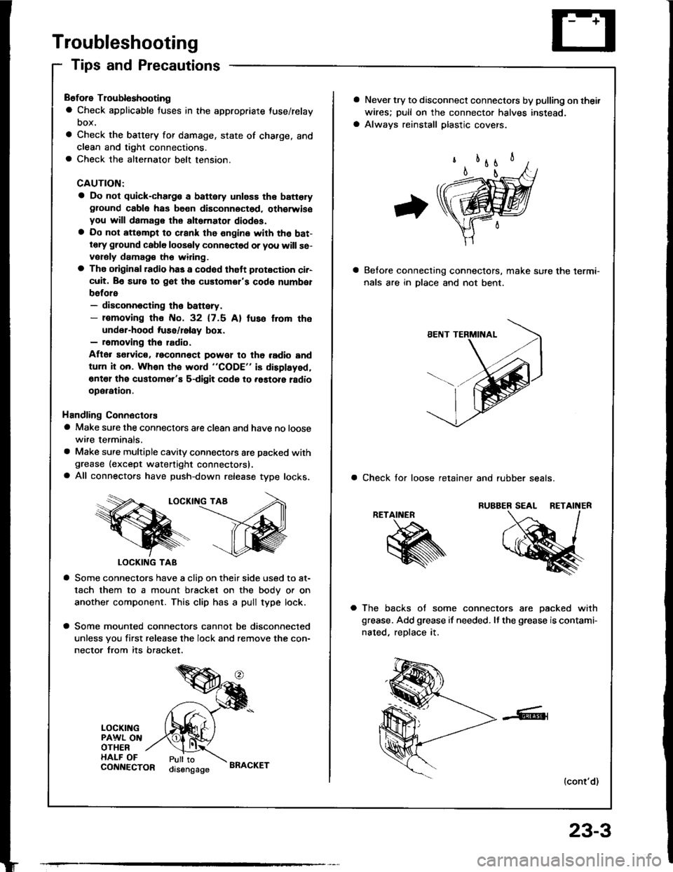
Handling Connectors
a Make sure the connectors are clean and have no loose
wire terminals.
a Make sure multiple cavity connectots are packed withgrease (except watertight connectors).a All connectors have push-down release type locks.
LOCKII{G TAA
LOCKING TAB
a Some connectors have a clio on their side used to at-
tach them to a mount bracket on the body or on
another component. This clip has a pull type lock.
a Some mounted connectors cannot be disconnected
unless you first release the lock and remove the con-
nector from its bracket.
LOCKINGPAWL ONOTHERHALF OFPull toorsengageCONNECTORBRACKET
23-3
a Never try to disconnect connectors by pulling on thei.
wires; pull on the connector halves instead.
a Always reinstall plastic covers.
Belore connecting connectors, make sure the lermi-
nals are in Dlace and not bent.
a Check tor loose retainer and rubber seals.
RETAINER
a The backs of some connectors are oacked with
grease. Add grease if needed. It the grease is contami-
nated, reDlace it.
(cont'd)
Page 1204 of 1413
Charging System
Component Location lndex
UI{DER.HOOD FUSE/BELAY BOX(USA: Has builr-in ELECTRICALLOAD DETECTOR {ELD) UNIT)Troubleshooting ot ELD, s€ction 11
BATTERYTost,
CHARGING SYSTEM LIGHTlln the gauge sssemblylT€st. pages 23-1OO. 101Bulb Locations, page 23-1 1 5
ALTERNATOR BELTInspoction and Adiustment, page 23-108
Alt6rnator/RegulatorTosl, pag€s 23-102, 1O3Replacament. page 23-'l 04Ovsrhaul, pago 23-105
23-98
Page 1206 of 1413

Charging System
Troubleshooting
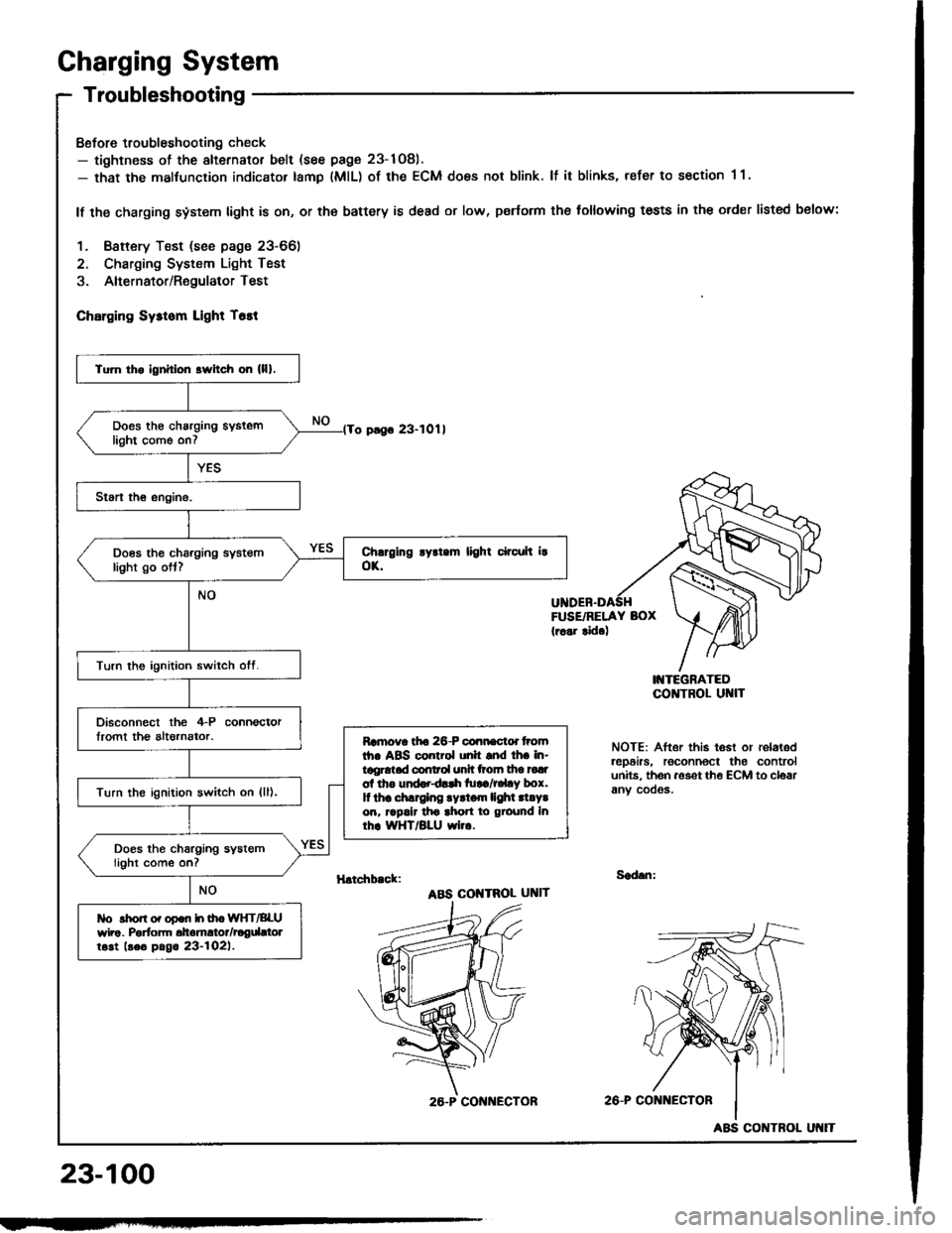
Bofore troubleshooting check- tightness of the alternator belt (see page 23-1Og).- that the malfunction indicator tamp lMlL) of the ECM does not blink. lf it blinks, refer to section 1 1.
lf the charging system light is on, or th€ battery is dead or low, p€rtorm the following tests in the order listed below:
1. Baftery Test (see page 23-66)
2. Charging System Light Test
3. Alternator/RegulatorTest
ChErging Sysrom Light T6tt
o pago 23-1011
FUSE/RELAY BOX(r..r tid.)
I'{TEGRATEDCO]TTROL UI{IT
NOTE: After this test or relaledrep6irs, roconnoct the controlunits. th6n aoset th€ ECM to cloarany cooos.
H.tchb.ck:Sad.n:
ABS COI{TROL UNIT
2A-P CONi{ECTOR
23-100
Tu]n tho ignhlon srvitch on (lll.
Does th€ charging syslemlight come on7
Does tho charging systemlight go ott?
Turn the ignition switch otf.
Disconnect the 4-P connoctorlromt th€ altornator.Ramova tfto 26-P connactd tromth. ABS control unh snd lh. in-tggrotad conrol unh ttoln tha tadol tho und..dlrh tu!a/r.l.y box.It thr .hlrglng .yrtom lighl .l.Y.on, rrpalr tho ahon to ground Inrhr WHT/BLU wi...
Turn the ignition switch on {ll),
Does the charging systemlight come on?
tlo rhon o. opon h ih. WIfT/BLUwho. Porfom dtomrtor/rogdttolrost beo pag. 23-l02l.
26.P CON ECTOR
ABS CONTROL
Page 1210 of 1413

Charging System
Alternator Replacement
NOTE: The original radio has a coded theft protection
circuit. Be sure to get the customer's code number before
- disconnecting the battery.- removing the No. 32 {7.5 A) fuse from the under-hood
fuse/relay box.- removing the radio.
After service, reconnect powet to the radio and turn it on.
When the word "CODE" is displayed, enler the cus-
tomer's 5-digit code to restore radio operation.
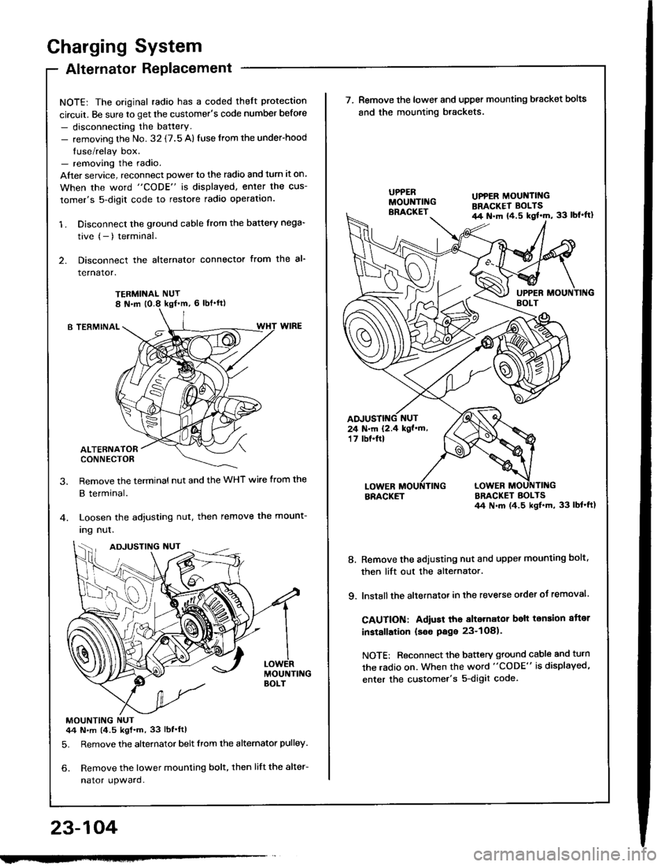
1 . Disconnect the ground cable from the battery nega-
tive (- ) terminal.
2. Disconnect the alternator connector from the al-
rernaror.
TERMINAL NUT
B TERMINAL
ALTERNATORCONNECTOR
Remove the terminal nut and the WHT wire from the
B terminal.
Loosen the adjusting nut. then remove the mount-
Ing nul.
MOUNTING NUT44 N.m (4.5 kgt.m, 33 lbf'ftl
5. Remove the alternator belt from the alternator pulley.
6. Remove the lower mounting bolt, then lift the alter-
nator upward.
23-104
ADJUSTING NUT
w
UPPER MOUNTII{GBRACKET BOLTSil4 N.m {4.5 kgl'm, 33 lbl'ft}
24 N.m 12.4 kgf'm,'t 7 tbf.ftl
\ (^,-(\
\-/ I
7. Remove the lower and upper mounting bracket bolts
and the mounting brackets.
BRACKETBRACKET BOLTS44 N.m (4.5 ksl.m, 33 lbt'ft1
8. Remove the adiusting nut and upper mounting bolt,
then lift out the alternator.
9. lnstall the altetnator in the reverse order of removal.
CAUTION: Adiust tho alternalor belt tension aftor
installation (seo Page 23-1O81.
NOTE: Reconnect the battery ground cable and turn
the radio on. When the word "CODE" is displayed,
enter the customer's 5-digit code.
Page 1214 of 1413

Charging System
Alternator Belt Inspection and Adjustment
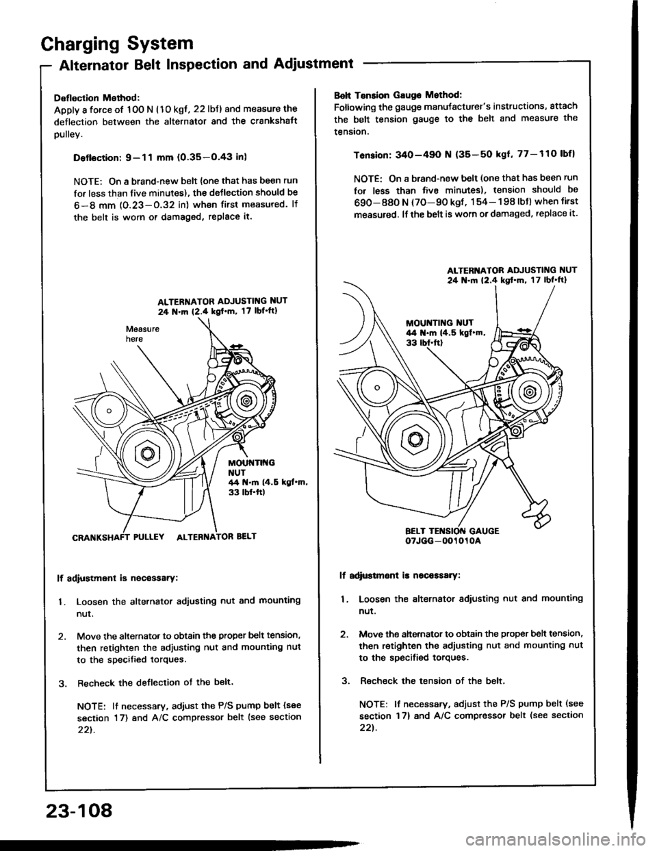
Deflection Method:
Apply a force of 100 N (1o kgt, 22 lbJ) and measure the
deflection between the alternator and the crankshatt
pulley.
Detlsction:9-11 mm (0.35-O.43 inl
NOTE; On a brand-new belt {one that has be€n run
for less than five minutes), the deJlection should be
6-8 mm 1O.23-O.32 in) wh€n first measured. lf
the belt is worn or damaged, replace it.
ALTER'{ATOR ADJUSTIT{G NUT
24 N.m {2.4 kgl'm, 17 lbl'ft1
MOUt{Tlt{GNUT44 t{.m (4.5 kgt.m,33 tbf.ft)
PULLEY ALTEBNA
lf adiustment is nocessarY:
1. Loosen the alternator adjusting nut and mounting
nur.
2. Move the alternator to obtain the proper belt tension,
then retighten the adjusting nut and mounting nut
to the specified torques.
3. Recheck the deflection ot the belt.
NOTE: lt necessary, adiust the P/S pump belt (see
section 17) and A/C compressor belt lsee section
22t.
23-108
Boh Tsnsion Gaug6 Mothod:
Foltowing the gauge manuJacturer's instructions, attach
the belt tension gauge to the belt and measure the
tension.
Tension: 340-49O N (35-50 kgl, 77-110 lbfl
NOTE: On a brand-new belt (one that has been run
for less than tive minutes), tension should be
690-880 N (70-90 kgt, 154- 198 lbJ) when tirst
measured. lf the belt is worn or damaged, replace it.
lf adi$tmsnt is nscaasary:
1. Loosen the alternator adiusting nut and mounting
nut.
2. Move ths ahernator to obtain the proper bslt tension,
then retighten the adjusting nut and mounting nut
to the specified torques.
3. Recheck the tension of the belt,
NOTE: lf necessary, adjust the P/S pump belt (see
section 17) and A/C compressor belt (see section
22t.
ALTERI{ATOR ADJUSTING NUT
24 .ln 12.4 kst'm, 17lbl'ft}
oTJGG-0O1010A