Page 1369 of 1413

l.
2.
1.
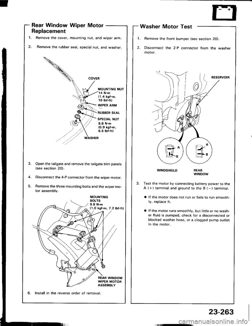
Rear Window Wiper Motor
Replacement
Remove the cover, mounting nut, and wiper arm.
Remove the rubber seal, special nut, and washer.
MOUNTING NUT
Washer Motor Test
Remove the front bumper (see section 20).
Disconnect the 2-P connector lrom the washer
motor.
RESERVOIR
WINDSHIELD
14 N.m11.4 kgf.m,10 tbt.trl
WIPER ARM
RUBBER SEAL
SPECIAL NUT
8.8 N.m{0.9 kgt'n,6.5 rbt.fr)
MOUNTINGBOLTS9.8 N.m(1.O kgf.m, 7.2 lbf.ttl
-4
)
Open the tailgate and remove the tailgate trim panels(see section 20).
Disconnect the 4-P connector from the wiper motor.
Remove the three mounting bolts and the wiper mo-
tor assembly.
REARwrNDow
Test the motor by connecting battery power to the
A ( + ) terminal and ground to the B (- ) terminal.
a ll the motor does not run or fails to run smooth-
ly, replace it.
a lf the motor runs smoothly, but little or no wash-
er fluid is pumped. check for a disconnected orblocked washer hose, or a clogged pump outlet
in the motor.
6, Install in the reverse order o{ removal.
23-263
Page 1370 of 1413
Wipers/Washers
Washer Replacement
1.
5.
6.
Bemove the Jront bumper (see section 2Ol.
Remove the left lront inner fender.
Disconnect the 2-P connector and hose from the
washer motor.
Remove the three mounting bohs and the washer
reservorr.
Remove the washer motor from the reservoir.
Remove the windshield wiper arms and air scoop
(see page 23-261). Then remove the washer noz-
zles and hoses.
lnstall in the reverse order of removal.
NOTE:
a Take care not to pinch the hoses during instal-
lation.
a Install the clips tirmly.
a After installing, adjust the aim of the washer
nozztes.
7.
REARwtt{DowWASHERt{ozzLEWINDSHIELDWASHERNOZZLE
n
V..,.,,@
l(H
n
MOUNTINGBOLTS9.8 N.m{1.O kgf.m, 7.2 lbf.ftl
23-264
Page 1371 of 1413
Supplemental Restraint System
(sRst
Gomponent Location Index .................. 23-266
Description ..23-267
Circuit Diagram 23-268
Wiring Locations 23-270
Precautions/Procedures ..23-271
Troubfeshooting ............. ..23-276
Airbag Assembly
Repfacement .................. 23-295
Disposal ....23-299
Cable Reel
Replacement .................. 23-301
Dash Sensor
Replacement .................. 23-305
SRS Unit
Replacement .................. 23-307
Page 1372 of 1413
Supplemental Restraint System (SRS)
Component Locirtion Index
UNDER.DASHFUSE/RELAY BOX
SRS INDICATOR LIGHT(ln th6 gaug6 assembly)Troubleshooting, page 23-276Gauge assembly, page 23-113
CABLE REELReplacement,page 23-301
AIRBAGBeplacement, page 23.295
SRS UNIT (lncluding cowl sensorl
SRS MAIN HARNESS-FRONT PASSENGER'S AIREAGBRANCH lExc€pt Caned. RS modol)
To CRUISE CONTROLSET/RESUME SWITCH
RIGHT DASH SENSORReplacement, page 23-305
FRONT PASSENGER'SAIRBAGlExcept Canads RS model)Replacement, page 23-295Disposal, page 23'299
LEFT DASH SENSORReplacement, page 23-305
23-266
Replacement, page 23-307
Page 1373 of 1413
SRS INOICATOR CIRCUIT{ln th€ glug€ sssombv}
UNOER_HOOD DRIVER'SFUSE/ AIRBAGRELAY INFLATOR80x
SAOC
BUC
GNO
rDc
MI
r----
rnrtl
ill
SADH-
-
o
a
a
@
o
a
a
@
a
@
a
@
@
@
a
a
Supplemental Restraint System (SRSI
Circuit Diagram (Without Front Passenger's Airbagl
23-268
Page 1374 of 1413
SRS INOICATOF CIRCUITlln lh6 grugo .$.mblyl
IIIInI llI tltUI
SADH
o
@
o
@
@
a
a
@
a
@
a
@
@
@
a
a
Gircuit Diagram (With Front Passenger's Airbagl
UNOE8- DASHFUSSRELAY BOX
DRIVER'SAIREAGINFI.A]OR
FROI.ITPASSENGER'SAIREAGINFLATOR
UNDERHOODFUSE/REI.AY80x
SRS UNIT l8-P COI'INECTOR
23-269
Page 1375 of 1413
Supplemental Restraint System (SRSI
Wiring Locations
CAUnON: Make sure all SRS ground locrtion3 lrc clrln rnd ground3 tra |.curalv rltachad.
NOTE:
o Alt SRS electricsl wiring harnesses are covered with ysllow insulation.
. RsDlace the entire affected SRS harness assembly if it has an open circuit or damaged wiring.
CABIE REEL to DdrrEFS AnaAC3+ OOI{iECTOR
DASHBOARD WIRE HARNEi9to INDICATOB UGHT in GAUGE ASSEMBLY
5-P CONNECTOBaFs irA[t H^RiEssto FROiIT PASSEMIEFS Ana G3t coftf'Eclon
SRS MAIN HARNESS tO
MAIN WIRE HARNESS+P OONNECTOR
C. b Ra nod.ll
SnS Alt{ ll^ntc8s too sH SErson2+ OOt{tlEcT()R
SRS MAIN HARNESSto UNDER-DASHFUSE/RELAY BOX2"P @NNECTOR
MAIN WIRE HARNESSto DASHBOARD WIREHARNESSlGP CONNECTOR
SBS MAIN HARNESS toLEFT DASH SENSOR2.P CONNECTOA
23-270
Page 1376 of 1413

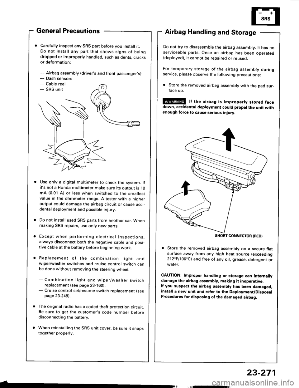
- Dash sensors- Cable reel- SRS unit
General Precautions
Carefully inspect any SRS part before you install it.Do not install any part that shows signs of beingdropped or improperly handled, such as dents, cracksor deformation:
- Airbag assembly {driver's and front passenger's)
Airbag Handling and Storage
Do not try to disassemble the airbag assembly. lt has noserviceable parts. Once an airbag has been operated(deployed), it cannot be repaired or reuseo.
For temporary storage of the airbag assembly duringservice, please observe the following precautions:
. Store the removed airbag assembly with the pad sur-face up.
!@ It the airbag is impropsrty stored facsdown, accidental deployment could propel the unit withenough force to cause setious iniury
Store the removed airbag assembly on a secure flatsufface away from any high heat source (exceeding
212"Fl1OO'Cl and free of any oil. grease, detergent or
CAUTION: lmproper handling or storage can internallydamage the airbag assembly, making it inoperativ€.ll you suspect the airbag assembly has been damagod,install a new unit and rgler to the Deployment/DigposalProcedures lor disposing of the dsmaged airbag.
Use only a digital multimeter to check the system. lfit's not a Honda multimeter make sure its output is 10mA (0.01 A) or less when switched to the smallestvalue in the ohmmeter range. A tester with a higheroutput could damage the airbag circuit or cause accidental deployment and possible injury.
Do not install used SRS parts from another car. Whenmaking SRS repai.s, use only new pans.
Except when performing electrical inspections,always disconnect both the negative cable and posi-
tive cable at the battery before beginning work.
Replacement of the combination light andwiper/washer switches and cruise control switch canbe done without removing the steering wheell
- Combination light and wiper/washer switchreplacement (see page 23-160).- Cruise control sevresume switch replacement {seepage 23-2491 .
The original radio has a coded theft protection circuit.Be sure to get the customer's code number beforedisconnecting the battery.
When reinstalling the SRS unit cover, be sure it snapstogether properly.
SHORT CONNECTON {REDI
23-271