Page 979 of 1413
Seats
Rear Seat Replacement (cont'd)
Sedan
NOTE: Take care not to scratch the seal covers and
booy.
1. Fold the seat-back forward.
2. Remove the clips.
V : Clip locations, I
SEAT-8ACK
l
/-.;- I----+tl l---M- I
/ /,/
TRUNK MAT
SEAT-BACK
20-110
3. Detach the hook, then remove the trunk mat.
TRUNKMAT
a-^I{ \
Nry
YHOOK
SEAT.BACK
TRUNKMAT
4. Remove the bolts. then remove the seat-back.
V : Eolt locations, 4
REAR SEAT LAICH/LOCK CYLINDER{see page 2O-'l 1 1l
REAR SEATPIVOT BRACKET(see page 2O-1 1 1)
REAR SEATPIVOT BRACKET
I
I gel?"Til.*,,", i
E 7.2 tbt'trl I" -----r"
SEAT.BACK
Page 980 of 1413

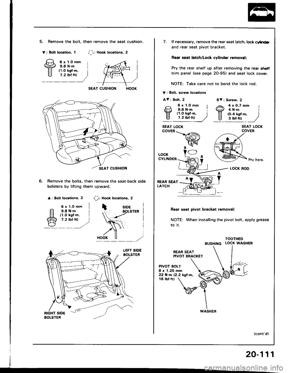
5. Remove the bolt, then .emove the seat cushion.
Y: Bolt location. 1i -r i Hool loc.lion3. 2
6r1.0mm i9.8 N.m I
SEAT CUSHION
Remove the bolts, then remove the seat-back side
bolsters by lifting them upward.
: Bolt locationr, 2 r'): Hook locetions, 2
6 r 1.o mm I9.8 N.m i(1.0 kgl'm, I7.2 tbt.fti )
BV : Sc?ow, 2
SEAT LOCKCOVER
Pry here.
LOCK ROD
R6ar seat pivot brackol removal:
NOTE: When installing the pivot bolt, apply grease
to it.
TOOTHED
BUSHTNG LOCK WASHER
REAR SEATPIVOT BRAC(ET
PIVOT BOLT8 x 1.25 mm22 N.m (2.2 kgf m,16 tbf.ftt
20-111
7. lf necessary, remove the rear seat latch, lock c!ftiab
and rear seat pivot bracket.
Roar soat latch/Lock cylinder r€moval:
Pry the rear shelj up after removing the rear shelttrim panel (see page 2O-95) and seat lock cover.
NOTE: Take care not to bend the lock rod.
V i Bolt. scrow locations
AV i Boll, 2
9: l;o--' I4x0.7mm I4 N.rrt
EI lr.o tgf .m, Iv_ 7.2 tbf.ft!____//
9.8 tt.m il1.O kgf.m, I{O.4 kgf'm, )3tbt.ttt J
SEAT LOCKcovER\-_L/-R\
wB -"1/ -
LOCKCYLINDER
REAR SEATLATCH
WASHER
Page 1024 of 1413

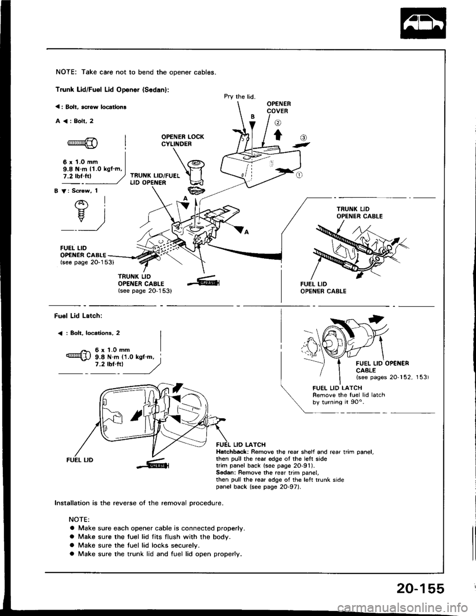
NOTE: Take care not to bend the opener cables.
Trunk Lid/Fuel Lid Oponer {Sodan}:
< : Bolt, scrow locatlon!
A<:Bolr,2
OPENER LOCKCYLINDER
TRUNK LID/FUELLID OPENER
B V: Scrow, 1
AI-}{- IH. I
_:_)
FUEL LID
Pry the ljd.OPENERCOVER
o
to-*rr*@
6 r 1.0 mm
()t
OP€NER CABLE(seo page 2O-153)
TRUNK LIDOPENER CABLE(see page 20-1 53)
9.8 N m 11.O kgl m,
Fuol Lid Lstch:
< : Boh, locotions, 2
6r1.0mm
FUEL LID OP€NERCAALE(see pages 20-152, 153)
9.8 N m 11.0 ksl'm, i7 '2 tbt'''l
------,//
FUEL LID
lnstallation is the reverse of the removal orocedure.
NOTE:
a Make sure each opener cable is connected properly.
a Make sure the fuel lid fits flush with the body.
a Make sure the tuel lid locks securelv.
a Make sure the trunk lid and fuel lid open properly.
LIO LATCHHatchbock: Remove the rear shelf and rear trim oanel.then pull the rear edge ot the lett sidetrim panel back (soe page 2O-91).Sodan: Remove the rear trim panel,then pull the rear edge of the left trunk sidepanel back {see page 2O-971.
FUEL LIO LATCHRemove the fuel lid latchby turning it 90o.
20-155
Page 1025 of 1413
Hatch Latch and Lock CYlindet
Replacement
NOTE: Take care not 10 bend the cylinder rod and hatch
opener cable.
1. Remove the rear trim panel (see page 20-921.
2. Disconnect the cylinder rod and connector.
3. Remove the hatch latch.
>: Screw locatiois, 3
^ 6x1.omm I
{Dm s.e N m (1.0 ksl m,- ,?tb:tn __/
20-156
4. Disconnect the hatch opener cable.
HATCH LATCH
5. Remove the lock cylinder by turning it 45o
>: Bolt localion, 1
o.
CYLINDER ROD
lnstallalion is the reverse of the removal procedure.
NOTE:
a Apply grease to the hatch latch.
HATCH LATCH
Make sure the hatch locks securely.
Make sure the hatch opens properly.
Make sure the connector is connected properly.
a
a
a
Page 1026 of 1413
Trunk Lid Latch and Lock Cylinder
Replacement
NOTE: Take care not to bend the cylinder rod and trunklid opener cable.
l. Disconnect the connector and trunk lid opener cable.
CONNECTOR
2. Disconnect the cylinder rod.
CYLINDERROD
Remove the bolts, then remove the trunk lid latch.
A : Bolt locations, 3
LIDCABLE
4. Remove the lock cylinder cover.
HOOKS
LOCK CYLINDERCOVER
5. Remove the bolt, then pull the lock cylinder out. Re,move the lock cylinder trom the cylinder rod, thentake them out.
: Bolt location, 'l
CLIP
CLIPS
F 6xl.Omm I
q;i!!"jy
LOCKCYLINDER
CYLINDER ROD
6. Installation is the reverse ol the removat proceoure.
NOTE:
a Apply grease to the trunk lid latch,
a Make sure the trunk lid locks securelV.a Make sure the trunk lid opens properly.a Make sure the connector is connected properly.
/ ./,.,
,/'e4
20-157
Page 1122 of 1413

Gonnector ldentification and Wire Harness Routing
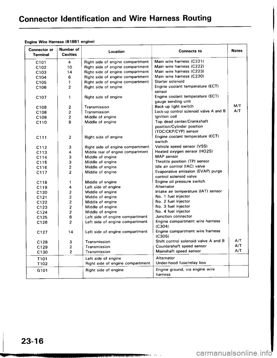
Engine Wire Harness {B1881engine)
Connector 01
Terminal
Number of
CavitiesLocationConnects ioNotes
c10'l
c102
c103
c104
c 105
c106
c107
c108
c108
c109
c110
c111
c113
c114
c115
Lt to
c117
c118
c119
c't 20
c121
c122
c123
cl24
c125
c't26
c127
c128
c129
c130
10
14
6
1
1
2
2
8
2
3
t
1
2
2)
2
8
14
2
2
Right side of engine compartment
Right side of engine compartment
Right side of engine compartment
Right side ol engine compartment
Right side of engine compartment
Right side of engine
Right side ol engine
Transmission
Transmission
Middle of engine
lvliddle of engine
Right side ot engine
Right side of engine compartment
ldiddle rear of engine compartment
Middle of engine
Middle ol engine
Middle of engine
Middle of engine
Middle ot engine
Left side of engine
lvliddle of engine
Middle of engine
Middle of engine
Middle ot engine
Middle ol engine
Left side of engine compartment
Left side of engine compartment
Left side of engine compartment
Transmission
Transmission
Transmission
Main wire harness (C221)
Main wire harness {C222}
Main wire harness (C223)
Main wire harness {C220)
Starter solenoid
Engine coolant temperature {ECT)
sensor
Engine coolant temperature (ECT)
gauge sending unit
Back'up light switch
Lock-up control solenoid valve A and B
lgnition coil
Top dead center/Crankshaft
position/Cylinder position
(TDC/CKP/CYP) sensor
Engine coolant temperature (ECT)
switch
Vehicle speed sensor (VSS)
Heated oxygen sensor (HO2S)
MAP sensor
Throttle position (TP) sensor
ldle air control (lAC) valve
Evaporative emission (EVAPI purge
control solenoid valve
Engine oil pressure switch
Alternator
Intake air temperature {lAT} sensor
No. 'l fuel injector
No. 2 tuel injector
No. 3 fuel injector
No. 4 fuel injector
Junction connector
Engine compartment wire harness
(c304)
Engine compartmenl wire harness
(c305)
Shift control solenoid valve A and B
Countershait speed sensor
Mainshaft speed sensor
M/T
NT
NT
NT
T 101
r102
Lelt side oI engine
Right side of engine compartment
Alternator
Under-hood tuse/relay box
G 101Right side of engineEngine ground, via engine wire
harness
23-16
Page 1140 of 1413
Connector ldentification and Wire Harness Routing
Drlvar's Door Wir6 Hamors
Connectot 01
Torminal
Number of
CavitlesLocationConnocts toNotos
c601
c602
c603
c604
c605
c605
c606
c607
c608
c609
c610
c61 1
c612
25
2
4
14
I
I
10
10
o
2
I
Driver's door
Driver's door
Driver's door
Driver's door
Behind mirror panel
Driver's door
Driver's door
Driver's door
Driv€r's door
Driver's door
Driver's door
Oriver's door
Driver's door
Oriver's door wire harness (C506)
Driver's door speaker
Driver's power window motor
Power door lock control unit
Left power mirror
Left power mirror
Lett tweeter
Driver's door lock switch
Power mirror switch
Power window master switch
D.iver's door lock actuator as-
sembly
Driver's key cylinder switch
Power window master switchSedan
Hatchback
Sedan
818C1
engrne
23-34
Page 1203 of 1413

Spark Plug Inspection
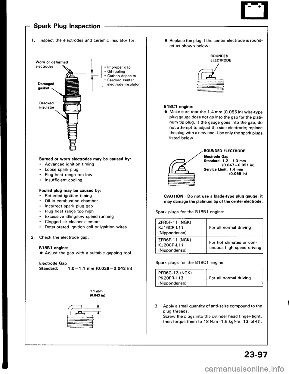
1. Inspect the electrodes and ceramic insulator for:
. rmproper gap. Oil-touling. Carbon deposits. Cracked centerelectrode insulatorDamagedgask6t
Burned or worn electlodes may be caused by:. Advanced ignition timing. Loose spark plug. Plug heat range too low. Insufficient cooling
Fouled plug may be caused by:. Retarded ignition timing. Oil in combustion chamber. lncorrect spark plug gap. Plug heat range too high. txcessive idling/low speed running. Clogged air cleaner element. Deteriorated ignition coil or ignition wires
Check the electrode gap.
Bl88l engine:
a Adjust the gap with a suitable gapping tool.
Electrode Gap
Standard: 1.0-1.1 mm (O.O39-0.O43 in)
1.1 mm{0.0,$ in)
Replace the plug if the center electrode is round-
ed as shown below:
ROUNDEDELECTROOE
Bl8Cl engine:
a Make sure that the '1.4 mm (0.055 in) wire-typeplug gauge does not go into the gap for the plati-
num tip plug. lf the gauge goes into the gap, do
not attempt to adjust the side electrode; replace
the plug with a new one. Use only the spark plugs
listed below.
ROUNDEO ELECTRODE
Electrode GapStandard: 1 .2-'l .3 mm{0.047 -O.051 in)Service Limit: 1.4 mm{0.055 in)
CAUTION: Do not use a blade-type plug gaugs, it
may damage the platinum tip of the center olectrodo.
Spark plugs for the 81881 engine:
Spark plugs for the B'l8Cl engine:
PFR6G_13 (NGK) IPK2OPR-113 I For all normal driving
{Nippondenso)
3. Apply a small quantity ol anti-seize compound to the
plug threads.
Screw the plugs into the cylinder head iingef-tight,
then torque them to 18 N.m (1.8 kgf.m, 13lbf.ft).
ZFRsF-1 1 (NGK)
KJl6CR-11 1
(Nippondenso)
For all normal driving
ZFR6F-1 1 (NGK)
KJ2OCR-11 1(Nippondenso)
For hot climates or con-
tinuous high speed driving
23-97