Page 92 of 1413

Cylinder Head
Installation (cont'dl
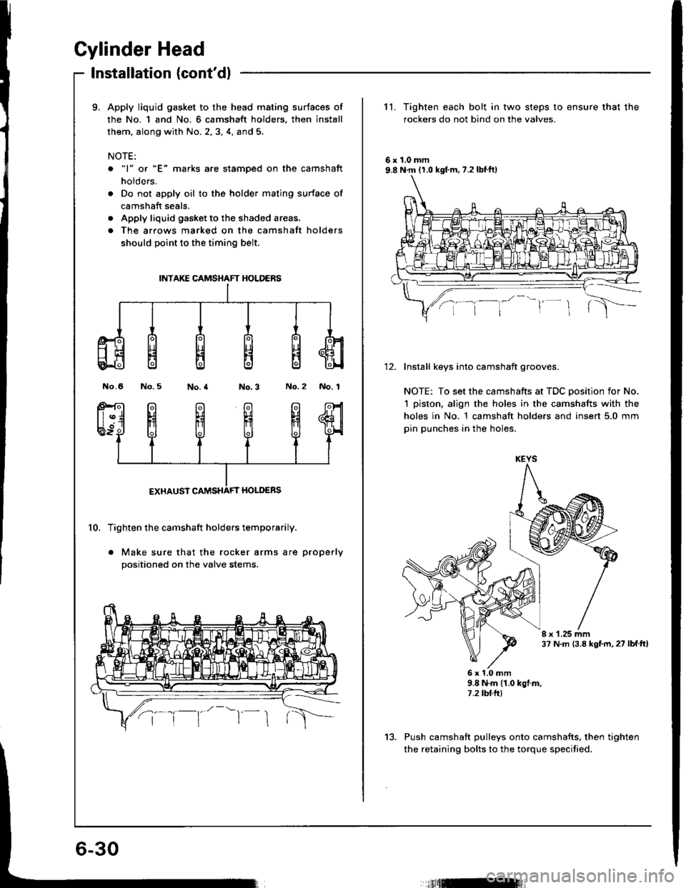
9. Apply liquid gasket to the head mating surtaces of
the No. 1 and No. 6 camshaft holders, then install
them, along with No. 2,3, 4, and 5.
NOTE:
o "1" or "E" marks are stamoed on the camshaft
holders.
. Do not apply oil to the holder mating surface of
camshaft seals.
. Apply liquid gasket to the shaded areas.
. The arrows marked on the camshatt holders
should point to the timing belt.
No.6 No.5No.2 No. 1
10. Tighten the camshaft holders temporarily.
. Make sure that the rocker arms are properly
positioned on the valve stems.
INTAKE CAMSHAFT HOLDERS
11. Tighten each bolt in two steps to ensure that the
rockers do not bind on the valves.
6r1.0mm9.8 N.m 11.0 kgf.m,7.2lbtft)
Install keys into camshaft grooves.
NOTE: To set the camshafts at TDC position for No.
1 piston, align the holes in the camshafts with the
holes in No. 1 camshaft holders and insert 5.0 mm
pin punches in the holes.
I r 1.25 mm37 N.m {3.8 kgf.m, 27 lbf.ttl
6x1.0mm9.8 N.m (1.0 kgf.m,7.2 tbtft)
Push camshaft pulleys onto camshafts, then tighten
the retaining bolts to the torque specified.
KEYS
13.
tfitml
Page 93 of 1413
14.
16.
Installthe timing belt {see page 6-12).
Adjust the valve clea.ance (see page 6-31.
Install the rubber seal in the groove of the cylinder
head cover. Seat the seal in the recesses for thg
camshaft first, th€n work it into the groove around
the outside edges,
NOTE:
. Before installing the rubber seal, thoroughly
clean the seal and the groove.
. When installing, make sure the seal is seated
securely in the corners of the recass€s with no
gap.
CYUNDER HEADCOVER
RUBAER SEAL
17.Apply liquid gask€t to the rubber seal at the eight
corners of the recesses.
NOTE:
. Use liquid gaskst, Part No. 08718 - 0001.
. Check that the mating surfaces are cl€an and dry
before applying liquid gasket.
. Do not install the parts if 20 minutes or mor6
havs elapsod sinco applying liquid gasket.
Instead, reapply liquid gasket after removing old
reaidue.
. After assembly, wait at lsast 20 minutes before
filling the engine with oil.
Apply liquid g.sket tothe shaded areas.
(cont'd)
6-31
Page 95 of 1413

Cylinder Head/Valve Train
818C1 engine
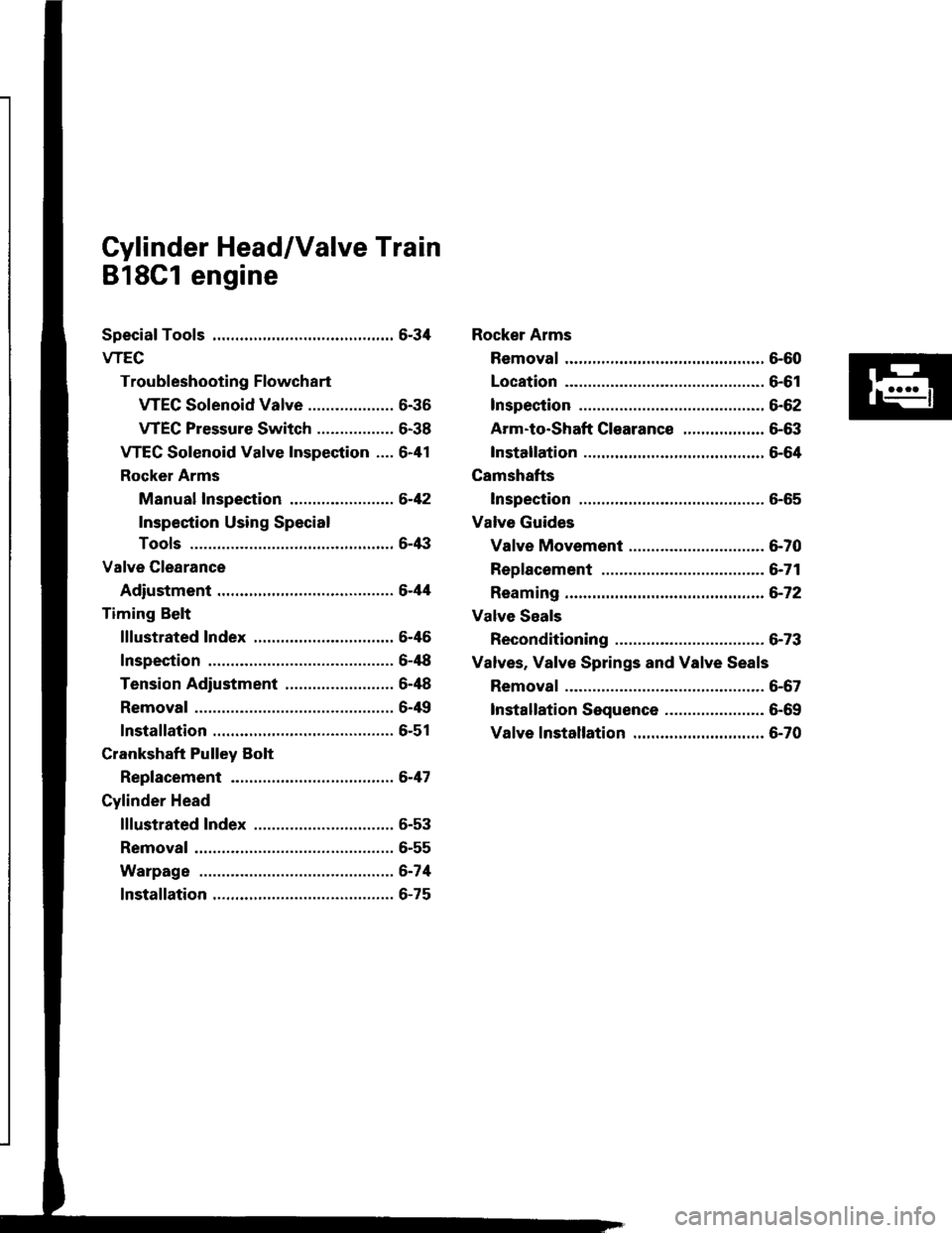
Special Tools ............. 6-34
wEc
Troubleshooting Flowchart
WEC Solenoid Valve ................... 6-36
VTEC Pressure Switch ................. 6-38
VTEC Solenoid Valve Inspection .... 6-41
Rocker Arms
Manual Inspection .....,................. 6-42
Inspection Using Special
Tools ....................................,.....,.. 6-/|i|
Valve Glearance
Adiustment ............ 6-44
Timing Belt
lllustrated 1ndex ............................... 6-46
Inspection .............. 6-48
Tension Adiustment ........................ 6-48
Removal ................. 6-4{l
lnstallation ............. 6-51
Crankshaft Pulley Bolt
Replacement .........6-47
Cylinder Head
lllustrated Index ............................... 6-53
Removal .................6-55
Warpage ................6-74
lnstallation ............. 6-75
Rocker Arms
Removal ................. 6-60
Location ................. 6-61
lnspection .............. 6-62
Arm-to-Shaft G|earance .................. 6-63
Installation ............. 5-64
Camshafts
Inspection .............. 6-65
Valve Guides
Valve Movement .............................. 6-70
Replacement .........6-71
Reaming ................. 6-72
Valve Seals
Reconditioning ......6-73
Valves. Valve Springs and Valve Seals
Removal ................. 6-67
lnstallation Sequence ..........,.......,... 6-69
Valve lnstallation ............................. 6-70
Page 96 of 1413
SpecialTools
Tool NumbarDctcriptionPlea Rctllanca
6-72
6-17
&45
6-43
6-11
6-67
6-71,72
6-67
Valve Guide Reamer, 5.5 mm
Holder Handle
Tappet Adiuster Wrench
Air Stoppet
Pulley Holder Attachment, HEX 50 mm,
Offset
Valv€ Spring Compressor Attachment
Extension
Valve Guide Driver, 5.5 mm
Valve Spring Compressor Attachment
07HAH - PJ7010A or
OTHAH _ PJTOIOB
07JAB - 001020A
07LAA - PR30100
OTLAJ _ PR3O2OA
07MAB. PY3OlOA
OTMAF _ PRgO'IOA
07742 - 0010100
07757 - PJ 1010A
o
@
@
@
/.\
o
o
@
o@
@o@
o@@
6-34
Page 101 of 1413
VTEC
Troubleshooting FlowchartVTEC Pressure Switch (cont'dl
lFrom pag6 6-39)
Disconnsct lhe 1P connectortrom the VTEC sol6noid valve.
Attach the battery positivo torminal to the GRN/WHT terminal.
Start the engine and chgck oilpressure at 5,000 rpm (lor VTECoil pr€ssure test).
ls pressure above 400 kPa(4kgt/cm,, 60 psi)?In.p.ct th. VIEC .olrnoid v.lv..
Check tor continuity betwe6n the2 terminsls on th€ VTEC prsssure
switch !nder above condition.
Sub.titut. . klown-eood ECMand rachack. |f aymplom/indica-tion goaa away rrplaca th. o?igi-n.l ECM.
u
OOMMERCIALLY AVAILABIIOIL PRESSURE GAUGE
GAUGE JOIMf ADAPIORSNAPON MT2S1'10x 1.0 mm. Use new washer wheninstalling th6 soaling bolt.NOTE:Keep moasuring tim6 as shon 6s possi-
ble because engine i5 running with noload lless than ono minuto).
Page 102 of 1413
WEC Solenoid Valve Inspection
Disconnect the 1P connector trom the VTEC
solenoid valve.
M€asurs resistance between th€ terminal 8nd body
grouno.
R.3bt!nc!: 1l - 30 O
lf the resistance is within specificstions, romove the
WEC sol€noid valve from the cvlindor hsad, and
check the VTEC solenoid valve filter for clogging.
. lf there is clogging, replacs the engin€ oil filter
and the engine oil.
VTEC SOT.CNOTD
12 tTln 11.2 kg[.m,8.7 lbttt]
6-41
4. lf th6 filter is not clogged, push the VTEC solenoid
valv€ with your finger and check its movement.
. lf VTEC solsnoid valve is normal, check the
engins oil pr€ssure.
6x1.0mm
Page 104 of 1413

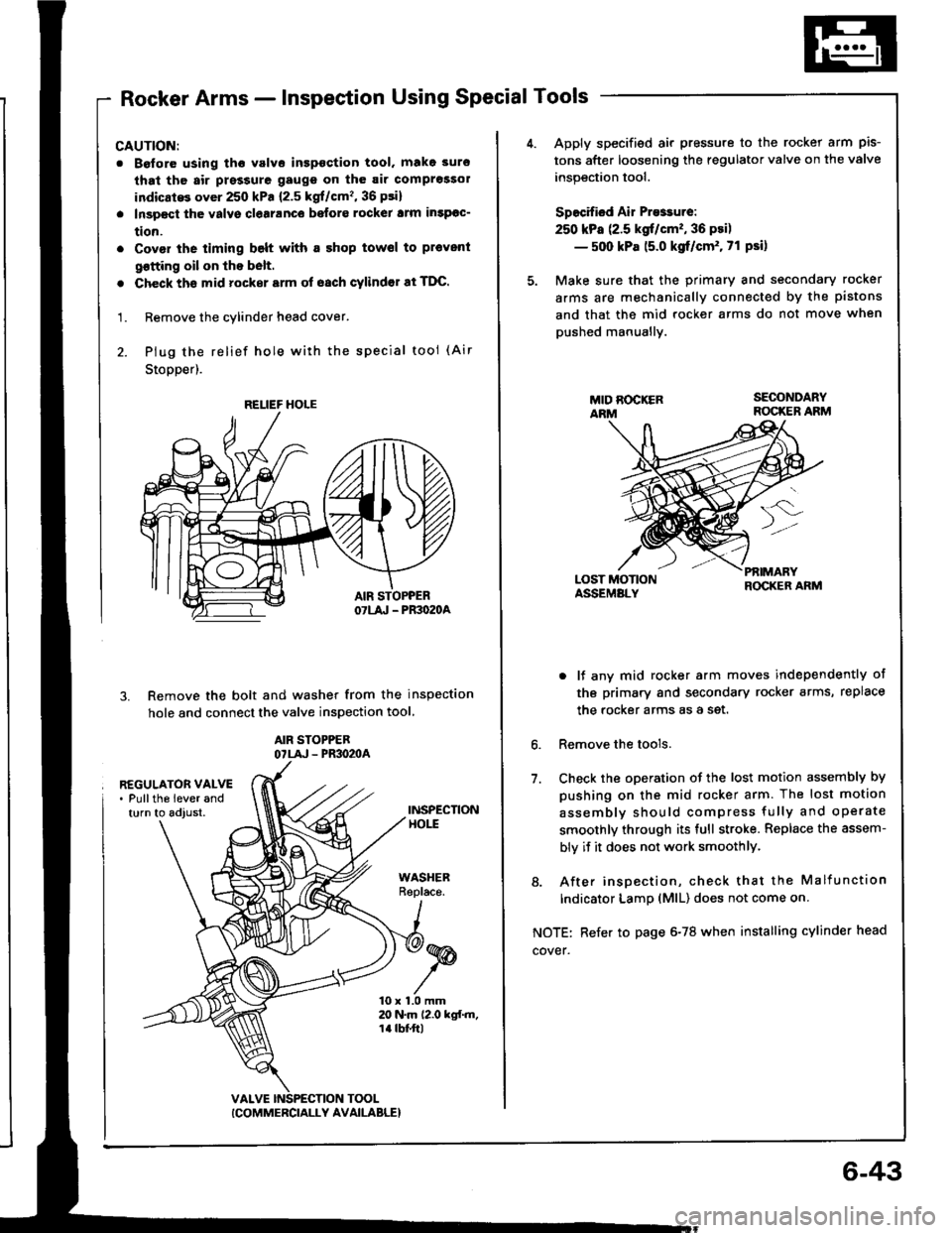
Rocker Arms - Inspection Using Special Tools
CAUTION:
. Boforo using tho valvo inspoction tool. make 3uro
that th6 air prsssure gaugs on th6 air comprossol
indicatG over 250 kPa {2.5 kgf/cm'�, 36 psi}
. Inspect the valvs clearanco befors rockel lrm insPoc-
tion.
. Covor the timing belt with a shop towsl to pl€vent
qotting oil on lhe b6lt.
. Check ths mid rocker srm of oach cylindor at TDC.
1. Remove the cylinder head cover.
2. Plug the relief hole wiih the special tool (Air
Stopper).
Remove the bolt and washer from the inspection
hole and connect the valve inspection tool
AIR STOPPEBOTLA' - PR3O2OA
3.
REGULATOR VALVE. Pullths lever andturn to adjust.INSPECTIONHOtt
WASHERReplace.
10 x 1.0 mm20 N.m 12.0 kgf.m,1a tbt'ft|
TOOL
RELIEF HOLE
ICOMMERCIALLY AVAILABLE}
6-43
Apply specified air pressure to the rocker arm pis-
tons after loosening the regulator valve on the valve
inspection tool.
Specified Air Presrure:
250 kPa (2.5 kgt/cm'�, 36 psi)
- 500 kPa 15.0 kgf/cm'. 71 Psi)
Make sure that the primary and secondary rocker
arms are mechanically connected by the pistons
and that the mid rocker arms do not move when
pushed manuallv.
LOST MOTIONASSEMALY
PfiIMARYROCKER ARM
6.
7.
o lf any mid rocker arm moves independently of
tho primary and secondary rocker arms, replace
the rocker arms as a set.
Remove the tools.
Check the oDeration of the lost motion assembly by
pushing on the mid rocker arm. The lost motion
assemblv should compress fully and operate
smoothly through its full stroke. Replace the assem-
bly if it does not work smoothlY.
8. After insoection, check that the Malfunction
Indicator LamD (MlL) does not come on
NOTE: Refer to page 6-78 when installing cylinder head
cover.
Page 105 of 1413

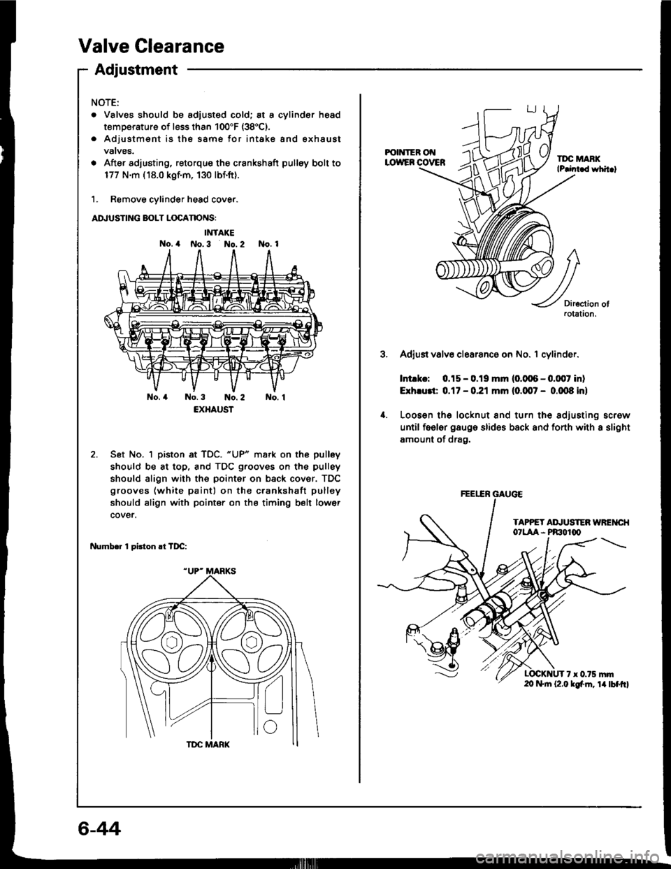
Valve Clearance
Adiustment
NOTE:
. Valves should be adjusted cold; at a cylinder head
temperature of less than 100"F (38'C).
. Adjustmsnt is the same for intake and exhaust
vatves.
o After adjusting, retorque the crankshaft pulloy bolt to
177 N.m ( 18.0 kgf.m, 130 lbf.ft).
1. Remove cylinder head cove..
ADJUSTING BOLT LOCANONS:
IMTAKE
No. 4 No.3 No. 2 No. 1
No.4 No.3 No.2 No. 1
EXHAUST
Set No. 1 piston at TDC. "UP" mark on the pulley
should be at top, and TDC grooves on the pulley
should align with the pointer on back cover. TDC
grooves (white paint) on the crankshatt pulley
should align with pointer on the timing belt lower
cover.
Numbr. 1 pirton .t TDC:
6-44
FOI{IER Ot{LOWEF COVERTDC MANKlP.int d whit.t
3.
4.
Diroction ofaotation.
Adjust valv6 clearanc6 on No. 1 cylinder.
Intlkc: 0.15 - 0.19 mm (0.006 - 0.0,07 inl
Exh.u3t 0.17 - 0.21 mm (0.007 - 0.m8 inl
Looson lh6 locknut and turn the adjusting screw
until feeler gaugo slides back and fonh with a slight
amount of drag.
TAPPET AI\,USTEN WREI{CI{O'LAA - PRIOIq'
7 x 0.75 mrn20 f+|n (2.0 kgf'm. 14lbtftl
FEEEN GAUGE