Page 1101 of 1413

A/C Compressor Belt
Replacement
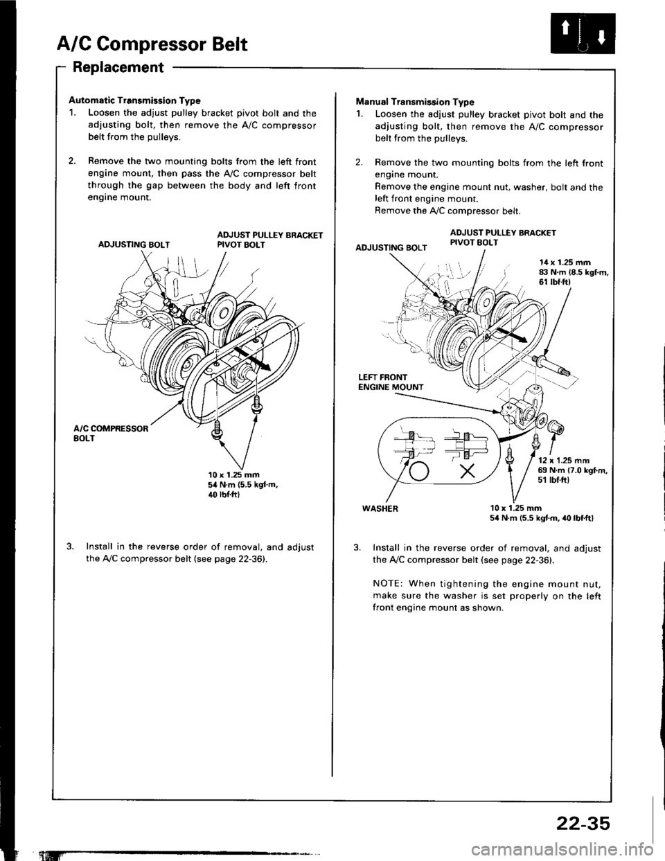
Automatic Transmission Type
1. Loosen the adjust pulley bracket pivot bolt and the
adjusting bolt, then remove the A/C compressor
belt from the oullevs.
2, Remove the two mounting bolts from the left front
engine mount, then pass the A,/C compressor belt
through the gap between the body and left front
en9rne mount.
ADJUSTING BOLTADJUST PULLEY BRACKETPIVOT BOLT
10 x 1.25 mm54 N.m (5.5 kgf.m,4(' rbr.ft)
Install in the reverse order of removal, and adjust
the A,/C compressor belt (see page 22-36).
"t.M'
22-35
-la ar-
Manual Transmission Type
1. Loosen the adjust pulley bracket pivot bolt and the
adjusting bolt, then remove the A/C compressor
belt from the pullevs.
2. Remove the two mounting bolts from the left front
engane mount.
Remove the engine mount nut, washer, bolt and theleft front engine mount.
Remove the A,./C comoressor belt.
ADJUSTING BOLT
ADJUST PULLEY BRACKETPIVOT EOLT
l!l',
I
14 x 1.25 mm83 N.m 18.5 kgl.m.61 tbf.ft)
LEFT FRONTENGINE MOUNT
12 x'1.25 mm69 N.m {7.0 kgf.m,51 tbf.ftt
WASHER
Install in the reverse order of removal, and adjust
the Ay'C compressor belt (see page 22-36).
NOTE: When tightening the engine mount nut,
make sure the washer is set properly on the left
front engine mount as shown.
10 x 1.25 mm54 N.m (5.5 kgtm, irc lbf.ft)
Page 1182 of 1413

Starting System
Startel Test
NOTE: The air temDerature must be between 59 8nd
10OoF (15 and 38oC) before testing.
Recommendsd Procodure:
a Use a staner svstem tester.
a Connect and operate the equipment in accordance
with the manutacturer's instructions.
a Test and troubleshoot as described.
Altohato Procedure:
a Use the following equipment:- Ammeter. 0-4OO A- Voltmeter, O- 20 V {accurate within 0.1 volt)
- Tachometer, O- 120O rpm
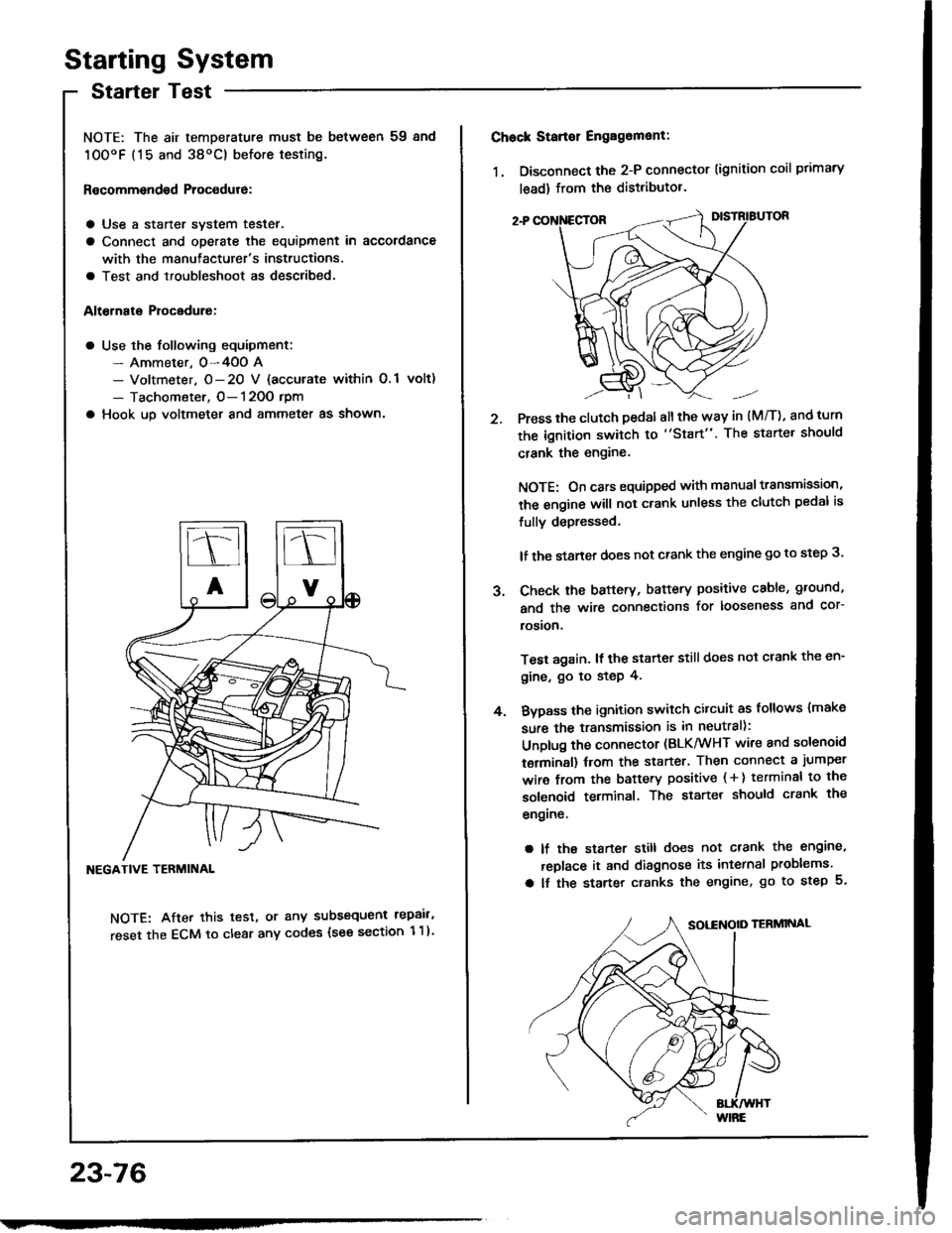
a Hook up voltmeter and ammeter as shown'
NEGATIVE TERMINAL
NOTE: After this test, or any subsequent repair,
reset the ECM to clear any codes (see section 1 1)
23-76
2.
Chock Stan€r Engag6ment:
1. Disconnect the 2-P connector (ignition coil primary
lead) from the distributor.
Press the clutch pedal allthe way in (M/T), and turn
the ignition switch to "Start". The starter should
crank the engine.
NOTE: On cars equipped with manual transmission,
the engine will not crank unless the clutch pedal is
fully depressed.
lf the staner does not crank the engine go to step 3.
Check the baftery, battery positive cable, ground,
and the wire connections for looseness and cor-
rosion,
Test again. lf the starter still does not crank the en-
gine, go to step 4.
Bvpass the ignition switch citcuit as follows {make
sure the transmission is in neutral):
Unplug the connector (BLK/WHT wire and solenoid
terminsl) trom the starter. Then connect a jumper
wire from the battery positive ( + ) terminal to the
solenoid terminal. The starter should crank the
engrne.
a lf the starter still does not crank the engine,
replace it and diagnose its internal problems.
a lf the starter cranks the engine, go to step 5.
J.
4.
Page 1183 of 1413

5. Check lor 8n op€n in the BLKMHT wire circuit be-
tween the staner and ignition switch, and con-
nectors.
6. Check the ignition switch (see page 23-70).
7, On cars with automatic transmission, check the A/Tgear position switch (neutral position switchl and
connector. On cars with manualtransmission, check
the staner cut relay, clutch interlock switch, and
connectors.
NOTE: Check the No. 39 (5O A) fuse in the under-hood
fuse/relay box for the starter cut relay.
Check tor Woar and Damago:
The starter should crank the engine smoothly and stead-
ily. lf th€ startsr engages, but cranks the engine errati-
cally, remove it. Inspect the starter, drive gear, and
flywheel ring gesr for damage.
a Check the drive gear overunning clutch for binding
or slipping when the armature is rotated with the drivegear held. Replace the gesrs if damaged.
Check Cranking Voltago 8nd Current Draw:
Cranking voltage should be no less than 8.O volts.
Current draw should be no more than 360 amperes.
lf cranking voltag€ is too low, or current draw too high,
check for:
a Fully charged battery
a Open circuit in starter armature commutatot segments
a Starter armature dragging
a Shoned armature winding
a Excessive drag in engine
Chack Cranking rpm:
Engine spsod during cranking should be above 1O0 rpm.
lf spe6d is too low, ch€ck for:
a Loose battsry or starter teminals
a Excessively worn starter brushes
a Open circuit in commutator segments
a Dirty or damaged helical spline or drive gear
a Defective drive gear overrunning clutch
Chock StErtor Disongagomoni:
Press the clutch pedal allth€ way in (M/T), turn the ioni-
tion switch to "lll" and rolease to "11".
The starter drive gear should disengage from the tlywheel
ring gear. When you rolease the key.
lf the drive gear hangs up on th€ flywheel ring gear, check
for:
a Solenoid plunger and switch malfunction
a Dirty drive gear assembly or damaged overrunning
clutch
23-77
Page 1286 of 1413

Back-up Lights
Manual Transmigsion:
NOTE: Check the No. 1 5 { 1 O A) fuse in the under-dash
fuse/relay box befote testing.
'1. Test the back-up light switch by placing the shift
lever in reverse and turning the ignition switch to ON
(
).
2. It the back-up lights do not go on, check the back-
up light bulbs in the taillight assembly.
3. lf the tuse and bulbs are OK. disconnect the connec-
tor from the back-up light switch.
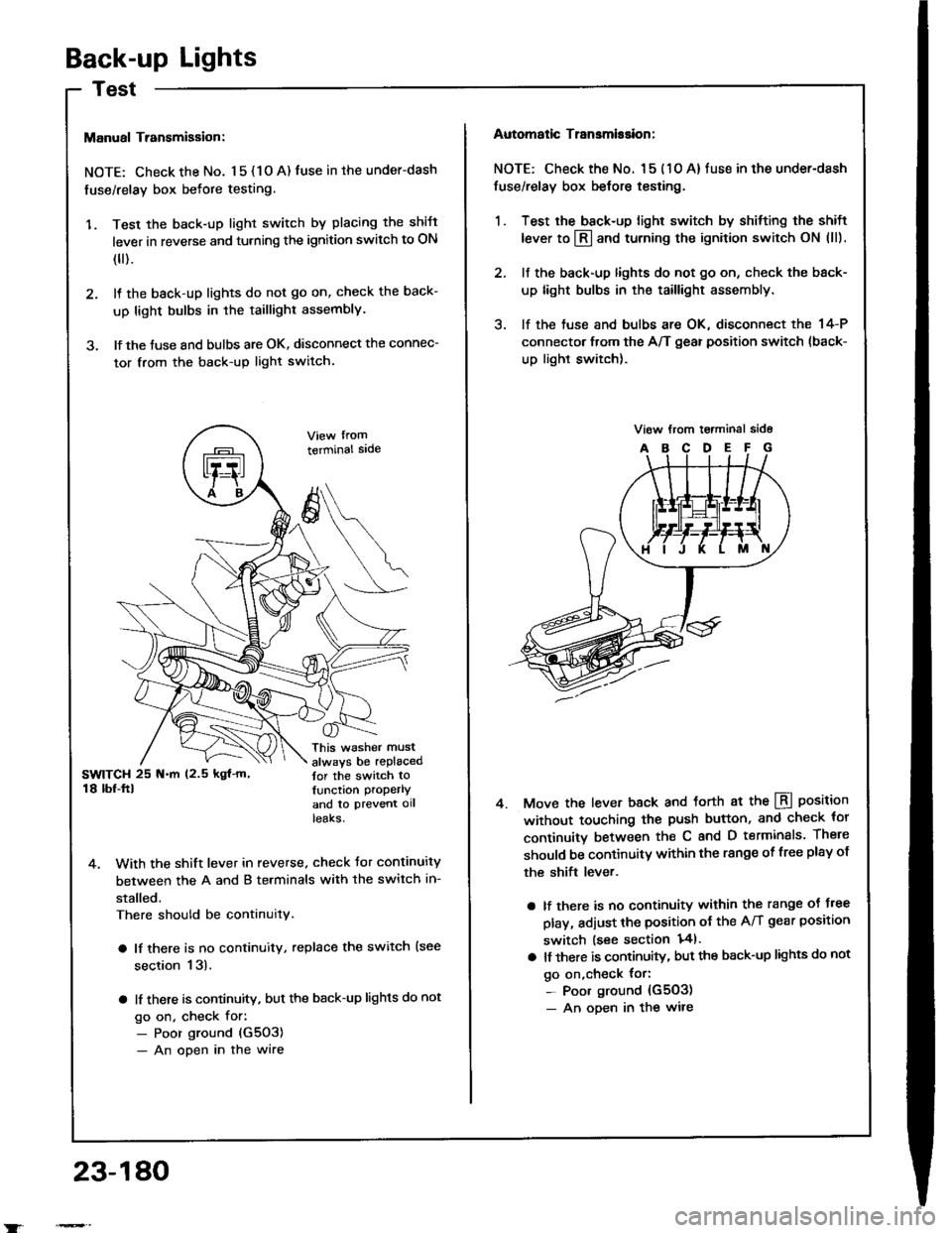
terminal sade
This washer must
always be replacedtor the switch tolunction properlY
and to ptevent ollteaKs.
4. With the shift lever in reverse. check Jor continuity
between the A and B terminals with the switch in-
stalled.
There should be continuity.
a lf there is no continuity, replace the switch {see
section 13).
a lf there is continuity, but the back-up lights do not
go on, check for:- Poor ground (G5O3)
- An open in the wire
23-180
Automatic Transmission:
NOTE: Check the No. l 5 ( 1 O A) fuse in the under-dash
fuse/relay box belore testing.
1. Test the back-up light switch by shitting the shift
lever to l3l and turning the ignition switch ON (ll).
2. lf the back-up lights do not go on, check the back-
up light bulbs in the taillight assembly.
3. lf the tuse and bulbs are OK, disconnect the 14-P
connector from the A/T gear position switch (back-
up light switch).
Move the lever back and torth at the LBI position
without touching the push button, and check tor
continuitv between th€ C and D terminals. There
should be continuitY within the range of free plsy of
the shift lever.
a lf there is no continuity within the range oJ J.ee
play, adjust the position ot the A/T gear position
switch lsee section 141.
a lt there is continuity, but the back-up lights do not
go on,check {or:- Poor ground {G503)- An oDen in the wire
4.
Page:
< prev 1-8 9-16 17-24