1994 ACURA INTEGRA Manual transmission
[x] Cancel search: Manual transmissionPage 143 of 1413

lllustrated Index
NOTE:
. Apply liquid gasket to the mating surfaces of the right
side cover and oil pump housing before installing
them.
. Use liquid gasket, Pan No.08718 - 0001.
. Clean the oil pan gasket mating surfaces before
installing it.
Bl8Bl engine: wAsHEF
Lubricate all internal parts with engine oil during
reassemory.
6x1.0mm12 N.m (1.2 kgf.m,I lbf.ftl
6x1.0mm11 N.m (1.1 kgf.m,8lbtft)
OIL SCREEN
11 x 1.25 mm76 N.m17.8 kgl.m, 56 lbf ftlApply engine oilto the bolt
threads and the washers.NOTE: After torquingeach cap, turn crankshaftto check lor binding.
DRAIN PLUG44 N.m {4.5 kgf.m,33 tbtfr)
GASKETReplace.
6x1.0mm1'l N.m {1.1 kgt.m, I lbtft)
OIL PAN
O.RING
GASKETReplace.
BEARING CAP
12 x 1.0 mm103 N.m (10.5 kgf.m, ?6lbf ft)
MANUALFLYWHEEL
'12 x 1.0 mm74 N.m {7.5 kgt m,54lbf.ftlTorque sequence, page 7 7
DRIVE PLATECheck for cracks,
AUTOMATIC TRANSMISSION
WASHER
6x1.0mm11 N.m {1.1 kgl.m,8 tbf.frt
CRANKSHAFTEnd play, page 7-12Runout, Taper, andOut-of-Round, pages 7 12, 13Instsllation, page 7 22
MAIN BEARINGRadial clearance, page 7-8
Sel€ction, page 7-8NOTE: New main bearingsmust be selected by matching
crank and block identificationmarkrngs.
Apply liquid gasket
to block mating surface.
OIL SEALInstallation, page 7-25,
RIGHTSIDE COVERDOWEL PINSOIL PUMPOverhaul, page 8-9THRUST WASHERSGrooved sides face outward.NOTE: Thrust washer thicknessis tixed and must not be changedby grinding or shamming.
8 x 1 .25 mm2,1 N.m {2.4 kgt m,17 tbt.ft)
OIL SEALInstallation, page 8-11Apply engrneorl.Replace.
Apply liquid gasket
to block mating
6x1.0mm'11 N.m {1.1 kgf'm, 8 lbl ft)(conr'dl
7-3
Page 147 of 1413

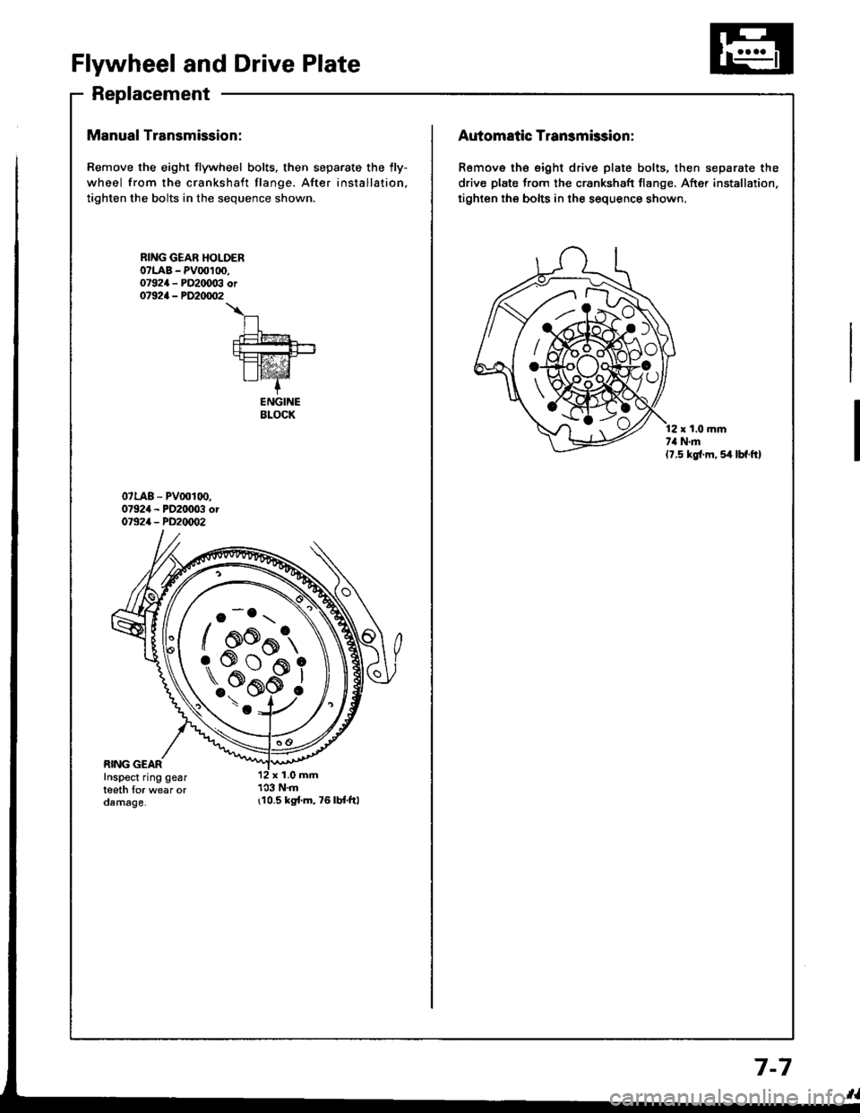
Flywheel and Drive Plate
Replacement
Manual Transmission:
Remove the eight flywheel bolts, then separate the lly-
wheel from the crankshaft flange. After installation,
tighten the bolts in the sequence shown.
r10.5 kgi.m,76lbt.ftl
RING GEAR HOLOERo?LAB - PV00100,07924 - PO2IX)03 or07924 - PD20/m�2
\
n.t=?4
fut!!-+-rt=tz-21I lvaz'Z-+
ENGINEBLOCK
o -o.r \
/ oo^t,
\..?bi
/ AK{:{AAo
rs#*ffi_9
Automatic Transmission:
Remove th€ eight drive plate bolts, then separate the
drive plate from the crankshaft flange, After installation,
tighten the bolts in the sequence shown.
r t.0 mmt,l N.m(7.5 kg{.m, 54 lbf.ft}
7-7
Page 330 of 1413

Transaxle
Clutch
Manual Transmission ......................
Automatic Transmission ..................
Differential
Manual Transmission
81881 engine
818C1 engine
Automatic Transmission ...............
Driveshafts
12-1
13-1
14-1
15-1
15-9
15-19
16-1
Page 343 of 1413

Manual Transmission
Special Toofs ............. 13-2
Maintenance
Transmission Oi1,...,........,........,.,..... 13-3
Back-up Light Switch
Replacement ......... 13-3
Transmission Assembly
Removal ..,.......,...... 13-4
lllustrated Index ................................... 13-8
Transmission Housing
Removal ...........,..... 13-10
Reverse Change Holder, Reverse ldler Gear
Glearance lnspestion ....................... 13-1 1
Removaf ................. 13-12
Change Holder Assembly
Clearance Inspection ....................... 1 3-1 3
Removal ................. 13-15
Disassembly/Reassembly ............... 13-16
Mainshaft, Gountershaft, Shift Fork
Removal ...,............. 13-17
Shift Rod
Removal ................. 13-18
Shift Fork Assembly
Index ................ ...... 13-19
Clearance Inspection ....................... 13-20
Mainshaft Assembly
Index ................ ...... 13-21
Clearance f nspection ....................... 13-22
Disassembly .......... 13-25
Inspection .............. 13-26
Reassembly ........... 13-21
Countershaft Assembly
Index ................ ...... 13-28
Clearance Inspection ....................... 13-29
Disassembly .......... 13-30
Inspection .............. 13-31
Reassembly ........... 13-32
Synchro Sleeve, Synchro Hub
Inspection .............. 13-34
Installation ............. 13-34
Synchro Ring, Gear
lnspection .............. 13-35
Clutch Housing Bearing
Replacement ......... 13-36
Mainshaft Thrust Clearance
Adiustment ............ 13-38
Transmission
Reassembly ........... 13-tl1
Transmission Assembly
lnstallation ............. 13-46
Gearshift Mechanism
Overhaul ................ 13-50
Page 395 of 1413

The Automatic Transmission is a combination of a 3-e,ement torque convefter and triple-shaft electfonically controlled
automatic transmission which provides 4 speeds forward and 1 speed reverse. The entire unit is positioned in line with
the engine.
Torque Converter, Gears and Clutches
The torque converter consists of a pump, turbine and stator assembly in a single unit, The torque converter is connected
to the engine crankshaft so they turn together as a unit as the engine turns. Around the outside of the torque converter
is a ring gear which meshes with the starter pinion when the engine is being staned. The entire torque converter assem-
bly serves as a flywheel while transmitting power to the transmission mainshaft.
The transmission has three parallel shafts, the mainshaft. countershaft and sub-shaft. The mainshatt is in line with the
engine crankshaft.
The mainshaft includes the clutches for 1 st, and 2ndl4th, and gears for 3rd. 2nd, 4th, reverse and l st (3rd gear is in-
tegral with the mainshaft, while reverse gear is integral with the 4th gear).
The countershaft includes the 3rd clutch and gears Ior 3rd, 2nd,4th, reverse, lst and parking. Reverse and 4th gears
can be locked to the countershaft at its center, providing 4th gear or reverse, depending on which way the selector is moved.
The sub-shaft includes the lst-hold clutch and gears for 1st and 4th
The gears on the mainshait are in constant mesh with those on the countershaft and sub-shaft. When certain combina-
tions of gears in the transmission are engaged by the clutches, power is transmitted from the mainshaft to the counter-
shaft via the sub-shatt to provide @, E, tr. tr and @ position.
Electronic Control
The electronic control system consists of the Transmission Control Module {TCM), sensors, and 4 solenoid valves. Shift-
ing and lock-up are electronically controlled for comfortable driving under all conditions.
The TCM is located below the dashboard, behind the left side kick panel on the driver's side.
Hydraulic Control
The valve bodies include the main valve body, secondary valve body, regulator valve body. servo body, and lock-up valve
body throuqh the respective separator plates.
They are bolted on the torque converter housing.
The main valve body contains the manual valve, 1-2 shift valve, 2-3 shift valve, Clutch Pressure Cont.ol (CPC) valve,
4th exhaust valve, relief valve, and oil pump gears.
The secondary valve body contains the 4-3 kick-down valve,3-2 kick-down valve,2-3 orifice cont.ol valve, 3-4 shitt
valve, orifice control valve. modulator valve, and servo control valve
The regulator valve body contains the pressure regulator valve. lock-up control valve, torque converter check valve, and
cooler check valve.
The servo bodv contains the servo valve which is integrated with the reverse shift fork, throttle valve B, and accumulators.
The lock-ug valve bodv contains the lock-up shift valve and lock-up timing B valve. and is bolted on the secondary valve
body.
Fluid from the regulator passes through the manual valve to the various control valves.
Shitt Control Mochanism
Input to the TCM i.om various sensors located throughout the car determines which shift control solenoid valve should
be activated.
Activating a shift control solenoid valve changes modulator pressure, causing a shift valve to move. This pressurizes
a line to one of the clutches. engaging that clutch and its corresponding gear.
Lock-up Mechanism
In @ position. in 2nd, 3rd and 4th, and E position in 3rd, pressurized tluid can be drained from the back of the tor-
que converter through an oil passage, causing the lock-up piston to be held against the torque converter cover. As this
takes Dlace, the mainshaft rotates at the same speed as the engine crankshatt. Together with hydraulic control, the TCM
optimizes the timing ol the lock-up mechanism.
The lock-up valves control the range of lock-up according to lock-up control solenoid valves A and B, and throttle valve B
When lock-up control solenoid valves A and B activate, modulator pressure changes. Lock-up control solenoid valves
A and B are mounted on the torque converter housing, and are controlled by the TCM.
(cont'd)
14-3
Page 478 of 1413

Symptom-to-Component Chart
Hydraulic System
SYMPTOMCheck these items on the
PROBABLE CAUSE ListCheck these items
on the NOTES List
Engine runs, but car does not move in any gear.1, 6, 7, 16K,L,R,S
Car moves in @ and @, but not in @, @ or Iposataon.a, 29, 44. 4ac,M,o
Car moves in E, @, [, @, uut not in E position.9,30,49C, L
car moves in p:1, [o-il, [2-], [!, uut not in E position.1, 11, 22, 34, 38, 39, 40c,L,o
Car moves in N position.1, 8, 9, 10, 11,46,47C,D
Excessive idle vibration.5, 1'1B,K,L
Slips in all gears.6, 7, 16C,L
No engine braking in E position.12C,D,L
Slips in 1st gear.8, 29, 44, 4Ac,N,o
Slips in 2nd gear.9, 20, 23, 30, 49C, L
Slips in 3rd gear.10, 21 , 23, 31 , 49C,L
Slips in 4th gear.11, 23, 32, 44C,L,N
Slips in reverse gear.11,32,34,44C,N
Flares on 1-2 upshilt.3, 15, 23E,L,V
Flareson2 3 upshilt.3, 15, 23, 24, 49E,L,V
Flares on 3-4 upshift.3, 15, 23, 25, 49E,L,N,V
No upshift; transmission stays in 1st gear.14,19,G, L
No downshift to lst gear.12. 19G, L
Late upshift.14
Erratic shitting.2, 14,26
Harsh shift (up and down shiftingl.2, 4, 15, 23, 24, 25, 26, 27,
47A,E, H, I, L,V
Harsh shitt {1-2).2, 9. 15, 23C,D,E,V
Harshshilt (2-3).2, 10, 15, 23, 24C,D,E,H,L,V
Harsh shift (3-4).2,| 1, 15, 23, 25C, D, E, I,L,V
Harsh kick'down shifts.2, 15, 23, 26, 27. 2AE,L,O,V
Harsh kick-down shift 12 1)48o
Harsh downshift at closed throttle.2, 15, 23FT
Harsh shift when manually shifting to E] position.33L
Axle{s} slips out of transmission on turns.43,50
Axlels) stuck in transmission.43L,O
Ratcheting noise when shifting inro E position.6,7,38,39,40K,L,O
Loud popping noise when taking ott in E position.3a,39,40L,O
Ratcheting noise when shifting from E to E position or from Eto N I oosition.38,33,40,45L,O
Noise from transmission in all selector lever positions.6, 11K,L,O
Noise trom transmission only when wheels are rolling.39, 42L,O
Gear whine, rpm related (pitch changes with shitts).a, 13, 41K,L,O
Gear whine, speed rel6ted (pitch changes with speed).38, 42L,O
Transmission will not shift into 4th gear in @ position1,21,24.32L
Lock-up clutch does not lock-up smoothly.17, 36, 37L
Lock-up clutch does not operate properlV.2.3. 14, 15. 18, 35, 36, 37E,L,V
Transmission has multitude of problems shitting.
At disassembly, large particles oI metal are found on magnet.43L,O
14-86
Page 481 of 1413

NOTES
A.See flushing procedure, page l4-168 and 169.
B.Set idle rpm in gear to specitied idle speed. lf still no good, adiust motor mounts as outlined in engine
section of service manual.
lf the large clutch piston O-ring is broken, inspect the piston groove for rough machining.
lf the clutch pack is seized or is excessively worn, inspect the other clutches Jor wear, and check the
orifice control valves and throttle valves for free movement.
E.It throttle valve B is stuck, inspect the clutches for wear.
lf the 1-2 shift valve is stuck closed, the transmission will not upshift. lI stuck open, the transmission
has no lst gear.
H.lf the 2-3 orifice control valve is stuck, inspect the 2nd and 3rd clutch packs for wear.
ll the orifice cont.ol valve is stuck, inspect the 3rd and 4th clutch packs for wear.
lf the clutch Dressure control valve is stuck closed, the transmission will not shilt out of 1st gear.
K.improper alignment or main valve body and torque converter housing may cause oil pump seizure. The
symptoms ale mostly an rpm-related ticking noise or a high-pitched squeak.
L.ll the ATF strainer is ctogged with panicles of steel or aluminum, inspect the oil pump and ditferential
pinion shaft. lt both are OK and no cause lor the contamination is found, replace the torque converter.
M.lf the 1st clutch feedpipe guide in the right side cover is scored by the mainshaft, inspect the ball bear-
ing for excessive movement in the transmission housing. lf OK. replace the right side cover as it is dent-
ed. The O-ring under the guide is probably worn.
N.ReDlace the mainshstt if the bushing for the 4th feedpipe is loose or damaged.
It the 4th feedpipe is damaged or out ot tound, replace the right side cover'
Replace the subjshaft it thtbushing for the 1st-hold Jeedpipe is loose or damaged.
lf the 1st-hold feedpipe is damaged or out of round, replace it.
Replace the mainshaft if the bushing lor the 1st feedpipe is loose or damaged.
lf the lst feedpipe is damaged or out ot round, replace it.
o.A *o- r, da."s"d "p-g clutch is mostly a result of shifting the transmission in El or Lq! position
while the wheels rotate in reverse, such as rocking the car in snow.
P.InsDect the frame for collision damage.
o.Inspect for damage or wear:
1. Reverse selector gear teeth chamfers.
2. Engagement teeth chamters of countershaft 4th and reverse gear.
3. Shift fork for scutt marks in center.
4. Differential Dinion shaJt for wear under pinion gears.
5. Bottom of 3rd clutch for switl marks.
Replace items 1 , 2, 3 and 4 it worn or damaged. lf transmission makes clicking, grinding or.whirring
noise, atso replace mainshaft 4th gear and reverse idler gear and countershaft 4th gear in addition to
1,2,3ot4.lf ditiersntial Dinion shaft is worn, overhaul differential assembly, and replace ATF strainel, and thoroughly
clean transmission, tlush torque convertet, cooler and lines.
lf bottom of 3rd clutch is swirled and transmission makes gear noise, replace the countershaft and tinal
driven gear.
R.Be wry careful not to dsmage the torque converter housing when replacing the main ballbearing. You
may al;o damage the oil pump when you torque down the main valve body. This will result in oil pump
seizure it not detected. Use proper tools.
qInstall the main seal tlush with the torque converter housing, lf you push it into the torque converter
housing until it bottoms out. it will block the oil return passage and result in damage.
T,Harsh do\/vnshiJt"\./l,'hen coasting to a stop with zero th.ottle may be caused by a bent-in throttle valve
retainer/cam stopper. Throttle cable adjustment may clear this problem.
ifuitle cable adjustment is essential for proper operation of the transmission. Not only does it affect
the shift points if misad,usted, but also the shift quality and lock-up clutch operation'
A cable adjusted too long will result in throttle pressure being too low for the amount of engine torque
input into ihe trsnsmission and may cause clutch slippage. A cable adjusted too short will result in too
hi;h throttle pressure which may cause harsh shitts, erratic shrfts and torque con
14-89
Page 567 of 1413

Differential
Manual Transmission
81881 engine
818C1 engine .......
Automatic Transmission ..................
15-1
15-9
15-19