Page 1157 of 1254
HEADLAMP
-
Headlamp Aiming Control-
EL.45
Page 1158 of 1254
HEADLAMP
-
Headlamp Aiming
Control-
/:\6
o *#l
e -{-rl
Wiring
Diagram
,a I )'+t' I
\? *'Ha
l
c
E^
f oc
---t-
^/A
€lo
=
o
zu
n
:
Lrn
-Ll
6
i; L-l
tr
o
!
.
a
!
-
EL47
Page 1159 of 1254
HEADLAMP
-
Headlamp Aiming
Control-
A Cil
Lighting swrlch lsl
5r
ts EI'H)
mtri
mti Troublediagnoses
SYMPTOM: Headlamp
aiming does not operate.
E
Check 10A fse
al luse
block.
(Refer to "POWER
SUPPLY
ROUTING.")
POWER
SUPPLY CIRCUIT
CHECK (For
aiming switch)
Check if
12 volts
exist between
terminals O and
aO.
AIMING SWITCH CHECK
Check continuity between termi-
nals at each switch position.
GROUND CIRCUIT
CHECK
FOR AIMING MOTOR
Check continuity between termi-
nals rj)
and body grround.
Continuity exists ... O.K. Bepair
harness between
aiming
motor and body ground.
POWER SUPPLY CIRCUIT
CHECK
(For aiming motor unit)
Check il 12 volts
exist between
terminats 'O,
@, @, @ and
o Volt-
meter
termina Voltage
[V]Aiming
switch
posrtron
o Approx.
12"0"
o "0"
.;\ Approx.
12"1"
0 "1"
o Approx.
12
0
o Approx.
12,.3,,
0 "3"Check
harness
between aimjng
switch and aiming motor
unit.
EL.48
Page 1160 of 1254

HEADLAMP
PUSH Io
\
_@. PUSH
lo Bulb
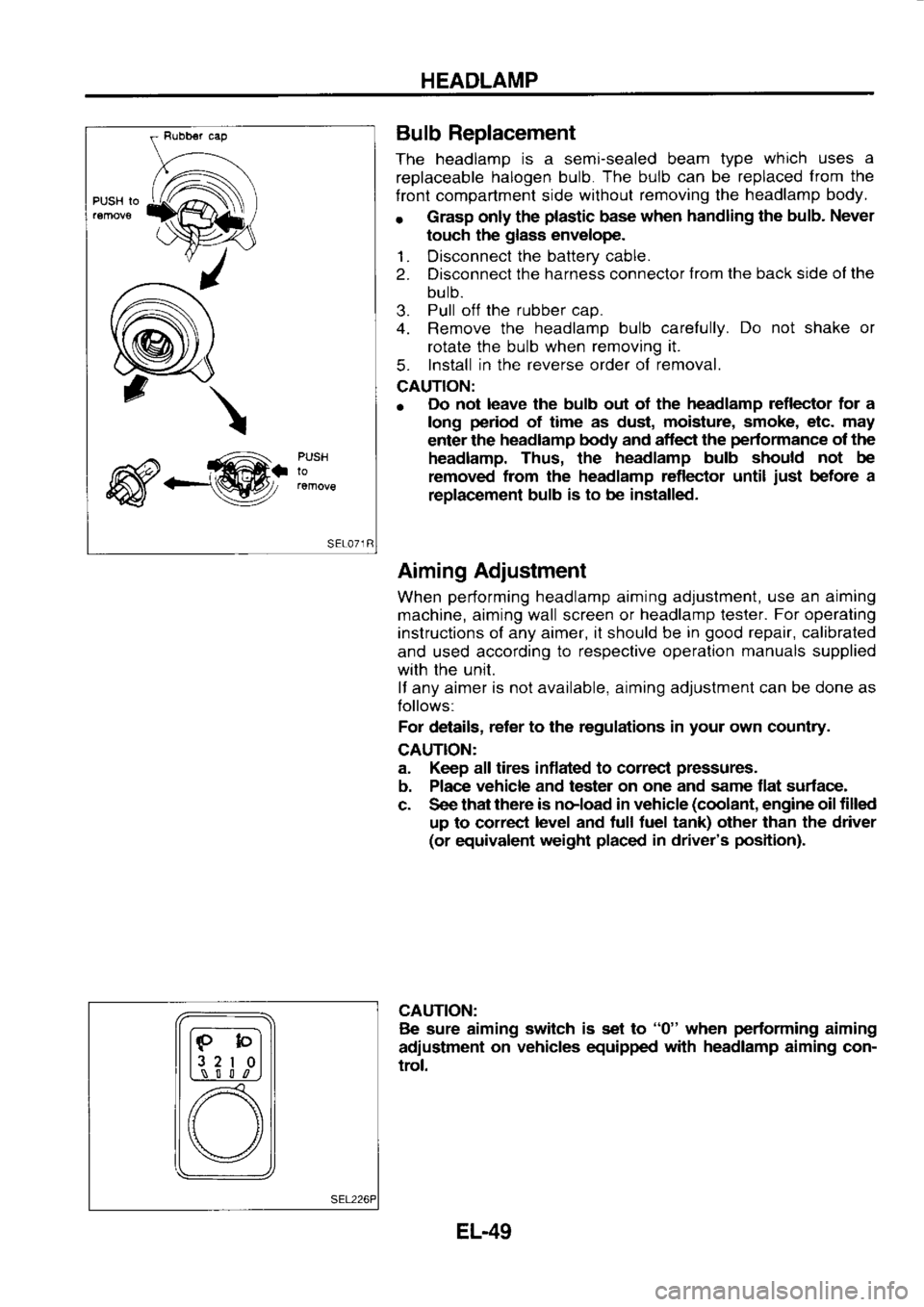
Replacement
The headlamp is
a semi-sealed beam type which
uses a
replaceable halogen
bulb. The
bulb can
be replaced from
the
f ront compartment side without
removing the headlamp
body.
r Grasp
only the plastic
base when
handling the bulb.
Never
touch the glass
envelope.
1. Disconnect the
battery cable.
2. Disconnect the
harness connector from
the back side ol the
bulb.
3. Pull
off the
rubber cap.
4. Remove the headlamp
bulb carefully. Do
not shake or
rotate the bulb when removing it.
5. Install
in the reverse
order of removal.
CAUTION:
o Do
not leave the bulb out of the headlamp
reflector for a
long period
of time as dust, moisture,
smoke, etc. may
enter the headlamp
body and aflect the pedormance
of the
headlamp. Thus, the headlamp
bulb should not
be
removed from
the headlamp reflector until just
before a
replac€ment bulb is
to be installed.
Aiming Adjustment
When performing
headlamp aiming adjustment, use
an aiming
machine, aiming wall screen or headlamp
lester. For
operating
instructions of any aimer, it should be in good
repair, calibrated
and used according to
respective operation manuals
supplied
with the unit.
lf any aimer is
not available, aiming adjustment can be done as
Iollows:
For details, reter
to the regulations in your
own country.
CAUTION:
a. Keep all tires inflated to correcl pressures.
b. Place vehicle
and tester on one
and same flat surface-
c. See that there
is noload in vehicle (coolant,
engine oil filled
up to correct level
and tull tuel tank) other than the driver
(or equivalent weight placed
in driver's position).
CAUTION: Be sure aiming switch
is set to "0"
when performing
aiming
adiustment on
vehicles equipped with
headlamp
aiming con-
trol.
lF-bl
l3 2
I 0l
L,\_-! S l l
,n
[) \/
EL-49
Page 1161 of 1254
HEADLAMP
lJp and down adlustrng Aiming
Adjustment (Cont'd)
LOW BEAM
1 . Turn
headlamp low beam on.
2. Use adjusting screws lo perform
aiming adjustment.
o First
tighten the adiusting screw
all the way and then make
adiustment by loosening the screw.
a. Adiust
headlamps so that main axis of light is parallel
to
center line ol body and is aligned with point
P shown in
illustration.
b. Figure to the left shows headlamp aiming pattern
for driv-
ing on right
side of road;
for
driving on left side of road,
aiming pattern
is reversed.
c. Dotted
lines in illustration show c€nter of headlamp.
"H": Horizontal c€nter line of headlamps
"W.": Distanc€ between each headlamp
center
"L": 5,fi)O mm (196.85
in)
"C": 53 mm (2.09
in)
Varticalcantgrlane
ahrsd of haedlamp, Heighr
ol -
q$ =
acceenere nrruce
EL-50
Page 1174 of 1254

EXTERIOR
LAMP
Tesr lamg (27W1
8a(ery Combination
Flasher
Unit Check
. Before
checking, ensure that bulbs meet specifications.
o Connect
a battery
and test lamp
to the combination
flasher
unit, as shown. Combination flasher unit is properly
lunc-
tioning if it
blinks when power
is supplied to the circuit.
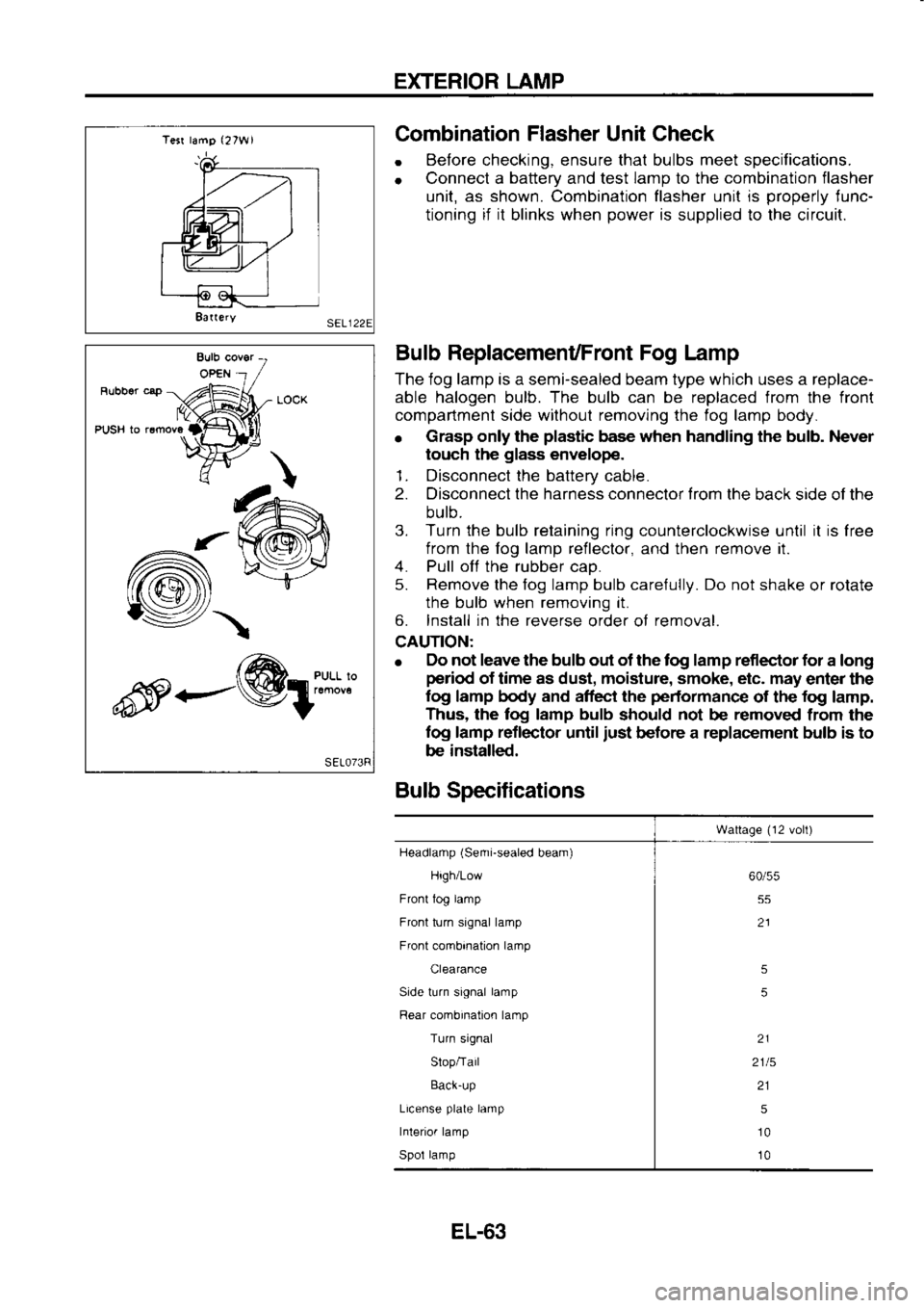
Bulb ReplacemenUFront Fog Lamp
The iog lamp is a semi-sealed beam type which uses a replace-
able halogen bulb. The bulb can be replaced from the front
compartment side withoul removing the fog lamp body.
o Grasp
only the plastic
base when handling the bulb. Never
touch the glass
envelope.
1. Disconnect the battery
cable.
2. Disconnect the harness connector trom
the back side of the
bulb.
3. Turn the bulb retaining ring
counterclockwise until it
is
free
from the fog lamp reileclor,
and then remove
it.
4. Pull off
the rubber
cao.
5. Remove
the fog lamp bulb care{ully. Do not
shake or rolate
the bulb when removing it.
6. Install in the reverse
order of removal.
CAUTION:
e Elo
not leave the bulb out of the tog lamp reflector for
a long
period of time as dust, moisture, smoke, etc. may
enter the
log lamp body and affect the performance
of the fog
lamp.
Thus, the log lamp bulb
should not
be removed
from the
fog lamp reflector
until just
before a replacement bulb is to
be installed.
Bulb Specifications
Wattage (12
volt)
Headlamp (Semi-sealed
beam)
High/Low
Front tog lamp
Front turn signal lamp
Front combination lamp
Clearance
Side turn signal lamp
Rear combination lamp
Turn signal
Slop/Tail
Back-up
License plate
lamp
Interior lamp
Spol lamp 60/55
55
21
5
5
21
2115 215
10
10
-/\
<---@1:"*:l'l
EL-63
Page 1197 of 1254
WIPER
AND WASHER
Headlamp Wiper
and WasherAViring Diagram
I ')',)
=o
99
9l,]!
333
DoraDl' I i€,P;
9QE{qq
5 3,? 5 r
c
UropL].]p
L-rooco
ro
i um i.at
ion
{
s y
slem
cl
t=, (ot
i a (c
G .t
-!"!'")
NIFI
+r .
L
,tl
\-,
B.:to|] 0
c oc
G]
\:/
I T-T
oll
tr? t_.1
!= ;
EL.86
Page 1198 of 1254
WIPER
AND WASHER
Headlamp Wiper Motor
Check
When wiper motor
is locked, a protective
circuit built into
wiper
motor activates to
stop wiper
motor.
lf wiper motor will not
restart even after cause of problems
has been eliminated, turn
ignition swilch
OFF and leave it off for approx. 1 to 3 minutes.
'| . Turn headlamo wioer switch OFF.
2. Connect ohmmeter
and check continuitv.
Headlamp Wiper Installation
Tighten nut
to secure wiper
arm with
wiper blade held
below-
rower sloooer.
After installing wiper
arm, position
wiper blade on slopper
upper
surface.
o Tighten
headlamp wiper
arm nut
to the specifierd
torque.
pl: 2.9 -
4.4 N.m
(0.30 -
0.45 kg-m, 2.2 -
3.3 ftlb)
Headiamp
wrper
molor Ohmrneler
probe
Conlrnurly
() ()
Stop position J
J .3_ Yes
Yes
Yes No
p /z.s
- ..n i"'
(0.30 -
0.45 kg-m,
I | 2.2
-,
3.3 trrbl
E1.87