1993 FORD MONDEO weight
[x] Cancel search: weightPage 167 of 279
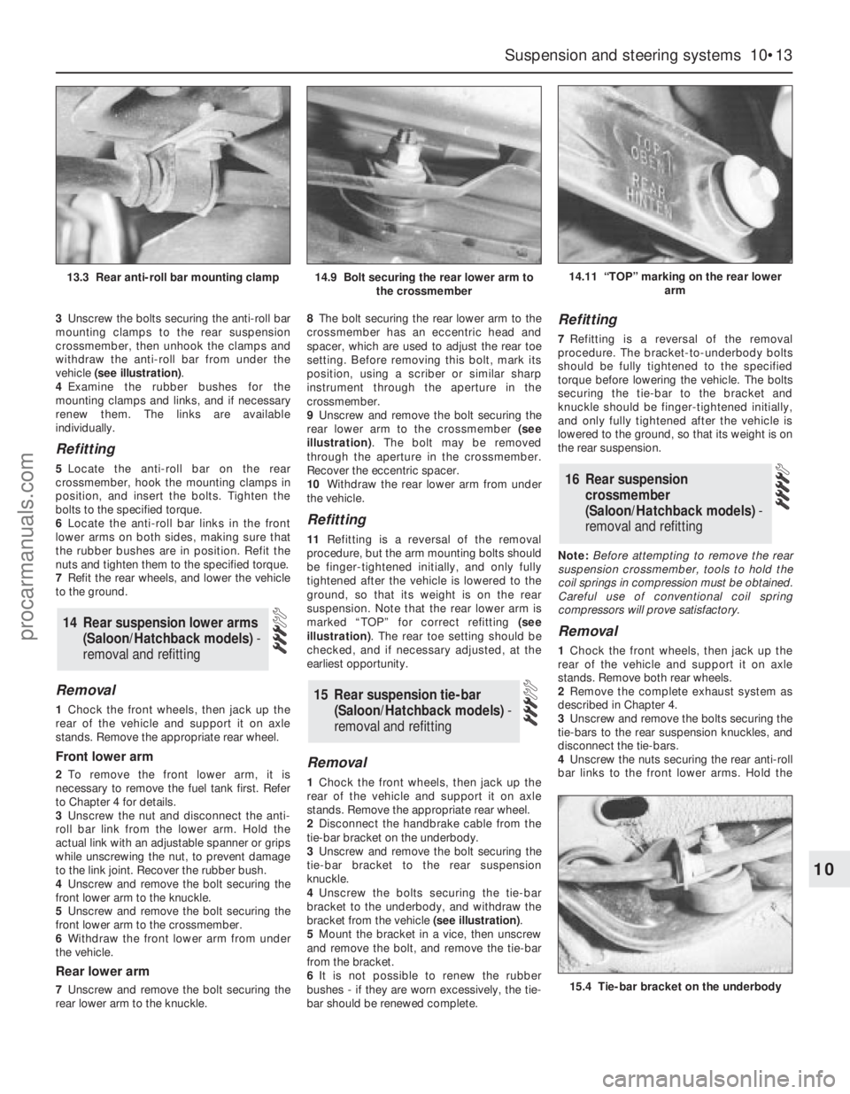
3Unscrew the bolts securing the anti-roll bar
mounting clamps to the rear suspension
crossmember, then unhook the clamps and
withdraw the anti-roll bar from under the
vehicle (see illustration).
4Examine the rubber bushes for the
mounting clamps and links, and if necessary
renew them. The links are available
individually.
Refitting
5Locate the anti-roll bar on the rear
crossmember, hook the mounting clamps in
position, and insert the bolts. Tighten the
bolts to the specified torque.
6Locate the anti-roll bar links in the front
lower arms on both sides, making sure that
the rubber bushes are in position. Refit the
nuts and tighten them to the specified torque.
7Refit the rear wheels, and lower the vehicle
to the ground.
Removal
1Chock the front wheels, then jack up the
rear of the vehicle and support it on axle
stands. Remove the appropriate rear wheel.
Front lower arm
2To remove the front lower arm, it is
necessary to remove the fuel tank first. Refer
to Chapter 4 for details.
3Unscrew the nut and disconnect the anti-
roll bar link from the lower arm. Hold the
actual link with an adjustable spanner or grips
while unscrewing the nut, to prevent damage
to the link joint. Recover the rubber bush.
4Unscrew and remove the bolt securing the
front lower arm to the knuckle.
5Unscrew and remove the bolt securing the
front lower arm to the crossmember.
6Withdraw the front lower arm from under
the vehicle.
Rear lower arm
7Unscrew and remove the bolt securing the
rear lower arm to the knuckle.8The bolt securing the rear lower arm to the
crossmember has an eccentric head and
spacer, which are used to adjust the rear toe
setting. Before removing this bolt, mark its
position, using a scriber or similar sharp
instrument through the aperture in the
crossmember.
9Unscrew and remove the bolt securing the
rear lower arm to the crossmember (see
illustration). The bolt may be removed
through the aperture in the crossmember.
Recover the eccentric spacer.
10Withdraw the rear lower arm from under
the vehicle.
Refitting
11Refitting is a reversal of the removal
procedure, but the arm mounting bolts should
be finger-tightened initially, and only fully
tightened after the vehicle is lowered to the
ground, so that its weight is on the rear
suspension. Note that the rear lower arm is
marked “TOP” for correct refitting (see
illustration). The rear toe setting should be
checked, and if necessary adjusted, at the
earliest opportunity.
Removal
1Chock the front wheels, then jack up the
rear of the vehicle and support it on axle
stands. Remove the appropriate rear wheel.
2Disconnect the handbrake cable from the
tie-bar bracket on the underbody.
3Unscrew and remove the bolt securing the
tie-bar bracket to the rear suspension
knuckle.
4Unscrew the bolts securing the tie-bar
bracket to the underbody, and withdraw the
bracket from the vehicle (see illustration).
5Mount the bracket in a vice, then unscrew
and remove the bolt, and remove the tie-bar
from the bracket.
6It is not possible to renew the rubber
bushes - if they are worn excessively, the tie-
bar should be renewed complete.
Refitting
7Refitting is a reversal of the removal
procedure. The bracket-to-underbody bolts
should be fully tightened to the specified
torque before lowering the vehicle. The bolts
securing the tie-bar to the bracket and
knuckle should be finger-tightened initially,
and only fully tightened after the vehicle is
lowered to the ground, so that its weight is on
the rear suspension.
Note:Before attempting to remove the rear
suspension crossmember, tools to hold the
coil springs in compression must be obtained.
Careful use of conventional coil spring
compressors will prove satisfactory.
Removal
1Chock the front wheels, then jack up the
rear of the vehicle and support it on axle
stands. Remove both rear wheels.
2Remove the complete exhaust system as
described in Chapter 4.
3Unscrew and remove the bolts securing the
tie-bars to the rear suspension knuckles, and
disconnect the tie-bars.
4Unscrew the nuts securing the rear anti-roll
bar links to the front lower arms. Hold the
16 Rear suspension
crossmember
(Saloon/Hatchback models) -
removal and refitting
15 Rear suspension tie-bar
(Saloon/Hatchback models) -
removal and refitting
14 Rear suspension lower arms
(Saloon/Hatchback models)-
removal and refitting
Suspension and steering systems 10•13
10
14.11 “TOP” marking on the rear lower
arm
15.4 Tie-bar bracket on the underbody
13.3 Rear anti-roll bar mounting clamp14.9 Bolt securing the rear lower arm to
the crossmember
procarmanuals.com
Page 168 of 279
actual links stationary while the nuts are being
unscrewed, to prevent damage to the joints.
Swivel the anti-roll bar upwards, and recover
the rubber bushes.
5Where applicable, remove the ABS wheel
sensor from the rear suspension knuckle as
described in Chapter 9.
6Unscrew and remove the bolts, and
disconnect both lower arms from the rear
suspension knuckle.
7To allow the rear suspension struts to be
released from the rubber stops on the top of
the crossmember, it is necessary to fit coil
spring compressor tools to both of the rear
coil springs, and compress them until all
tension is removed from the upper and lower
mountings.
Warning: It is important to only
use high-quality spring
compressors, and to carefully
follow the tool manufacturer’s
instructions provided with them. With the
compressor tools fitted, support the struts
to one side.
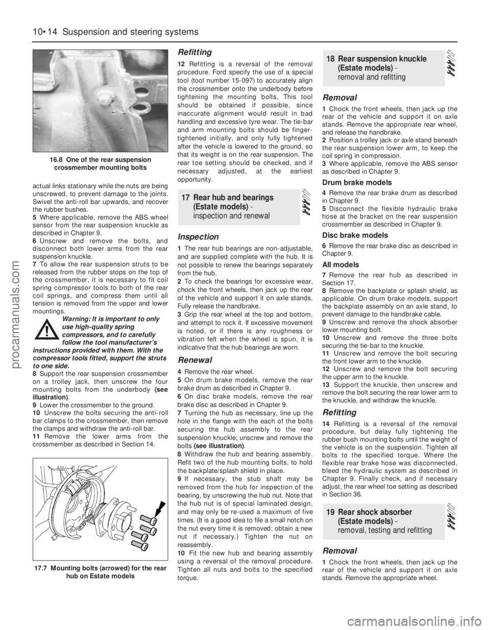
8Support the rear suspension crossmember
on a trolley jack, then unscrew the four
mounting bolts from the underbody (see
illustration).
9Lower the crossmember to the ground.
10Unscrew the bolts securing the anti-roll
bar clamps to the crossmember, then remove
the clamps and withdraw the anti-roll bar.
11Remove the lower arms from the
crossmember as described in Section 14.
Refitting
12Refitting is a reversal of the removal
procedure. Ford specify the use of a special
tool (tool number 15-097) to accurately align
the crossmember onto the underbody before
tightening the mounting bolts. This tool
should be obtained if possible, since
inaccurate alignment would result in bad
handling and excessive tyre wear. The tie-bar
and arm mounting bolts should be finger-
tightened initially, and only fully tightened
after the vehicle is lowered to the ground, so
that its weight is on the rear suspension. The
rear toe setting should be checked, and if
necessary adjusted, at the earliest
opportunity.
Inspection
1The rear hub bearings are non-adjustable,
and are supplied complete with the hub. It is
not possible to renew the bearings separately
from the hub.
2To check the bearings for excessive wear,
chock the front wheels, then jack up the rear
of the vehicle and support it on axle stands.
Fully release the handbrake.
3Grip the rear wheel at the top and bottom,
and attempt to rock it. If excessive movement
is noted, or if there is any roughness or
vibration felt when the wheel is spun, it is
indicative that the hub bearings are worn.
Renewal
4Remove the rear wheel.
5On drum brake models, remove the rear
brake drum as described in Chapter 9.
6On disc brake models, remove the rear
brake disc as described in Chapter 9.
7Turning the hub as necessary, line up the
hole in the flange with the each of the bolts
securing the hub assembly to the rear
suspension knuckle; unscrew and remove the
bolts (see illustration).
8Withdraw the hub and bearing assembly.
Refit two of the hub mounting bolts, to hold
the backplate/splash shield in place.
9If necessary, the stub shaft may be
removed from the hub for inspection of the
bearing, by unscrewing the hub nut. Note that
the hub nut is of special laminated design,
and may only be re-used a maximum of five
times. (It is a good idea to file a small notch on
the nut every time it is removed; obtain a new
nut if necessary.) Tighten the nut on
reassembly.
10Fit the new hub and bearing assembly
using a reversal of the removal procedure.
Tighten all nuts and bolts to the specified
torque.
Removal
1Chock the front wheels, then jack up the
rear of the vehicle and support it on axle
stands. Remove the appropriate rear wheel,
and release the handbrake.
2Position a trolley jack or axle stand beneath
the rear suspension lower arm, to keep the
coil spring in compression.
3Where applicable, remove the ABS sensor
as described in Chapter 9.
Drum brake models
4Remove the rear brake drum as described
in Chapter 9.
5Disconnect the flexible hydraulic brake
hose at the bracket on the rear suspension
crossmember as described in Chapter 9.
Disc brake models
6Remove the rear brake disc as described in
Chapter 9.
All models
7Remove the rear hub as described in
Section 17.
8Remove the backplate or splash shield, as
applicable. On drum brake models, support
the backplate assembly on an axle stand, to
prevent damage to the handbrake cable.
9Unscrew and remove the shock absorber
lower mounting bolt.
10Unscrew and remove the three bolts
securing the tie-bar to the knuckle.
11Unscrew and remove the bolt securing
the front lower arm to the knuckle.
12Unscrew and remove the bolt securing
the upper arm to the knuckle.
13Support the knuckle, then unscrew and
remove the bolt securing the rear lower arm to
the knuckle, and withdraw the knuckle.
Refitting
14Refitting is a reversal of the removal
procedure, but delay fully tightening the
rubber bush mounting bolts until the weight of
the vehicle is on the suspension. Tighten all
bolts to the specified torque. Where the
flexible rear brake hose was disconnected,
bleed the hydraulic system as described in
Chapter 9. Finally check, and if necessary
adjust, the rear wheel toe setting as described
in Section 36.
Removal
1Chock the front wheels, then jack up the
rear of the vehicle and support it on axle
stands. Remove the appropriate wheel.
19 Rear shock absorber
(Estate models) -
removal, testing and refitting
18 Rear suspension knuckle
(Estate models) -
removal and refitting
17 Rear hub and bearings
(Estate models) -
inspection and renewal
10•14 Suspension and steering systems
16.8 One of the rear suspension
crossmember mounting bolts
17.7 Mounting bolts (arrowed) for the rear
hub on Estate models
procarmanuals.com
Page 169 of 279
2Position a trolley jack under the coil spring
area of the rear lower suspension arm, to
keep the coil spring in compression.
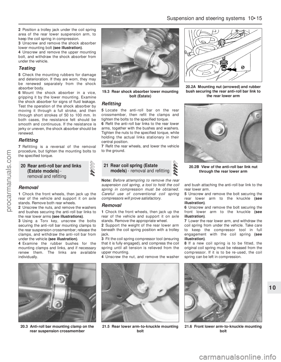
3Unscrew and remove the shock absorber
lower mounting bolt (see illustration).
4Unscrew and remove the upper mounting
bolt, and withdraw the shock absorber from
under the vehicle.
Testing
5Check the mounting rubbers for damage
and deterioration. If they are worn, they may
be renewed separately from the shock
absorber body.
6Mount the shock absorber in a vice,
gripping it by the lower mounting. Examine
the shock absorber for signs of fluid leakage.
Test the operation of the shock absorber by
moving it through a full stroke, and then
through short strokes of 50 to 100 mm. In
both cases, the resistance felt should be
smooth and continuous. If the resistance is
jerky or uneven, the shock absorber should be
renewed.
Refitting
7Refitting is a reversal of the removal
procedure, but tighten the mounting bolts to
the specified torque.
Removal
1Chock the front wheels, then jack up the
rear of the vehicle and support it on axle
stands. Remove both rear wheels.
2Unscrew the nuts, and remove the washers
and bushes securing the anti-roll bar links to
the rear lower arms (see illustrations).
3Using a Torx key, unscrew the bolts
securing the anti-roll bar mounting clamps to
the rear suspension crossmember; release the
clamps, and withdraw the anti-roll bar from
under the vehicle (see illustration).
4Examine the rubber bushes for the
mounting clamps and links, and if necessary
renew them. The links are available
individually.
Refitting
5Locate the anti-roll bar on the rear
crossmember, then refit the clamps and
tighten the bolts to the specified torque.
6Refit the anti-roll bar links to the rear lower
arms, together with the bushes and washers.
Tighten the nuts to the specified torque, while
holding the actual links stationary in their
central position.
7Refit the rear wheels, and lower the vehicle
to the ground.
Note:Before attempting to remove the rear
suspension coil spring, a tool to hold the coil
spring in compression must be obtained.
Careful use of conventional coil spring
compressors will prove satisfactory.
Removal
1Chock the front wheels, then jack up the
rear of the vehicle and support it on axle
stands. Remove the appropriate wheel.
2Support the weight of the rear lower arm
beneath the coil spring position with a trolley
jack.
3Fit the coil spring compressor tool (ensuring
that it is fully engaged), and compress the coil
spring until all tension is relieved from the
upper mounting.
4Unscrew the nut, and remove the washerand bush attaching the anti-roll bar link to the
rear lower arm.
5Unscrew and remove the bolt securing the
rear lower arm to the knuckle (see
illustration).
6Unscrew and remove the bolt securing the
front lower arm to the knuckle (see
illustration).
7Lower the rear lower arm, and withdraw the
coil spring from under the vehicle. Take care
to keep the compressor tool in full
engagement with the coil spring (see
illustration).
8If a new coil spring is to be fitted, the
original coil spring must be released from the
compressor. If it is to be re-used, the coil
spring can be left in compression.
21 Rear coil spring (Estate
models) - removal and refitting20 Rear anti-roll bar and links
(Estate models) -
removal and refitting
Suspension and steering systems 10•15
10
20.3 Anti-roll bar mounting clamp on the
rear suspension crossmember21.5 Rear lower arm-to-knuckle mounting
bolt21.6 Front lower arm-to-knuckle mounting
bolt
19.3 Rear shock absorber lower mounting
bolt (Estate)20.2A Mounting nut (arrowed) and rubber
bush securing the rear anti-roll bar link to
the rear lower arm
20.2B View of the anti-roll bar link nut
through the rear lower arm
procarmanuals.com
Page 170 of 279
Refitting
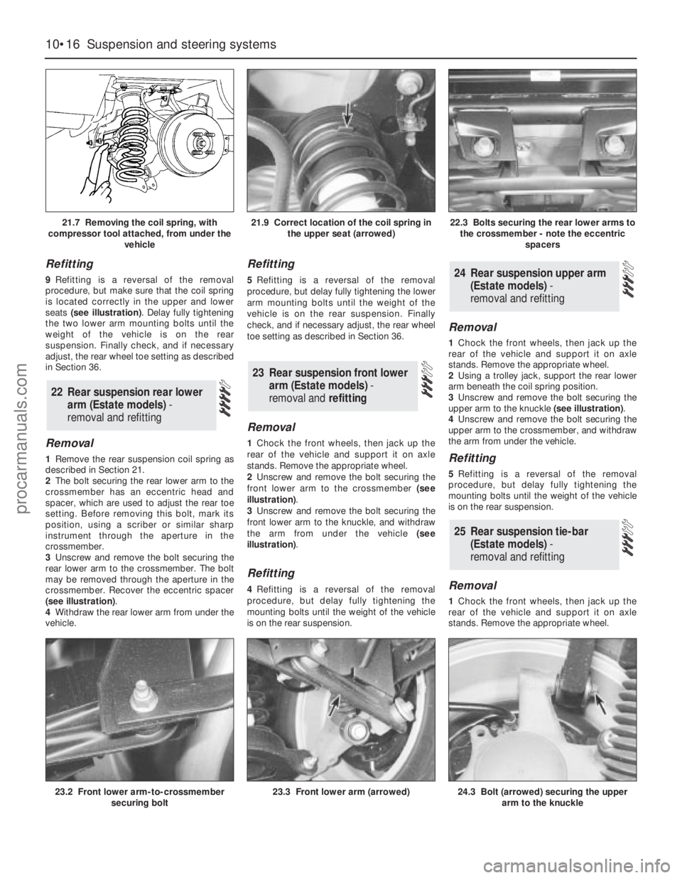
9Refitting is a reversal of the removal
procedure, but make sure that the coil spring
is located correctly in the upper and lower
seats (see illustration). Delay fully tightening
the two lower arm mounting bolts until the
weight of the vehicle is on the rear
suspension. Finally check, and if necessary
adjust, the rear wheel toe setting as described
in Section 36.
Removal
1Remove the rear suspension coil spring as
described in Section 21.
2The bolt securing the rear lower arm to the
crossmember has an eccentric head and
spacer, which are used to adjust the rear toe
setting. Before removing this bolt, mark its
position, using a scriber or similar sharp
instrument through the aperture in the
crossmember.
3Unscrew and remove the bolt securing the
rear lower arm to the crossmember. The bolt
may be removed through the aperture in the
crossmember. Recover the eccentric spacer
(see illustration).
4Withdraw the rear lower arm from under the
vehicle.
Refitting
5Refitting is a reversal of the removal
procedure, but delay fully tightening the lower
arm mounting bolts until the weight of the
vehicle is on the rear suspension. Finally
check, and if necessary adjust, the rear wheel
toe setting as described in Section 36.
Removal
1Chock the front wheels, then jack up the
rear of the vehicle and support it on axle
stands. Remove the appropriate wheel.
2Unscrew and remove the bolt securing the
front lower arm to the crossmember (see
illustration).
3Unscrew and remove the bolt securing the
front lower arm to the knuckle, and withdraw
the arm from under the vehicle (see
illustration).
Refitting
4Refitting is a reversal of the removal
procedure, but delay fully tightening the
mounting bolts until the weight of the vehicle
is on the rear suspension.
Removal
1Chock the front wheels, then jack up the
rear of the vehicle and support it on axle
stands. Remove the appropriate wheel.
2Using a trolley jack, support the rear lower
arm beneath the coil spring position.
3Unscrew and remove the bolt securing the
upper arm to the knuckle (see illustration).
4Unscrew and remove the bolt securing the
upper arm to the crossmember, and withdraw
the arm from under the vehicle.
Refitting
5Refitting is a reversal of the removal
procedure, but delay fully tightening the
mounting bolts until the weight of the vehicle
is on the rear suspension.
Removal
1Chock the front wheels, then jack up the
rear of the vehicle and support it on axle
stands. Remove the appropriate wheel.
25 Rear suspension tie-bar
(Estate models) -
removal and refitting
24 Rear suspension upper arm
(Estate models) -
removal and refitting
23 Rear suspension front lower
arm (Estate models)-
removal and refitting
22 Rear suspension rear lower
arm (Estate models) -
removal and refitting
10•16 Suspension and steering systems
21.7 Removing the coil spring, with
compressor tool attached, from under the
vehicle21.9 Correct location of the coil spring in
the upper seat (arrowed)22.3 Bolts securing the rear lower arms to
the crossmember - note the eccentric
spacers
23.2 Front lower arm-to-crossmember
securing bolt23.3 Front lower arm (arrowed)24.3 Bolt (arrowed) securing the upper
arm to the knuckle
procarmanuals.com
Page 171 of 279
2Using a trolley jack, support the rear lower
arm beneath the coil spring position.
3Unscrew and remove the bolt securing the
rear shock absorber to the knuckle.
4Where applicable, release the ABS wheel
sensor lead from the tie-bar.
5Detach the handbrake cable from the tie-
bar bracket.
6Refer to Chapter 9, and disconnect the
handbrake cable from the rear brake shoes or
rear caliper, as applicable. Pass the cable
through the hole in the tie-bar.
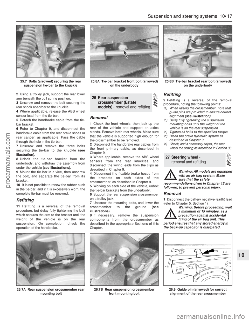
7Unscrew and remove the three bolts
securing the tie-bar to the knuckle (see
illustration).
8Unbolt the tie-bar bracket from the
underbody, and withdraw the assembly from
under the vehicle (see illustrations).
9Mount the tie-bar in a vice, then unscrew
the bolt, and separate the tie-bar from its
bracket.
10It is not possible to renew the rubber bush
in the tie-bar, and if it is excessively worn, the
complete tie-bar must be renewed.
Refitting
11Refitting is a reversal of the removal
procedure, but delay fully tightening the bolt
which secures the arm to the bracket until the
weight of the vehicle is on the rear
suspension. On completion, check the
operation of the handbrake.
Removal
1Chock the front wheels, then jack up the
rear of the vehicle and support on axles
stands. Remove both rear wheels. Make sure
that the vehicle is supported high enough for
the crossmember to be removed.
2Disconnect the handbrake rear cables from
the front primary cable, as described in
Chapter 9.
3Where applicable, remove the ABS wheel
sensors from the rear knuckles, and
disconnect the wiring leads from the clips as
described in Chapter 9.
4Disconnect the flexible brake hoses from
the brackets on both sides of the
crossmember, as described in Chapter 9.
5Working on each side of the vehicle, unbolt
the tie-bar brackets from the underbody.
6Support the rear suspension crossmember
on a trolley jack.
7Unscrew the mounting bolts, and lower the
crossmember to the ground (see
illustrations).
8If necessary, remove the suspension
components from the crossmember as
described in the appropriate Sections of this
Chapter.
Refitting
9Refitting is a reversal of the removal
procedure, noting the following points:
(a) When raising the crossmember, note that
guide pins are provided to ensure correct
alignment (see illustration).
(b) Delay fully tightening the suspension
mounting bolts until the weight of the
vehicle is on the rear suspension.
(c) Tighten all bolts to the specified torque.
(d) Bleed the brake hydraulic system as
described in Chapter 9.
(e) Check, and if necessary adjust, the rear
wheel toe setting as described in Section 36.
Warning: All models are equipped
with an air bag system. Make
sure that the safety
recommendations given in Chapter 12 are
followed, to prevent personal injury.
Removal
1Disconnect the battery negative (earth) lead
(refer to Chapter 5, Section 1).
Warning: Before proceeding, wait
a minimum of 15 minutes, as a
precaution against accidental
firing of the air bag unit. This
period ensures that any stored energy in
the back-up capacitor is dissipated.
27 Steering wheel -
removal and refitting
26 Rear suspension
crossmember (Estate
models) - removal and refitting
Suspension and steering systems 10•17
10
26.7A Rear suspension crossmember rear
mounting bolt26.7B Rear suspension crossmember
front mounting bolt26.9 Guide pin (arrowed) for correct
alignment of the rear crossmember
25.7 Bolts (arrowed) securing the rear
suspension tie-bar to the knuckle25.8A Tie-bar bracket front bolt (arrowed)
on the underbody25.8B Tie-bar bracket rear bolt (arrowed)
on the underbody
procarmanuals.com
Page 175 of 279
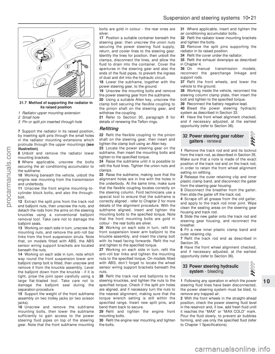
7Support the radiator in its raised position,
by inserting split pins through the small holes
in the radiator mounting extensions which
protrude through the upper mountings (see
illustration).
8Unbolt and remove the radiator lower
mounting brackets.
9Where applicable, unscrew the bolts
securing the air conditioning accumulator to
the subframe.
10Working beneath the vehicle, unbolt the
engine rear mounting from the transmission
and underbody.
11Unscrew the front engine mounting-to-
cylinder block bolts, and also the through-
bolt.
12Extract the split pins from the track rod
end balljoint nuts, then unscrew the nuts, and
detach the rods from the arms on the steering
knuckles using a conventional balljoint
removal tool. Take care not to damage the
balljoint seals.
13Working on each side in turn, unscrew the
mounting nuts, and remove the anti-roll bar
links from the front suspension struts. Note
that, on models fitted with ABS, the ABS
sensor wiring support brackets are located
beneath the nuts.
14Working on each side in turn, note which
way round the front suspension lower arm
balljoint clamp bolt is fitted, then unscrew and
remove it from the knuckle assembly. Lever
the balljoint down from the knuckle - if it is
tight, prise the joint open carefully using a
large flat-bladed tool. Take care not to
damage the balljoint seal during the
separation procedure.
15Support the weight of the front subframe
assembly on two trolley jacks (or two scissor
jacks).
16Unscrew and remove the subframe
mounting bolts, then lower the subframe
sufficiently to gain access to the power
steering fluid pipes on top of the steering
gear. Note that the front subframe mountingbolts are gold in colour - the rear ones are
silver.
17Position a suitable container beneath the
steering gear, then unscrew the union nuts
securing the power steering fluid supply,
return, and cooler lines to the steering gear.
Identify the lines for position, then unbolt the
clamps, disconnect the lines, and allow the
fluid to drain into the container. Cover the
apertures in the steering gear and also the
ends of the fluid pipes, to prevent the ingress
of dust and dirt into the hydraulic circuit.
18Lower the subframe, together with the
power steering gear, to the ground.
19Unscrew the mounting bolts and remove
the power steering gear from the subframe.
20Using a suitable Allen key, unscrew the
clamp bolt securing the flexible coupling to
the pinion shaft on the steering gear, and
withdraw the coupling.
21Refer to Section 30, paragraph 8 for
details of renewing the Teflon rings.Refitting
22Refit the flexible coupling to the pinion
shaft on the steering gear, then insert and
tighten the clamp bolt using an Allen key.
23Locate the power steering gear on the
subframe, then insert the mounting bolts and
tighten to the specified torque.
24Raise the subframe until it is possible to
refit the fluid lines. Tighten the union nuts and
clamps.
25Raise the subframe, making sure that the
alignment holes are in line with the holes in
the underbody. At the same time, make sure
that the flexible coupling locates correctly on
the steering column. Ford technicians use a
special tool to ensure that the subframe is
correctly aligned - refer to Chapter 2 for more
details of the alignment procedure. With the
subframe aligned, insert and tighten the
mounting bolts to the specified torque. Note
that the front mounting bolts are gold in
colour - the rear bolts are silver.
26Working on each side in turn, refit the
front suspension lower arm balljoint to the
knuckle assembly, and insert the clamp bolt
with its head facing forwards. Refit the nut
and tighten to the specified torque.
27Working on each side in turn, refit the
anti-roll bar links and tighten the mounting
nuts to the specified torque. On models fitted
with ABS, don’t forget to locate the wheel
sensor wiring support brackets beneath the
nuts.
28Refit the track rod end balljoints to the
steering knuckles, and tighten the nuts to the
specified torque. Check if the split pin holes
are aligned, and if necessary turn the nuts to
the nearest alignment, making sure that the
torque wrench setting is still within the
specified range. Insert new split pins, and
bend them back to secure.
29Refit and tighten the engine front
mounting bolts.
30Refit the engine rear mounting and tighten
the bolts.31Where applicable, insert and tighten the
air conditioning accumulator bolts.
32Refit the radiator lower mounting brackets
and tighten the bolts.
33Remove the split pins supporting the
radiator in its raised position.
34Refit the cover under the radiator.
35Refit the exhaust downpipe as described
in Chapter 4.
36On manual transmission models,
reconnect the gearchange linkage and
support rods.
37Refit the front wheels, and lower the
vehicle to the ground.
38Working inside the vehicle, reconnect the
steering column clamp plate, then insert the
bolt and tighten to the specified torque.
39Reconnect the battery negative lead.
40Bleed the power steering hydraulic
system as described in Section 33.
41Have the front wheel alignment checked,
and if necessary adjusted, at the earliest
opportunity (refer to Section 36).
1Remove the track rod end and its locknut
from the track rod, as described in Section 35.
Make sure that a note is made of the exact
position of the track rod end on the track rod,
in order to retain the front wheel alignment
setting on refitting.
2Release the outer retaining clip and inner
plastic clamp band, and disconnect the gaiter
from the steering gear housing.
3Disconnect the breather from the gaiter,
then slide the gaiter off the track rod.
4Scrape off all grease from the old gaiter,
and apply to the track rod inner joint. Wipe
clean the seating areas on the steering gear
housing and track rod.
5Slide the new gaiter onto the track rod and
steering gear housing, and reconnect the
breather.
6Fit a new inner plastic clamp band and
outer retaining clip.
7Refit the track rod end as described in
Section 35.
8Have the front wheel alignment checked,
and if necessary adjusted, at the earliest
opportunity (refer to Section 36).
1Following any operation in which the power
steering fluid lines have been disconnected,
the power steering system must be bled, to
remove any trapped air.
2With the front wheels in the straight-ahead
position, check the power steering fluid level
in the reservoir and, if low, add fresh fluid until
it reaches the “MAX” or “MAX COLD” mark.
Pour the fluid slowly, to prevent air bubbles
forming, and use only the specified fluid (refer
to Chapter 1 Specifications).
33 Power steering hydraulic
system - bleeding
32 Power steering gear rubber
gaiters - renewal
Suspension and steering systems 10•21
10
31.7 Method of supporting the radiator in
its raised position
1 Radiator upper mounting extension
2 Small hole
3 Pin or split pin inserted through hole
procarmanuals.com
Page 190 of 279
30Detach the mounting plate from the lock.
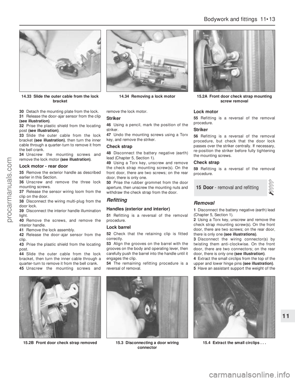
31Release the door-ajar sensor from the clip
(see illustration).
32Prise the plastic shield from the locating
post (see illustration).
33Slide the outer cable from the lock
bracket (see illustration), then turn the inner
cable through a quarter-turn to remove it from
the bell crank.
34Unscrew the mounting screws and
remove the lock motor (see illustration).
Lock motor - rear door
35Remove the exterior handle as described
earlier in this Section.
36Unscrew and remove the three lock
mounting screws.
37Release the sensor wiring loom from the
clip on the door.
38Disconnect the wiring multi-plug from the
door lock.
39Disconnect the interior handle illumination
light.
40Remove the screws, and remove the
interior handle.
41Remove the lock assembly.
42Release the door-ajar sensor from the
clip.
43Prise the plastic shield from the locating
post.
44Slide the outer cable from the lock
bracket, then turn the inner cable through a
quarter-turn to remove it from the bell crank.
45Unscrew the mounting screws andremove the lock motor.
Striker
46Using a pencil, mark the position of the
striker.
47Undo the mounting screws using a Torx
key, and remove the striker.
Check strap
48Disconnect the battery negative (earth)
lead (Chapter 5, Section 1).
49Using a Torx key, unscrew and remove
the check strap mounting screw(s). On the
front door, there are two screws; on the rear
door, there is only one.
50Prise the rubber grommet from the door
aperture, then unscrew the mounting nuts and
withdraw the check strap from the door.
Refitting
Handles (exterior and interior)
51Refitting is a reversal of the removal
procedure.
Lock barrel
52Check that the retaining clip is fitted
correctly.
53Align the grooves on the barrel with the
grooves on the body and operating lever, then
carefully push the barrel into the handle until it
engages the clip.
54The remaining refitting procedure is a
reversal of removal.
Lock motor
55Refitting is a reversal of the removal
procedure.
Striker
56Refitting is a reversal of the removal
procedure, but check that the door lock
passes over the striker centrally. If necessary,
re-position the striker before fully tightening
the mounting screws.
Check strap
59Refitting is a reversal of the removal
procedure.
Removal
1Disconnect the battery negative (earth) lead
(Chapter 5, Section 1).
2Using a Torx key, unscrew and remove the
check strap mounting screw(s). On the front
door, there are two screws; on the rear door,
there is only one (see illustrations).
3Disconnect the wiring connector(s) by
twisting them anti-clockwise. On the front
door, there are two connectors; on the rear
door, there is only one (see illustration).
4Extract the small circlips from the top of the
upper and lower hinge pins (see illustration).
5Have an assistant support the weight of the
15 Door - removal and refitting
Bodywork and fittings 11•13
11
15.2B Front door check strap removed15.3 Disconnecting a door wiring
connector15.4 Extract the small circlips . . .
14.33 Slide the outer cable from the lock
bracket14.34 Removing a lock motor15.2A Front door check strap mounting
screw removal
procarmanuals.com
Page 264 of 279
Buying spare parts
Spare parts are available from many
sources; for example, Ford garages, other
garages and accessory shops, and motor
factors. Our advice regarding spare part
sources is as follows.
Officially-appointed Ford garages- This is
the best source for parts which are peculiar to
your vehicle, and which are not generally
available (eg complete cylinder heads, internal
transmission components, badges, interior
trim etc). It is also the only place at which you
should buy parts if the vehicle is still under
warranty. To be sure of obtaining the correct
parts, it will be necessary to give the storeman
the full Vehicle Identification Number, and if
possible, to take the old parts along for
positive identification. Many parts are
available under a factory exchange scheme -
any parts returned should always be clean. It
obviously makes good sense to go straight to
the specialists on your vehicle for this type of
part, as they are best equipped to supply you.
Other garages and accessory shops- These
are often very good places to buy materials
and components needed for the maintenance
of your vehicle (eg oil filters, spark plugs,
bulbs, drivebelts, oils and greases, touch-up
paint, filler paste, etc). They also sell general
accessories, usually have convenient opening
hours, charge lower prices, and can often be
found not far from home.
Motor factors- Good factors will stock all
the more important components which wear
out comparatively quickly (eg exhaust
systems, brake pads, seals and hydraulic
parts, clutch components, bearing shells,
pistons, valves etc). Motor factors will often
provide new or reconditioned components on
a part-exchange basis - this can save a
considerable amount of money.
Vehicle identification numbers
Modifications are a continuing and
unpublicised process in vehicle manufacture,
quite apart from major model changes. Spare
parts manuals and lists are compiled upon a
numerical basis, the appropriate identification
number or code being essential to correct
identification of the component concerned.
When ordering spare parts, always give asmuch information as possible. Quote the
vehicle model, year of manufacture, Vehicle
Identification Number and engine numbers, as
appropriate.
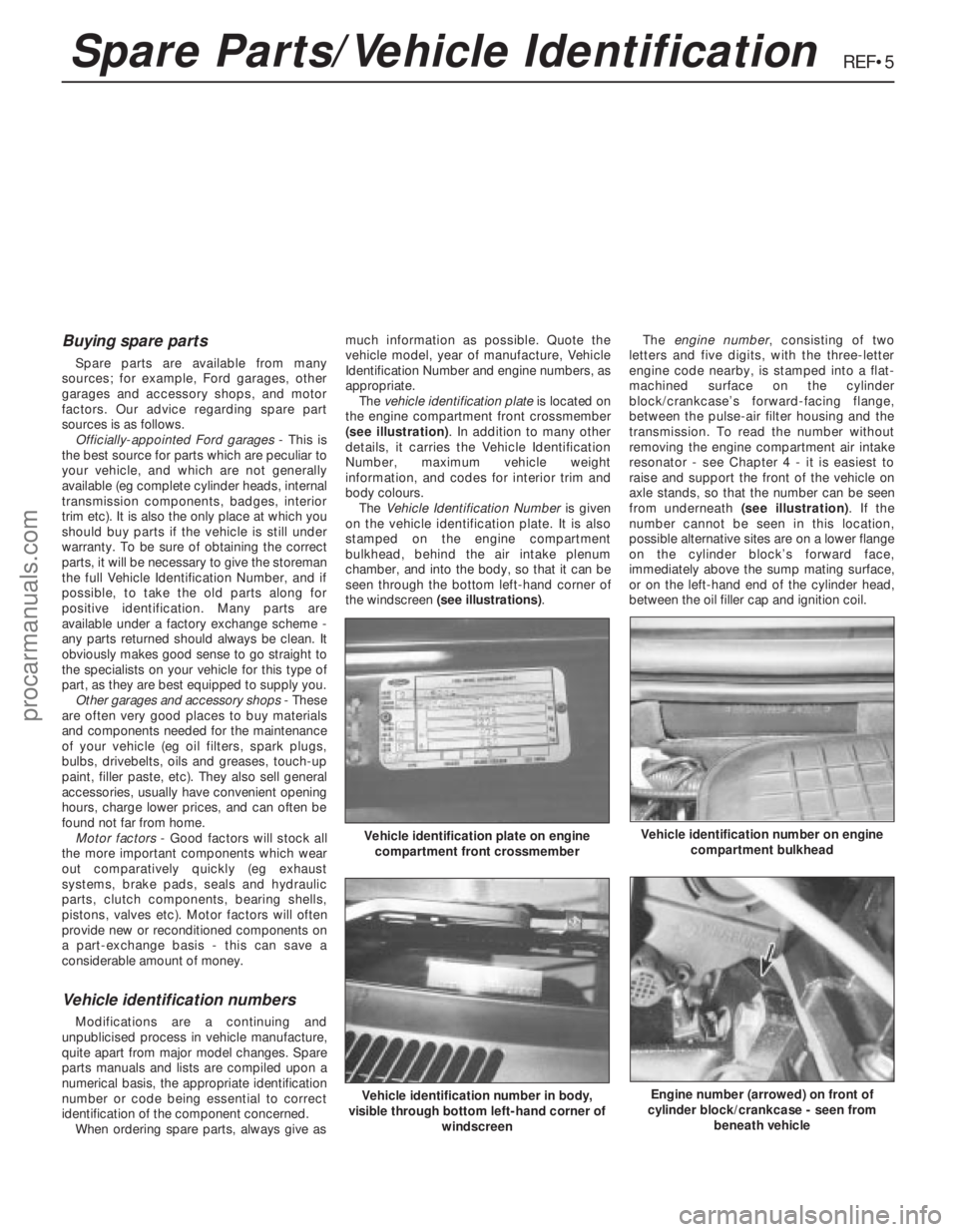
The vehicle identification plateis located on
the engine compartment front crossmember
(see illustration). In addition to many other
details, it carries the Vehicle Identification
Number, maximum vehicle weight
information, and codes for interior trim and
body colours.
The Vehicle Identification Numberis given
on the vehicle identification plate. It is also
stamped on the engine compartment
bulkhead, behind the air intake plenum
chamber, and into the body, so that it can be
seen through the bottom left-hand corner of
the windscreen (see illustrations).The engine number, consisting of two
letters and five digits, with the three-letter
engine code nearby, is stamped into a flat-
machined surface on the cylinder
block/crankcase’s forward-facing flange,
between the pulse-air filter housing and the
transmission. To read the number without
removing the engine compartment air intake
resonator - see Chapter 4 - it is easiest to
raise and support the front of the vehicle on
axle stands, so that the number can be seen
from underneath (see illustration). If the
number cannot be seen in this location,
possible alternative sites are on a lower flange
on the cylinder block’s forward face,
immediately above the sump mating surface,
or on the left-hand end of the cylinder head,
between the oil filler cap and ignition coil.
REF•5
Vehicle identification plate on engine
compartment front crossmember
Vehicle identification number in body,
visible through bottom left-hand corner of
windscreen
Vehicle identification number on engine
compartment bulkhead
Engine number (arrowed) on front of
cylinder block/crankcase - seen from
beneath vehicle
Spare Parts/Vehicle Identification
procarmanuals.com