1993 CHEVROLET PLYMOUTH ACCLAIM AA body
[x] Cancel search: AA bodyPage 2398 of 2438
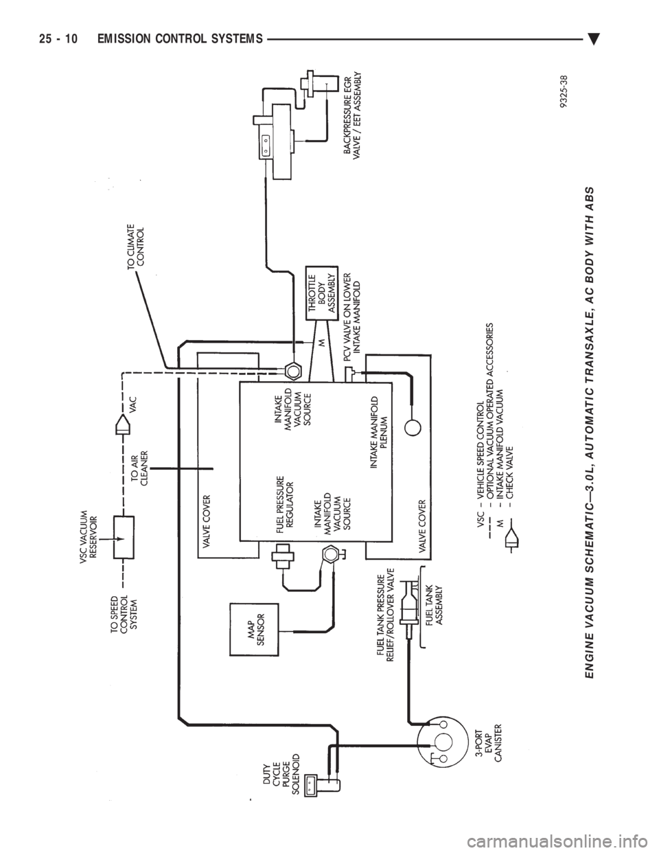
ENGINE VACUUM SCHEMATICÐ3.0L, AUTOMATIC TRANSAXLE, AC BODY WITH ABS
25 - 10 EMISSION CONTROL SYSTEMS Ä
Page 2401 of 2438
EVAPORATION CONTROL SYSTEM
The evaporation control system prevents the emis-
sion of fuel tank vapors into the atmosphere. When fuel
evaporates in the fuel tank, the vapors pass through
vent hoses or tubes to a charcoal canister. The canister
temporarily holds the vapors. The powertrain control
module (PCM) allows intake manifold vacuum to draw
vapors into the combustion chambers during certain
operating conditions. The PCM uses the canister purge
solenoid to regulate vapor flow. On 2.2L and 2.5L TBI, 3.3L, and 3.8L engines,
manifold vacuum purges the vapors at idle as well as
off idle. These engines use a bi-level purge system. The
system uses 2 sources of vacuum remove fuel vapors
from the canister. Turbo III engines use a tri-level canister purge sys-
tem. In this system, fuel vapors are drawn into the
engine through the throttle body and air cleaner. Fuel
vapors are drawn in at closed throttle, part throttle,
and wide open throttle (in boost). The 2.5L MPI (flexible fuel AA-Body) and 3.0L have
a duty cycle purge system. The powertrain control
module PCM controls vapor flow by operating the duty
cycle EVAP purge solenoid. Refer to Duty Cycle EVAP
Purge Solenoid in this section. The evaporative system uses specially manu-
factured hoses. If they need replacement, only
use fuel resistant hose.
PRESSURE RELIEF/ROLLOVER VALVE
All vehicles have a combination pressure relief and
rollover valve. The dual function valve relieves fuel
tank pressure. The valve also prevents fuel flow
through the fuel tank vent valve hoses if the vehicle
accidentally rolls over. All vehicles pass a 360É rollover. The pressure relief valve opens at a certain pressure.
When fuel tank pressure increases above the cali-
brated pressure, the valve opens to release fuel tank
vapors pressure. The evaporative (charcoal) canister
stores the vapors. For pressure relief/rollover valve
service, refer to the Fuel Tank section of Group 14.
EVAPORATIVE CANISTER
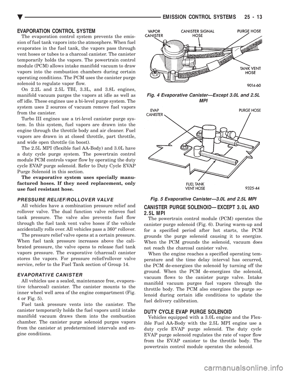
All vehicles use a sealed, maintenance free, evapora-
tive (charcoal) canister. The canister mounts to the
inner wheel well area of the engine compartment (Fig.
4 or Fig. 5). Fuel tank pressure vents into the canister. The
canister temporarily holds the fuel vapors until intake
manifold vacuum draws them into the combustion
chamber. The canister purge solenoid purges vapors
from the canister at predetermined intervals and en-
gine conditions.
CANISTER PURGE SOLENOIDÐEXCEPT 3.0L AND
2.5L MPI
The powertrain control module (PCM) operates the
canister purge solenoid (Fig. 6). During warm-up and
for a specified period after hot starts, the PCM
grounds the purge solenoid causing it to energize.
When the PCM grounds the solenoid, vacuum does
not reach the charcoal canister valve. When the engine reaches a specified operating tem-
perature and the time delay interval has occurred,
the PCM de-energizes the solenoid by turning off the
ground. When the PCM de-energizes the solenoid,
vacuum flows to the canister purge valve. Intake
manifold vacuum purges fuel vapors through the
throttle body. The PCM also energizes the purge so-
lenoid during certain idle conditions to update the
fuel delivery calibration.
DUTY CYCLE EVAP PURGE SOLENOID
Vehicles equipped with a 3.0L engine and the Flex-
ible Fuel AA-Body with the 2.5L MPI engine use a
duty cycle EVAP purge solenoid. The duty cycle
EVAP purge solenoid regulates the rate of vapor flow
from the EVAP canister to the throttle body. The
powertrain control module operates the solenoid.
Fig. 4 Evaporative CanisterÐExcept 3.0L and 2.5L MPI
Fig. 5 Evaporative CanisterÐ3.0L and 2.5L MPI
Ä EMISSION CONTROL SYSTEMS 25 - 13
Page 2402 of 2438
During the cold start warm-up period and the hot
start time delay, the PCM does not energize the so-
lenoid. When de-energized, no vapors are purged.
The PCM de-energizes the solenoid during open loop
operation. The engine enters closed loop operation after it
reaches a specified temperature and the time delay
ends. During closed loop operation, the PCM ener-
gizes and de-energizes the solenoid approximately 5
to 10 times per second, depending upon operating
conditions. The PCM varies the vapor flow rate by
changing solenoid pulse width. Pulse width is the
amount of time the solenoid energizes. The PCM ad-
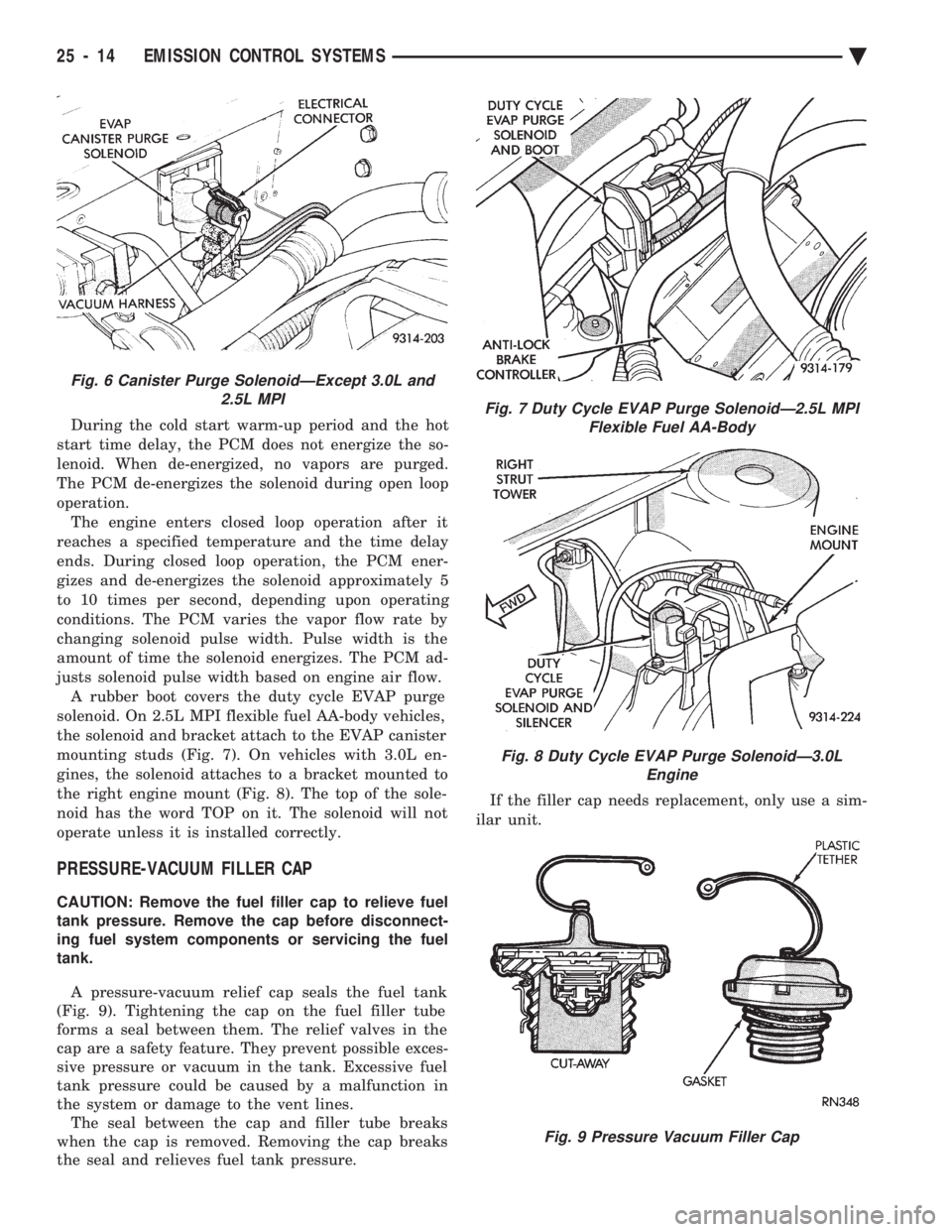
justs solenoid pulse width based on engine air flow. A rubber boot covers the duty cycle EVAP purge
solenoid. On 2.5L MPI flexible fuel AA-body vehicles,
the solenoid and bracket attach to the EVAP canister
mounting studs (Fig. 7). On vehicles with 3.0L en-
gines, the solenoid attaches to a bracket mounted to
the right engine mount (Fig. 8). The top of the sole-
noid has the word TOP on it. The solenoid will not
operate unless it is installed correctly.
PRESSURE-VACUUM FILLER CAP
CAUTION: Remove the fuel filler cap to relieve fuel
tank pressure. Remove the cap before disconnect-
ing fuel system components or servicing the fuel
tank.
A pressure-vacuum relief cap seals the fuel tank
(Fig. 9). Tightening the cap on the fuel filler tube
forms a seal between them. The relief valves in the
cap are a safety feature. They prevent possible exces-
sive pressure or vacuum in the tank. Excessive fuel
tank pressure could be caused by a malfunction in
the system or damage to the vent lines. The seal between the cap and filler tube breaks
when the cap is removed. Removing the cap breaks
the seal and relieves fuel tank pressure. If the filler cap needs replacement, only use a sim-
ilar unit.
Fig. 6 Canister Purge SolenoidÐExcept 3.0L and 2.5L MPI
Fig. 7 Duty Cycle EVAP Purge SolenoidÐ2.5L MPIFlexible Fuel AA-Body
Fig. 8 Duty Cycle EVAP Purge SolenoidÐ3.0L Engine
Fig. 9 Pressure Vacuum Filler Cap
25 - 14 EMISSION CONTROL SYSTEMS Ä
Page 2404 of 2438
CRANKCASE VENT FILTER
All engines have a crankcase vent filter. The filter
cleans outside air before it enters the PCV system.
On 2.5L engines, the filter mounts to the upper shell
assembly of the air cleaner. On 2.5L MPI (Flexible
Fuel AA-body) and Turbo III engines, the filter at-
taches to the inside of the filter element box, next to
the filter element. On 3.0L engines, it attaches to the
inside of the filter element box under the filter ele- ment. On the 3.3L engines, the filter mounts to the
bottom of the filter element box. Refer to Group 0 for
mileage intervals and service procedures.
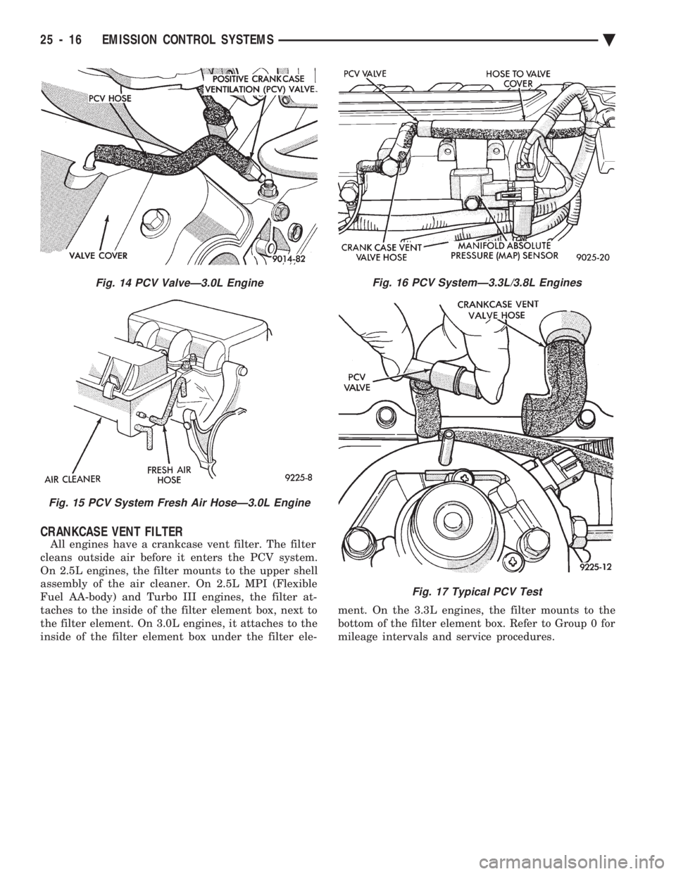
Fig. 14 PCV ValveÐ3.0L Engine
Fig. 15 PCV System Fresh Air HoseÐ3.0L Engine
Fig. 16 PCV SystemÐ3.3L/3.8L Engines
Fig. 17 Typical PCV Test
25 - 16 EMISSION CONTROL SYSTEMS Ä
Page 2405 of 2438
EXHAUST EMISSION CONTROLS INDEX
page page
Air Aspiration System ..................... 24
EGR Gas Flow Test ...................... 21
EGR System On-Board Diagnostics ........... 21
EGR Tube ServiceÐ2.2L and 2.5L TBI Engines . 22
EGR Tube ServiceÐ3.0L Engines ............ 22
EGR Tube ServiceÐ3.3L and 3.8L Engines .... 22
EGR Valve ServiceÐ2.2L and 2.5L TBI Engines . 22 EGR Valve ServiceÐ3.0L Engines
........... 22
EGR Valve ServiceÐ3.3L and 3.8L Engines .... 22
Exhaust Gas Recirculation (EGR) System ...... 20
Exhaust Gas Recirculation (EGR) System Test . . 21
Heated Inlet Air System ................... 17
Heated Oxygen Sensor (O
2Sensor) .......... 18
HEATED INLET AIR SYSTEM
2.5L MPI (Flexible Fuel AA-body), Turbo III, 3.0L,
3.3L and 3.8L engines do not use a heated inlet air
system. 2.2L and 2.5L TBI air cleaners have a heated air
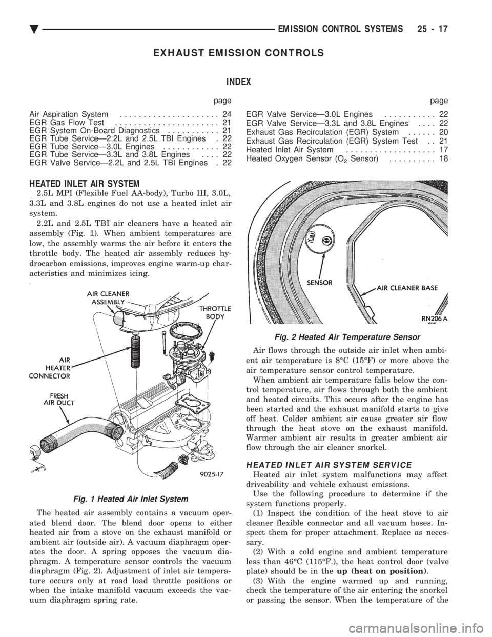
assembly (Fig. 1). When ambient temperatures are
low, the assembly warms the air before it enters the
throttle body. The heated air assembly reduces hy-
drocarbon emissions, improves engine warm-up char-
acteristics and minimizes icing.
The heated air assembly contains a vacuum oper-
ated blend door. The blend door opens to either
heated air from a stove on the exhaust manifold or
ambient air (outside air). A vacuum diaphragm oper-
ates the door. A spring opposes the vacuum dia-
phragm. A temperature sensor controls the vacuum
diaphragm (Fig. 2). Adjustment of inlet air tempera-
ture occurs only at road load throttle positions or
when the intake manifold vacuum exceeds the vac-
uum diaphragm spring rate. Air flows through the outside air inlet when ambi-
ent air temperature is 8ÉC (15ÉF) or more above the
air temperature sensor control temperature. When ambient air temperature falls below the con-
trol temperature, air flows through both the ambient
and heated circuits. This occurs after the engine has
been started and the exhaust manifold starts to give
off heat. Colder ambient air cause greater air flow
through the heat stove on the exhaust manifold.
Warmer ambient air results in greater ambient air
flow through the air cleaner snorkel.
HEATED INLET AIR SYSTEM SERVICE
Heated air inlet system malfunctions may affect
driveability and vehicle exhaust emissions. Use the following procedure to determine if the
system functions properly. (1) Inspect the condition of the heat stove to air
cleaner flexible connector and all vacuum hoses. In-
spect them for proper attachment. Replace as neces-
sary. (2) With a cold engine and ambient temperature
less than 46ÉC (115ÉF.), the heat control door (valve
plate) should be in the up (heat on position).
(3) With the engine warmed up and running,
check the temperature of the air entering the snorkel
or passing the sensor. When the temperature of the
Fig. 1 Heated Air Inlet System
Fig. 2 Heated Air Temperature Sensor
Ä EMISSION CONTROL SYSTEMS 25 - 17
Page 2407 of 2438
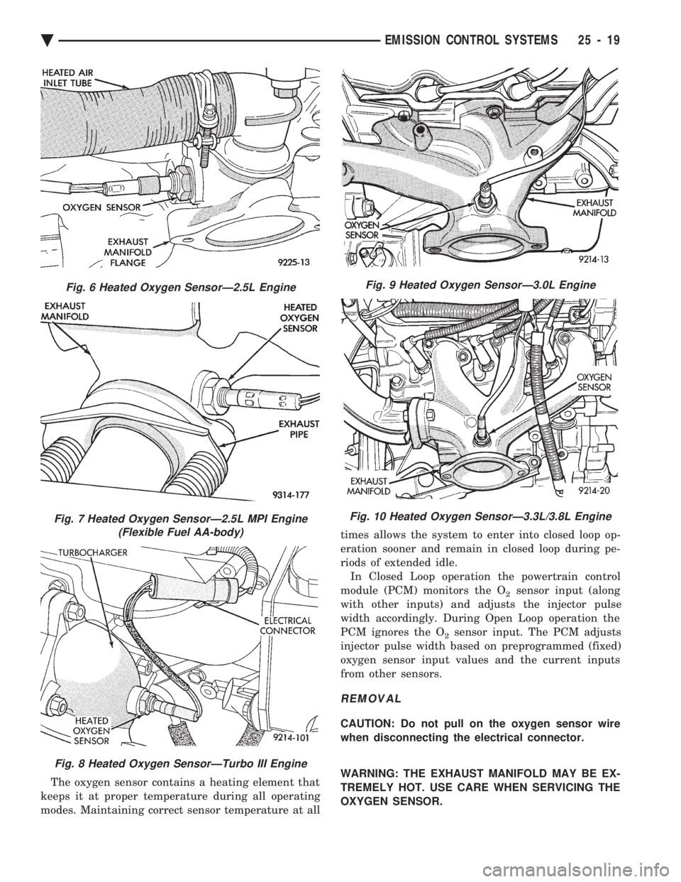
The oxygen sensor contains a heating element that
keeps it at proper temperature during all operating
modes. Maintaining correct sensor temperature at all times allows the system to enter into closed loop op-
eration sooner and remain in closed loop during pe-
riods of extended idle.
In Closed Loop operation the powertrain control
module (PCM) monitors the O
2sensor input (along
with other inputs) and adjusts the injector pulse
width accordingly. During Open Loop operation the
PCM ignores the O
2sensor input. The PCM adjusts
injector pulse width based on preprogrammed (fixed)
oxygen sensor input values and the current inputs
from other sensors.
REMOVAL
CAUTION: Do not pull on the oxygen sensor wire
when disconnecting the electrical connector.
WARNING: THE EXHAUST MANIFOLD MAY BE EX-
TREMELY HOT. USE CARE WHEN SERVICING THE
OXYGEN SENSOR.
Fig. 6 Heated Oxygen SensorÐ2.5L Engine
Fig. 7 Heated Oxygen SensorÐ2.5L MPI Engine (Flexible Fuel AA-body)
Fig. 8 Heated Oxygen SensorÐTurbo III Engine
Fig. 9 Heated Oxygen SensorÐ3.0L Engine
Fig. 10 Heated Oxygen SensorÐ3.3L/3.8L Engine
Ä EMISSION CONTROL SYSTEMS 25 - 19
Page 2408 of 2438
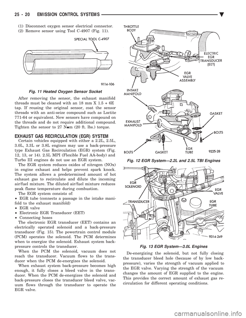
(1) Disconnect oxygen sensor electrical connector.
(2) Remove sensor using Tool C-4907 (Fig. 11).
After removing the sensor, the exhaust manifold
threads must be cleaned with an 18 mm X 1.5 + 6E
tap. If reusing the original sensor, coat the sensor
threads with an anti-seize compound such as Loctite
771-64 or equivalent. New sensors have compound on
the threads and do not require additional compound.
Tighten the sensor to 27 N Im (20 ft. lbs.) torque.
EXHAUST GAS RECIRCULATION (EGR) SYSTEM
Certain vehicles equipped with either a 2.2L, 2.5L,
3.0L, 3.3L or 3.8L engines may use a back-pressure
type Exhaust Gas Recirculation (EGR) system (Fig.
12, 13, or 14). 2.5L MPI (Flexible Fuel AA-body) and
Turbo III engines do not use an EGR system. The EGR system reduces oxides of nitrogen (NOx)
in engine exhaust and helps prevent spark knock.
The system allows a predetermined amount of hot
exhaust gas to recirculate and dilute the incoming
air/fuel mixture. The diluted air/fuel mixture reduces
peak flame temperature during combustion. The EGR system consists of:
² EGR tube (connects a passage in the intake mani-
fold to the exhaust manifold)
² EGR valve
² Electronic EGR Transducer (EET)
² Connecting hoses
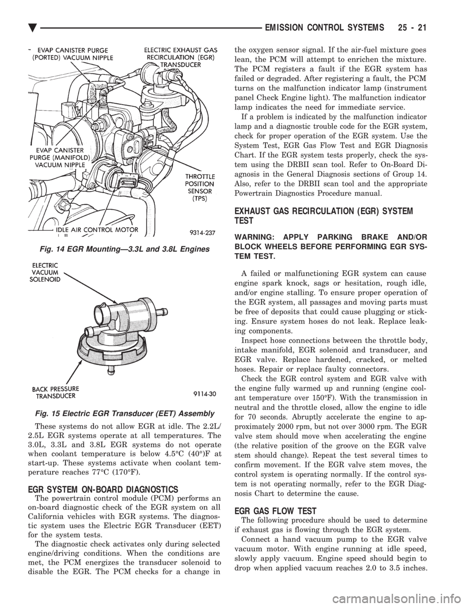
The electronic EGR transducer (EET) contains an
electrically operated solenoid and a back-pressure
transducer (Fig. 15). The powertrain control module
(PCM) operates the solenoid. The PCM determines
when to energize the solenoid. Exhaust system back-
pressure controls the transducer. When the PCM the solenoid, vacuum does not
reach the transducer. Vacuum flows to the trans-
ducer when the PCM de-energizes the solenoid. When exhaust system back-pressure becomes high
enough, it fully closes a bleed valve in the trans-
ducer. When the PCM de-energizes the solenoid and
back-pressure closes the transducer bleed valve, vac-
uum flows through the transducer to operate the
EGR valve. De-energizing the solenoid, but not fully closing
the transducer bleed hole (because of by low back-
pressure), varies the strength of vacuum applied to
the EGR valve. Varying the strength of the vacuum
changes the amount of EGR supplied to the engine.
This provides the correct amount of exhaust gas re-
circulation for different operating conditions.
Fig. 11 Heated Oxygen Sensor Socket
Fig. 12 EGR SystemÐ2.2L and 2.5L TBI Engines
Fig. 13 EGR SystemÐ3.0L Engines
25 - 20 EMISSION CONTROL SYSTEMS Ä
Page 2409 of 2438
These systems do not allow EGR at idle. The 2.2L/
2.5L EGR systems operate at all temperatures. The
3.0L, 3.3L and 3.8L EGR systems do not operate
when coolant temperature is below 4.5ÉC (40É)F at
start-up. These systems activate when coolant tem-
perature reaches 77ÉC (170ÉF).
EGR SYSTEM ON-BOARD DIAGNOSTICS
The powertrain control module (PCM) performs an
on-board diagnostic check of the EGR system on all
California vehicles with EGR systems. The diagnos-
tic system uses the Electric EGR Transducer (EET)
for the system tests. The diagnostic check activates only during selected
engine/driving conditions. When the conditions are
met, the PCM energizes the transducer solenoid to
disable the EGR. The PCM checks for a change in the oxygen sensor signal. If the air-fuel mixture goes
lean, the PCM will attempt to enrichen the mixture.
The PCM registers a fault if the EGR system has
failed or degraded. After registering a fault, the PCM
turns on the malfunction indicator lamp (instrument
panel Check Engine light). The malfunction indicator
lamp indicates the need for immediate service.
If a problem is indicated by the malfunction indicator
lamp and a diagnostic trouble code for the EGR system,
check for proper operation of the EGR system. Use the
System Test, EGR Gas Flow Test and EGR Diagnosis
Chart. If the EGR system tests properly, check the sys-
tem using the DRBII scan tool. Refer to On-Board Di-
agnosis in the General Diagnosis sections of Group 14.
Also, refer to the DRBII scan tool and the appropriate
Powertrain Diagnostics Procedure manual.
EXHAUST GAS RECIRCULATION (EGR) SYSTEM
TEST
WARNING: APPLY PARKING BRAKE AND/OR
BLOCK WHEELS BEFORE PERFORMING EGR SYS-
TEM TEST.
A failed or malfunctioning EGR system can cause
engine spark knock, sags or hesitation, rough idle,
and/or engine stalling. To ensure proper operation of
the EGR system, all passages and moving parts must
be free of deposits that could cause plugging or stick-
ing. Ensure system hoses do not leak. Replace leak-
ing components. Inspect hose connections between the throttle body,
intake manifold, EGR solenoid and transducer, and
EGR valve. Replace hardened, cracked, or melted
hoses. Repair or replace faulty connectors.
Check the EGR control system and EGR valve with
the engine fully warmed up and running (engine cool-
ant temperature over 150ÉF). With the transmission in
neutral and the throttle closed, allow the engine to idle
for 70 seconds. Abruptly accelerate the engine to ap-
proximately 2000 rpm, but not over 3000 rpm. The EGR
valve stem should move when accelerating the engine
(the relative position of the groove on the EGR valve
stem should change). Repeat the test several times to
confirm movement. If the EGR valve stem moves, the
control system is operating normally. If the control sys-
tem is not operating normally, refer to the EGR Diag-
nosis Chart to determine the cause.
EGR GAS FLOW TEST
The following procedure should be used to determine
if exhaust gas is flowing through the EGR system.
Connect a hand vacuum pump to the EGR valve
vacuum motor. With engine running at idle speed,
slowly apply vacuum. Engine speed should begin to
drop when applied vacuum reaches 2.0 to 3.5 inches.
Fig. 14 EGR MountingÐ3.3L and 3.8L Engines
Fig. 15 Electric EGR Transducer (EET) Assembly
Ä EMISSION CONTROL SYSTEMS 25 - 21